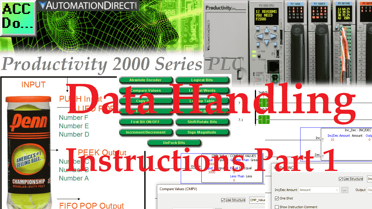
Data handling instructions are used to perform movement and manipulations of the memory in the programmable logic controller. The Productivity 2000 Series PLC has fifteen different data handling instructions that can be used in various applications.
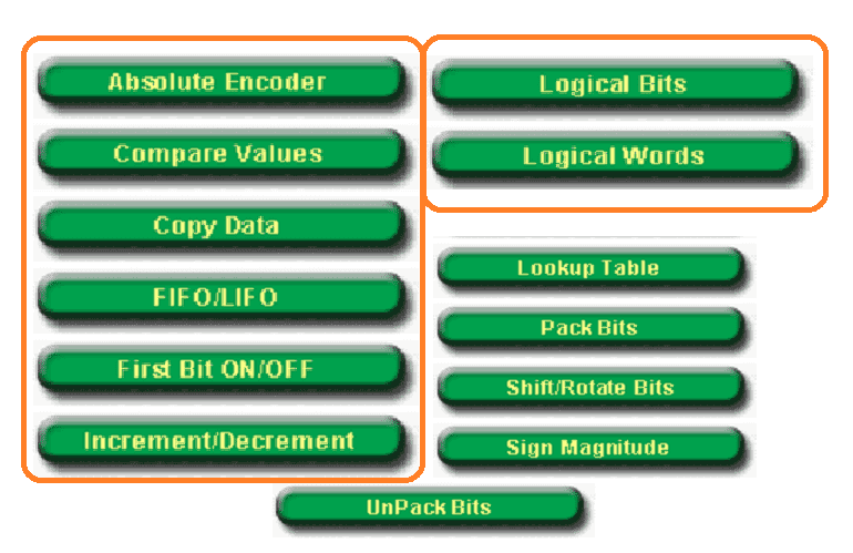 It is important to look at the capabilities of your programmable logic controller. This will lead you to different applications so that you can apply this knowledge. In the data handling instructions first part, we will be looking at the following instructions:
Absolute Encoder (ABSE) – Encoder input using Gray Code or Binary Code
Compare Values (CMPV) – Compare two different tags and determine if they are equal, greater than, or less than.
Copy Data (CPD) – Copy tags from one location and place them in another.
FIFO / LIFO (FILI) – First in, first out / Last in, first out
First Bit On/Off (FIB) – Determines first Bit on in a series of bit tags.
Inc / Dec (INC) – Increment or decrement a tag by a number.
Logical Bits (LOG) – Perform logical operations on Boolean input tags.
Logical Words (LOGW) – Perform logical operations on tags.
In part 2 of data handling, we will continue with additional data handling instructions.
Let’s get started with the Productivity 2000 Series PLC data handling instructions.
Previously in this Productivity 2000 series PLC, we have discussed the following:
P2000 Hardware Features – Video
Productivity Suite Software Install – Video
Communication (System Configuration) – Video
First Program – Video
Debug Mode – Video
PLC Program Documentation – Video
PLC CPU Display – Video
PLC Online Programming – Video
PLC Tag Database – Video
Ladder Logic Contacts – Video
Ladder Logic Outputs – Video
Timers – Video
Counter – Video
Productivity 2000 PLC Ladder Logic Math – Video
Absolute Encoder (ABSE) – Productivity 2000 Data Handling
This instruction will decode Bit Patterns (maximum 12 bits) from Gray Code or Binary Absolute Encoder. An encoder is usually attached to a moving device. As the encoder turns, the corresponding position can be read in the PLC.
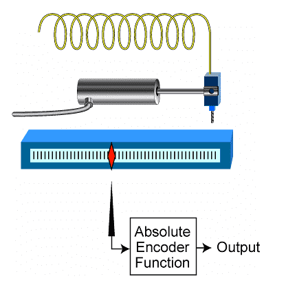 Grey code is often used for positioning because only one-bit changes at a time. If power is lost and then returned, the position is easily read. If multiple bits change position, it would be challenging to read the exact location when using binary.
Here’s a Quick Way to Convert Grey Code into Binary for PLC – This post will show you the logic behind this instruction.
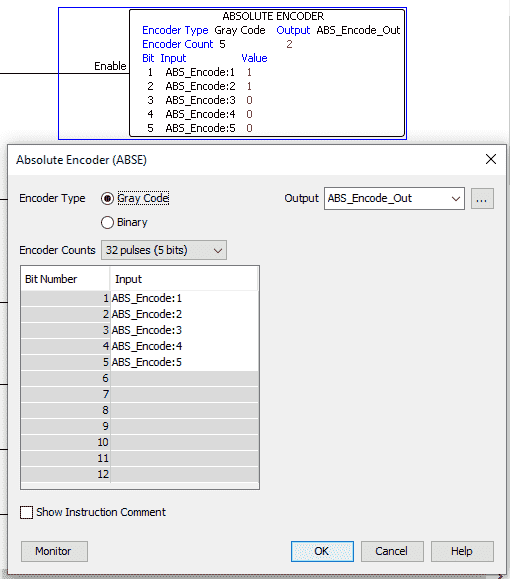 We have selected Gray Code 5 bit. This will give us 32 pulses per revolution. Inputs will be ABS_Encode:1 to 5. The output tag will be called ABS_Encode_Out.
Note that the colon means the Bit of the tag.
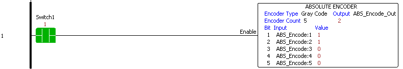 When Switch1 is turned on, the instruction will encode the 5 bits of tag ABS_Encode and output to tag ABS_Encode_Out.
Here is a chart of the 5-bit Gray Code.
| Decimal | Binary | Grey Code |
| 0 | 00000 | 00000 |
| 1 | 00001 | 00001 |
| 2 | 00010 | 00011 |
| 3 | 00011 | 00010 |
| 4 | 00100 | 00110 |
| 5 | 00101 | 00111 |
| 6 | 00110 | 00101 |
| 7 | 00111 | 00100 |
| 8 | 01000 | 01100 |
| 9 | 01001 | 01101 |
| 10 | 01010 | 01111 |
| 11 | 01011 | 01110 |
| 12 | 01100 | 01010 |
| 13 | 01101 | 01011 |
| 14 | 01110 | 01001 |
| 15 | 01111 | 01000 |
| 16 | 10000 | 11000 |
| 17 | 10001 | 11001 |
| 18 | 10010 | 11011 |
| 19 | 10011 | 11010 |
| 20 | 10100 | 11110 |
| 21 | 10101 | 11111 |
| 22 | 10110 | 11101 |
| 23 | 10111 | 11100 |
| 24 | 11000 | 10100 |
| 25 | 11001 | 10101 |
| 26 | 11010 | 10111 |
| 27 | 11011 | 10110 |
| 28 | 11100 | 10010 |
| 29 | 11101 | 10011 |
| 30 | 11110 | 10001 |
| 31 | 11111 | 10000 |
Compare Values (CMPV) – Productivity 2000 Data Handling
This instruction will set greater, less, and equal bit flags based on comparing two tags.
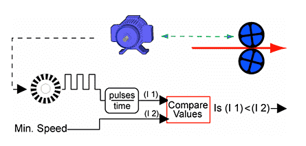 An example would be comparing a motor’s speed to a minimum rate. This will determine in the logic what should be done.
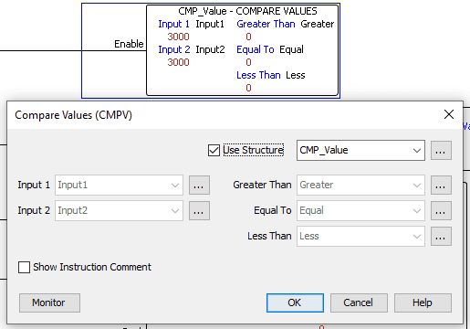 We are using the structure name of CMP_Value. This will automatically set the tags for Input 1 and 2 and the three Boolean flags.
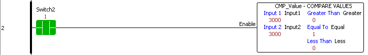 When Switch2 is on, input one is compared to input 2. In our example, they are equal, so the equal bit flag is on. Watch the video below to see this instruction operate.
Copy Data (CPD) – Productivity 2000 Data Handling
This instruction will copy the data or binary pattern from the specified source tags to the corresponding destination tags.
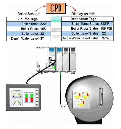 Moving data from one location to another is a common task. We are moving four memory register items to another location in this example. This will then be displayed on an HMI. (Human Machine Interface)
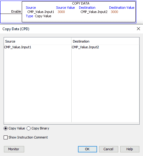 We will copy the value of the CMP_Value.Input1 tag to CMP_Value.Input2 tag. You can copy 16 tags from one location to another with this instruction.
 When Switch3 is on, the value is copied from the source to the destination for every scan.
FIFO / LIFO (FILI) – First in first out / Last in first out – Productivity Data Handling
This instruction will allow data to be added (pushed), removed (pulled, popped), or viewed (peek) from a block of memory (buffer).
 The above is an analogy of the FIFO / LIFO instruction. The tennis ball sleeve represents the memory block, and each ball represents one number. Our ball sleeve can have any number of balls in it at a given time and will expand or contract to suit our needs.
When we add a ball to the sleeve, this is a push.
When we remove a ball from the top of the sleeve, this is a LIFO (Last in, first out.) pull.
Removing a ball from the bottom of the sleeve would be a FIFO (First in, first out.) pull.
We can look at the balls in the sleeve at any time. This would be a PEEK.
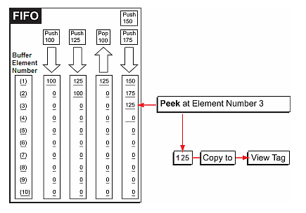 Here is another picture showing how the FIFO instruction works. Time is along the x-axis as we push or pop information into the memory block.
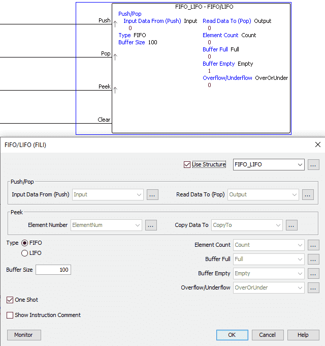 A structure called FIFO_LIFO is used to set up the tags. The type will be FIFO (first in, first out). We will set the one shot on the inputs so the inputs will only trigger from an off-to-on state for one scan of the PLC.
How to make a one-shot in the PLC
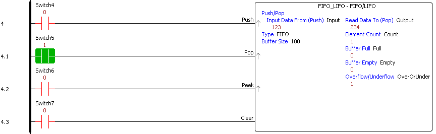 Switch4 is our one-shot push input. It will move the input data to the memory buffer when this is on.
Switch5 is our one-shot pop input. This will remove information from our memory buffer and place it in the output. Since we are using a FIFO, the first input will be the first output in the buffer.
Switch6 is the one-shot peek input. The element number of the memory buffer will be copied to the CopyTo tag.
Switch 7 is a clear instruction. This will clear the buffer and turn on the empty buffer Bit.
First Bit On/Off (FIB) – Productivity 2000 Data Handling
This instruction determines the first Bit in a series of bit tags.
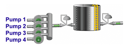 An example of this instruction would be to monitor pumps for errors. If an error occurs, this instruction will indicate which pump failed so we can use logic to shut the others down.
 A structure named First_Bit is used. This will set up Bit1 to Bit8 for the inputs to monitor. The first Bit detected and the first-bit number will be set as the outputs when the instruction input rung is on.
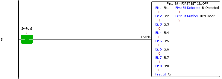 When Switch5 is turned on, the inputs are scanned, and the outputs are set when the first Bit is detected.
Inc / Dec (INC) – Productivity 2000 Data Handling
This instruction will increment or decrement a tag by a specific number.
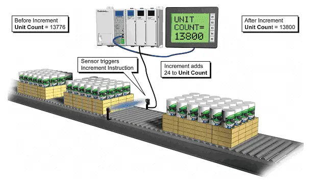 In this example, we are using the increment instruction to add 24 items to the total if the sensor detects a box.
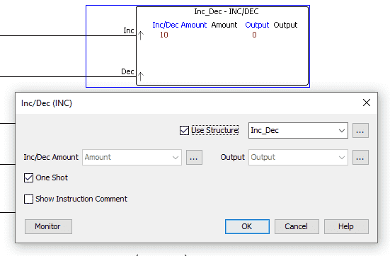 We are using Inc_Dec as the structure name. Select the One-Shot for the input so our increment and decrement will happen only on a transition from off to on. When you define the tags (Tag Database), you can make the tags’ memory retentive. This means their value will be retained through a power failure or switching the PLC from program to run mode.
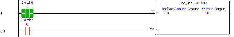 When Switch6 is on, the output is incremented by 10. Switch 7 will decrement the output by ten each time.
Logical Bits (LOG) – Productivity 2000 Data Handling
This instruction will perform logical operations on the boolean input tags.
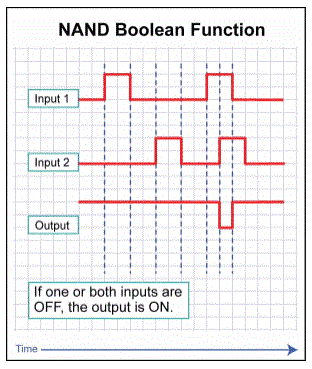 Basic gate functions can be done with the inputs to this instruction. In this example, a NAND gate is demonstrated.
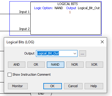 We will set the output to the Logical_Bit_Out flag. This will be the result of our NAND expression that we will also set.
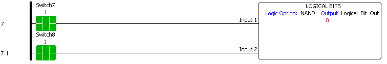 Our logical NAND operation will be performed with Switch7 (Input 1) and Switch8 (Input 2).
Note: Multiple Boolean conditions could be entered for each rung input.
Logical Words (LOGW) – Productivity 2000 Data Handling
This instruction will perform logical operations on tags.
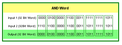 In this example, we will use the ‘AND’ of the two input registers. If both bits in the word are on, then the corresponding output bit will be on.
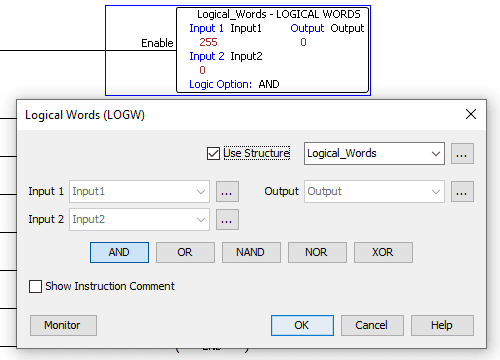 We will use Logical_Words as the structure name for the instruction. Our logical operation will be AND.
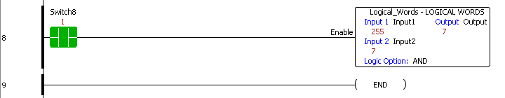 When Switch8 is on, we will look at input one and perform a logical AND with input 2. Since input 2 has the value of 255. (0000 0000 1111 1111) only the last 8 bits of input 1 will be transferred to the output. We have masked the other bits from the input 1 number.
Download the P2000 PLC program here.
Watch the video below for the data handling instructions used in our Productivity 2000 Series PLC.
Productivity 2000 Series PLC from Automation Direct
Overview Link (Additional Information on the Unit)
Configuration (Configure and purchase a system – BOM)
User Manual and Inserts (Installation and Setup Guides)
Productivity Suite Overview (Features of the fully functional free software package for the Productivity Family of PLC (PAC) controllers)
Productivity Suite Programming Software (Free Download Link)
This software contains all the instructions and helps files for the Productivity Series.
Watch on YouTube: Productivity 2000 PLC Data Handling Part 1
If you have any questions or need further information, please contact me.
Thank you,
Garry
If you’re like most of my readers, you’re committed to learning about technology. Numbering systems used in PLCs are not challenging to learn and understand. We will walk through the numbering systems used in PLCs. This includes Bits, decimals, Hexadecimal, ASCII, and Floating points.
To get this free article, subscribe to my free email newsletter.
Use the information to inform other people how numbering systems work. Sign up now.

The ‘Robust Data Logging for Free’ eBook is also available for free download. The link is included when you subscribe to ACC Automation.