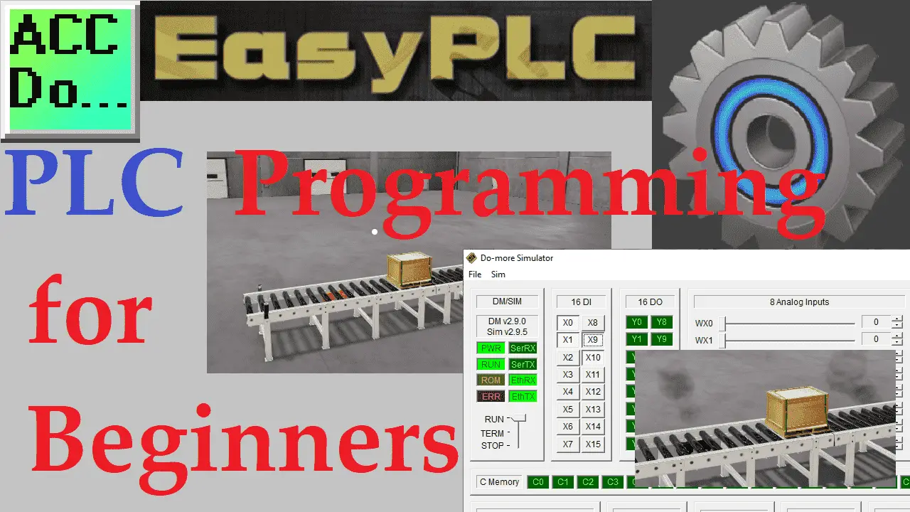
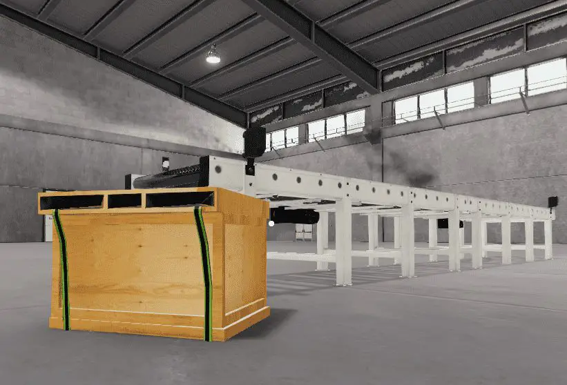
This tutorial is for beginners who are just starting to program PLCs. Using the EasyPLC simple conveyor, we will move a box back and forth on the conveyor. We will learn to write the PLC ladder logic program for this operation.
 Using the five steps to PLC programming development, we will determine what must be done, look at the inputs and outputs, develop the sequence of operation, program the conveyor belt, and test our program. The EasyPLC machine simulator is part of the EasyPLC Software Suite. This package is an excellent way to learn PLC programming without the worry of damaging equipment. We will be programming with the free Do-More Designer PLC software. The Easy machine simulator will be communicating with the Do-More Designer PLC simulator. Let’s get started.
Learn PLC programming the easy way. See below for a 10% discount on this cost-effective learning tool. Invest in yourself today.
Previously we have done the following:
Easy PLC Installing the Software – Video
EasyPLC Software Suite – Quick Start – Video
Click PLC – Easy Transfer Line Programming – Video
Productivity PLC Simulator – Chain Conveyor MS – Video
Do-More PLC – EasyPLC Box Selection Program – Video
Click PLC EasyPLC Gantry Simulator – Video
Click PLC Simple Conveyor EasyPLC – Video
EasyPLC Paint Line Bit Shift – BRX Do-More PLC – Video
Click PLC – EasyPLC PLC Mixer Programming – Video
Click PLC EasyPLC Warehouse Stacker Example – Video
– Operation Video
EasyPLC Machine Simulator Productivity PLC Robotic Cell – Video
EasyPLC Simulator Robotic Cell Click PLC – Video
EasyPLC Simulator Robotic Cell BRX Do-More PLC – Video
– EasyPLC Factory Editor Robotic Cell Additions Video
4 Way Traffic Light PLC Program EasyPLC – Video
Rock Crusher Plant EasyPLC BRX Do-More – Video
Freight Carrier Weighing and Distribution EasyPLC – Video
EasyPLC Machining Center Loading Robots – Video
EasyPLC Palletizing Robot Programming Click PLC – Video
EasyPLC Machine Editor – Design a Simulation – Video
PLC Programming Mixing Tank – EasyPLC / Do-More – Video
EasyPLC Solder Robot PLC Programming – Video
Define the task: (Step 1 – Conveyor PLC Programming Tutorial)
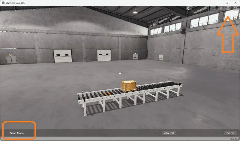
The first step of PLC program development is determining what must be done. A PLC programmer must know everything about the machine before programming. Start the EasyPLC Machine Simulator (MS). Select the start button on the main page or select machines from the main menu on the top of the machines simulator window.
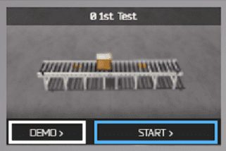
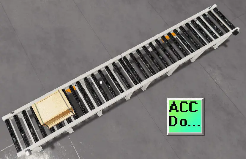
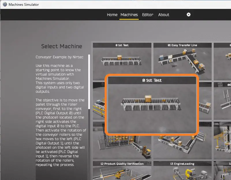 All the available machines will now be displayed. Click on the “0 1st Test”. This is the conveyor that we will be programming. To the left of the screen, information will be displayed. This will indicate what the machine needs to do and the inputs and outputs required for the program.
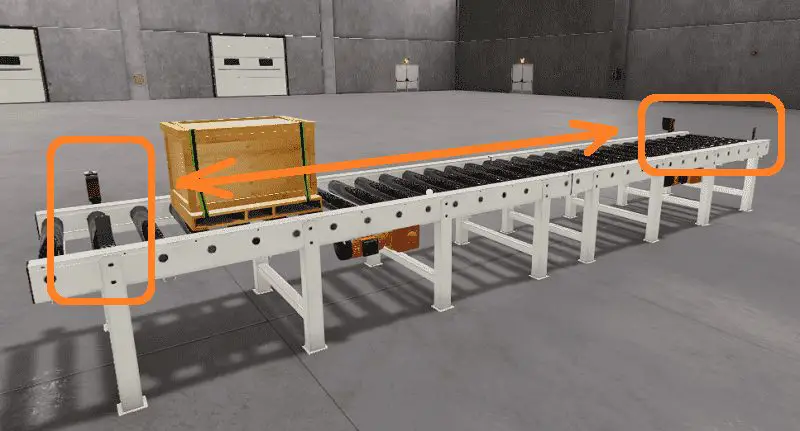
The objective is to move the pallet with the roller conveyor, first to the right, until the photocell on the right side activates. The conveyor rollers will then stop and reverse, so the box moves to the left until the photocell on the left side triggers. The process repeats, moving the roller conveyor again to the right. The pallet will continually move back and forth on the roller conveyor.
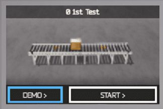 The machine simulator has a demo mode for the built-in machines. This will allow you to watch the operation of the conveyor pallet. Select the demo mode for the “0 1st test”.
 The demo mode will operate, showing you the basics of operation.
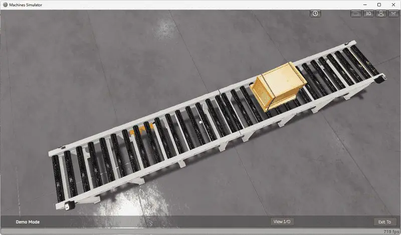 Move around the 3D virtual environment. Three icons on the top of the window will allow you to move around this 3D environment. The first icon is the default selection. This will enable you to move around without bumping into the components. The first-person mode will mimic a person in your 3D learning world. The last icon will automatically show you around this virtual environment. Once we understand what must be done, we can move on to the next development step in the PLC program.
Define the Inputs and Outputs: (Step 2 – Conveyor PLC Programming Tutorial)
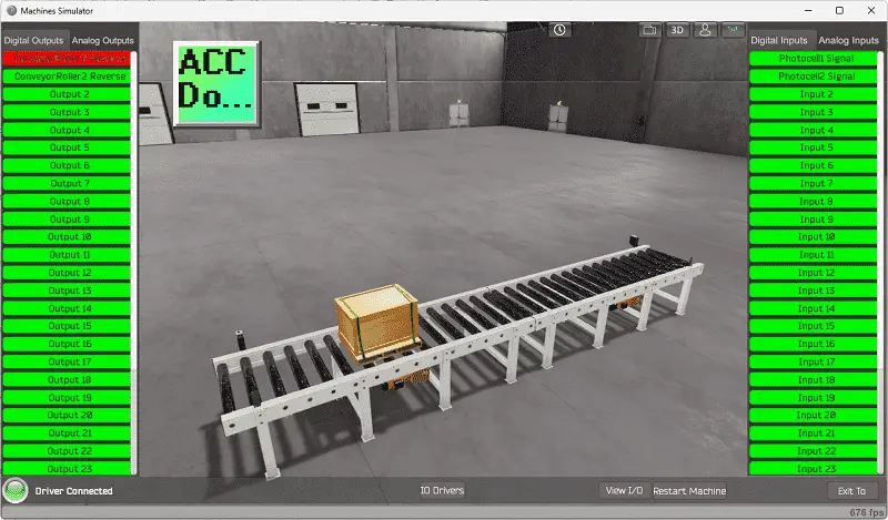
The View IO at the bottom of the machine simulator window will display the inputs and outputs required for this conveyor example. While still in demo mode, you can see the operation of the digital inputs and outputs.
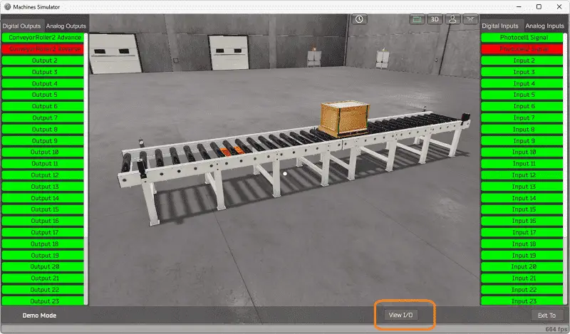 The EasyPLC conveyor example will require two digital outputs and two digital inputs.
Start the machine in Start mode. If you are unsure what output or input is doing, we can manually control them.
 Select the View IO on the bottom middle of the machine simulator window. You can manually run the conveyor application without any control or PLC connection.
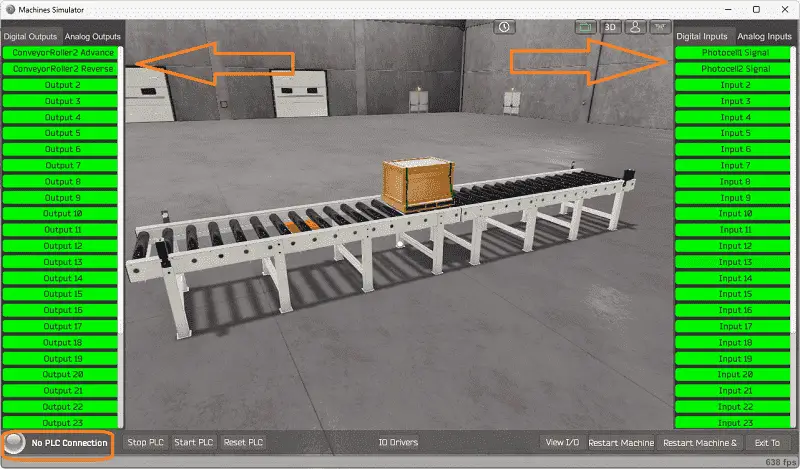 Clicking on the outputs will allow you to turn them on manually. You can then monitor the inputs to see their operation. The restart button on the bottom of the machine simulator window will reset the scene back to the start.
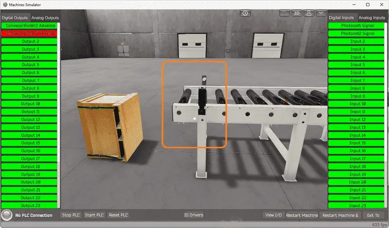
The EasyPLC machine simulator will allow you to program and make mistakes without the destruction of property or equipment.
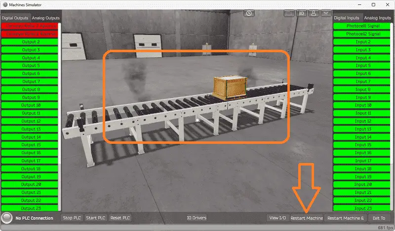 The box will fall off the conveyor belt if the sensor is missed.
 Activating the conveyor’s advance and reverse will burn up the motors. Leaving this on too long will stop the machine from operating. You will now need to reset the machine with the restart button.
We will now look at the setup of the PLC Simulator. This will use Modbus TCP for communication to the EasyPLC MS.
Start the Do-More Designer Software. The BRX Do-More Series will detail how to install and use this free, fully functional Do-More Designer PLC programming software.
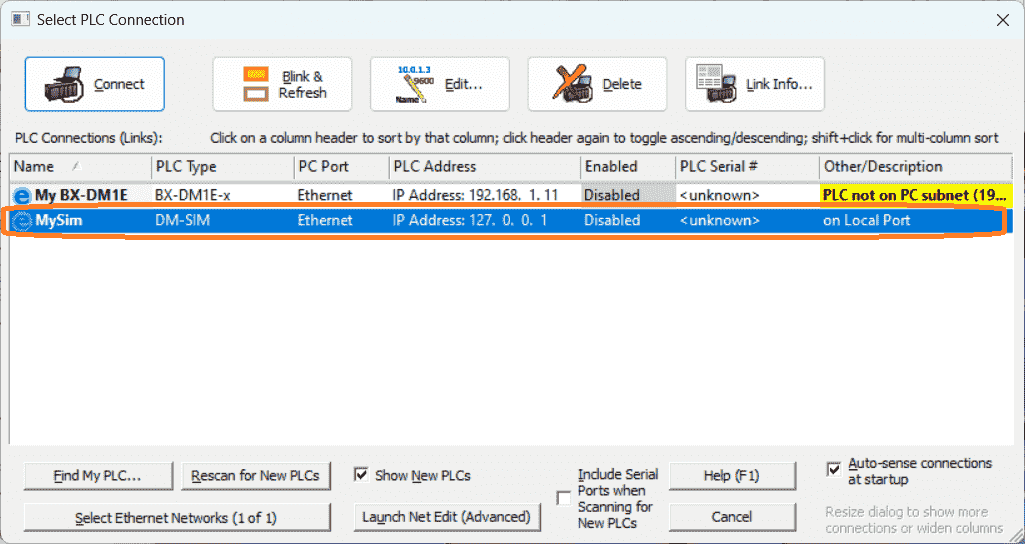
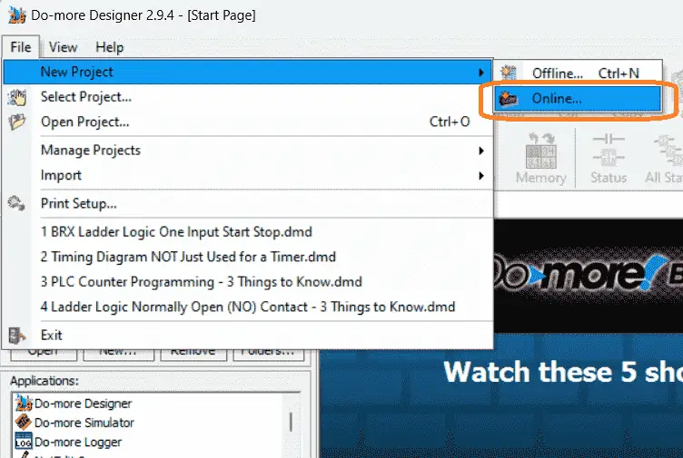 Select “Online…” under New Project in the File option on the main menu. Select “MySim,” which is the Do-More Designer PLC Simulator. Select the connect icon.
 Our Do-More Simulator will now be displayed. This PLC simulator is treated like a PLC. We must program and transfer it into the simulator for it to operate.
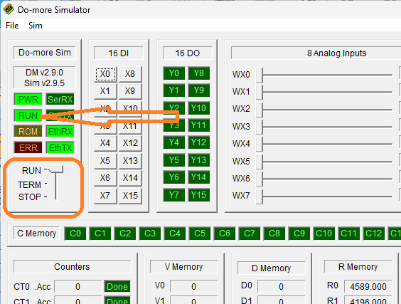
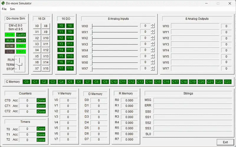 The simulator has three modes. Run will execute the ladder logic program. Terminal mode (TERM) will allow us to control the Run and Stop modes from the Do-More Designer software. The Stop mode will halt the execution of our ladder logic program. We will leave the simulator in TERM mode. You will notice that the simulator will display the digital and analog inputs and outputs and several memory locations. The Ethernet RX and TX signals are flashing. This indicates the simulator is communicating.
Click on our Do-More Designer programming window.
 You will see that we are connected to the simulator at the bottom of the window. It is currently in TERM mode.
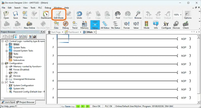
 Select the “Edit Mode” icon on the main menu. This will allow us to start programming our PLC simulator.
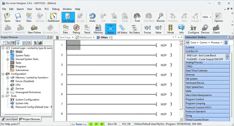
 Under the “Coil/ Bit I/O” heading in the instruction toolbox, double-click on the END instruction. This will put the instruction on the ladder rung that you are currently on.
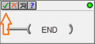
Select the green check mark to verify the location of the end instruction.
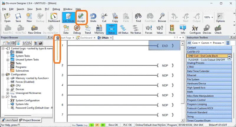 The programmed rung will now have a yellow indication, meaning that we need to accept the changes to our program. Select the “Accept” icon on the main menu.
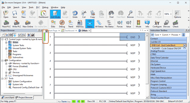 The yellow is now replaced with green and blue indications. The green means that our program has yet to be saved. We will hit the save icon on the main menu. This will prompt us to the name of the saved program. Select OK. Another prompt will now allow us to fill in information about our program. Select OK.
The blue indicator means that the program in the PLC is different from the program currently in the Do-more Designer software.
Press the “Write PLC” icon on the main menu.
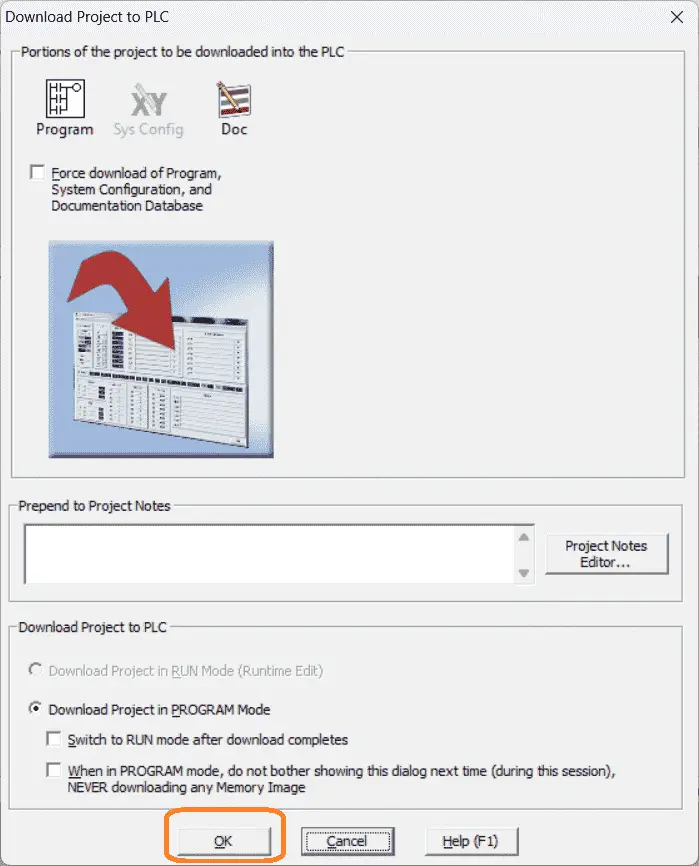 The download project to the PLC window will now be displayed. We will download our project in program mode. Select OK.
Our program has now been written into the Do-more Designer PLC simulator.
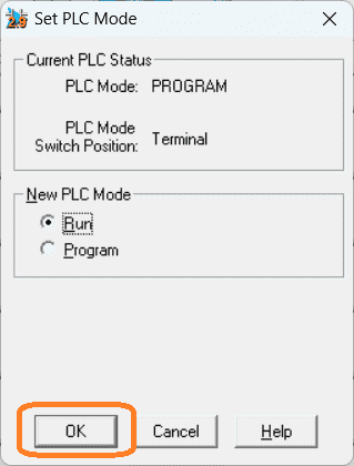 Select the “Mode” icon on the main menu and select run as the new mode. Select OK. The run mode is indicated at the bottom of the Do-more Designer window.
The Do-More family of controllers utilizes a separate memory area for Modbus. MI1 and MI2 will be used for controlling the forward and reverse on the conveyor. MC1 and MC2 will indicate the photocell status.
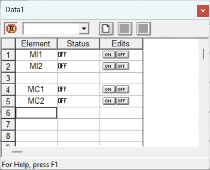 We can use a data monitor to view these bits. Select the “Data” icon on the main menu. This data view window will appear under the project browser. Drag this out to appear in a separate window. Enter the inputs and outputs.
One last thing we need to know before connecting the PLC simulator to the EasyPLC machine simulator is the IP address of the PLC. This is the IP for the computer, but we can also find this out by selecting “System Configuration” under tools in the project browser.
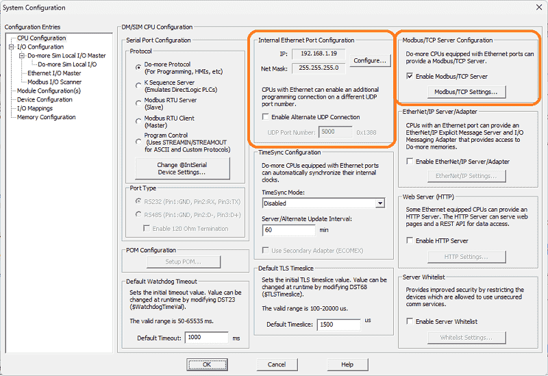 The IP address is shown under the internal Ethernet port configuration. The Modbus/TCP Server Configuration is on the right side of this selection. The enable Modbus/TCP server is on by default. Select OK.
We will connect the inputs and outputs from the EasyPLC machine simulator to the Do-More Designer simulator using Modbus TCP.
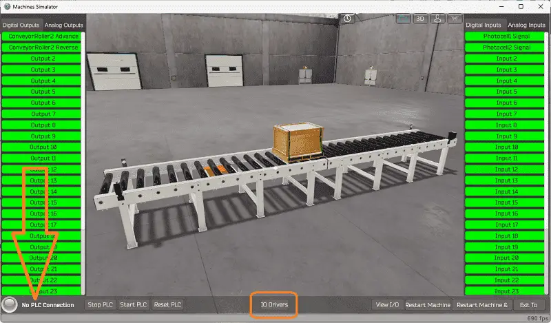
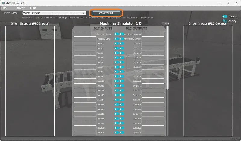
Returning to the machine simulator, you can see that we have no PLC connected in start mode. This is indicated in the bottom left corner. Select IO Drivers on the bottom middle of the screen.
 The EasyPLC driver is selected by default. Select the down arrow on the driver’s name. Under the driver pull-down menu, select “ModBusDriver.” This driver will communicate Modbus TCP (Ethernet) and Modbus RTU (Serial).
 Select the configure button.
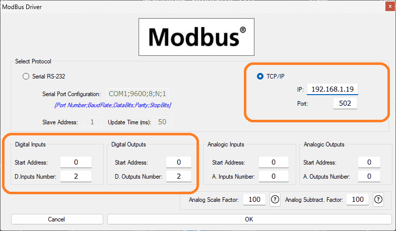
 We can now enter the information for our Modbus driver. Select TCP/IP. This means the computer’s Ethernet port will communicate with the PLC.
The digital inputs from MS to the Do-More PLC will be 100001 and 10002. This will start at address 0 due to the offset of 1. Digital outputs from MS to the Do-More PLC will be 1 and 2. This will begin at address 0 due to the offset of 1. Select the OK button.
 You will now see the inputs and outputs specified for the Modbus driver.
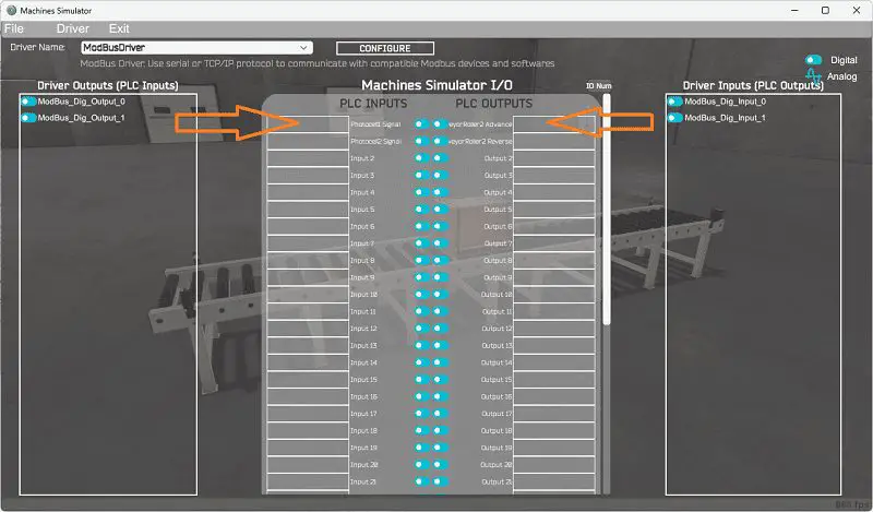 We can manually assign the driver outputs to the PLC inputs and the driver inputs to the PLC outputs. However, the automatic assignment works well and will save you time.
Select Automatic Assignment from the driver option in the main menu.
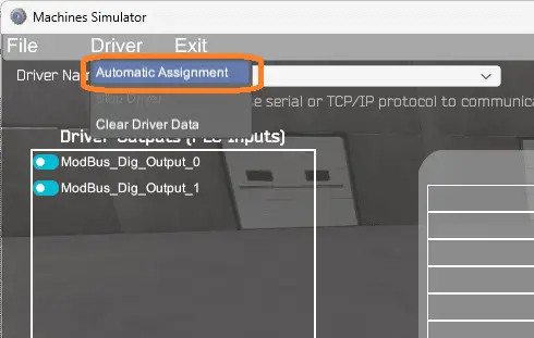 This will automatically assign the PLC IO to the Machine Simulator IO.
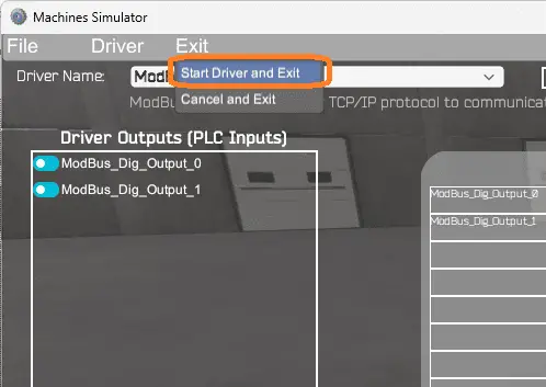 Select start driver and exit from the main menu.
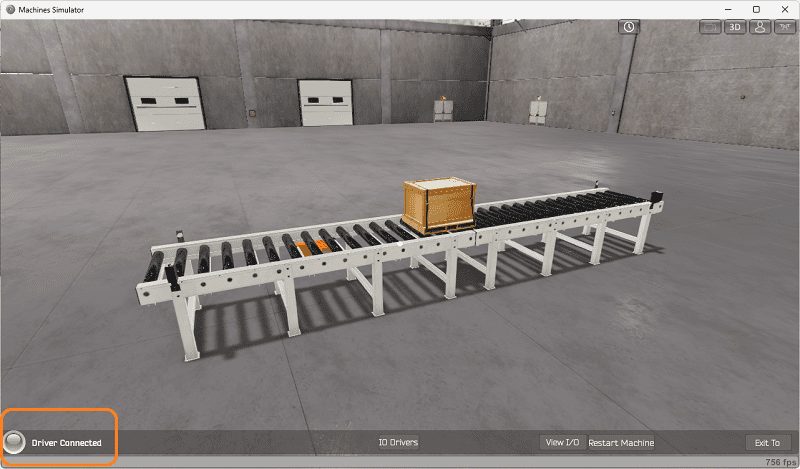 On the bottom left side of the window, you will see that the driver communicates to the PLC with the green light. Select view IO to know the input and output status of the machine simulator.
We can test the PLC’s inputs and outputs by calling the Data View window from the Do-more designer software. We are now ready to move on to the next step.
Watch the video below to see this in operation.
The following table will define the inputs and outputs (IO) and Modbus addresses in the Do-More PLC simulator that we will use for this program.
| Digital Type | Description | Do-More PLC Modbus Address | Machine Simulator Modbus Address |
| PLC Output – MS Input | Conveyor_Advance | MI1 – 10001 | 0 |
| PLC Output – MS Input | Conveyor_Reverse | MI2 – 10002 | 1 |
| PLC Input – MS Output | Con_Adv_Limit | MC1 – 1 | 0 |
| PLC Input – MS Output | Con_Rev_Limit | MC2 – 2 | 1 |
Note: The machine simulator will be offset by one of the Modbus Addresses. See the video below for the demo mode and determining inputs and outputs.
Develop a logical sequence of operation: (Step 3 – Conveyor PLC Programming Tutorial)
A flow chart, sequence table, or detailed sequence description is used to understand the process that needs to be controlled.
You may think this is like step 1, but it will go into more detail and utilize all the inputs and outputs that need to be programmed.
It must also answer questions like the following:
What happens when electrical power or pneumatic air is lost? What happens when the input/output devices fail? Do we need redundancy?
This step is where you will spend most of your time. Understanding everything about the operation will save you time. It will help prevent you from continuously rewriting the PLC program logic. Knowing all these answers upfront is vital in developing the PLC program. Our simple system will help you understand the thinking behind writing a ladder logic program.
 Upon powering up the PLC, and the end sensors do not detect a box, move the conveyor in the forward direction. A box on the conveyor belt will be moved back and forth. Stop the conveyor’s forward movement when the forward sensor detects the box. Wait for 1 second, then move the conveyor in the reverse direction. Stop the conveyor’s reverse movement when the reverse sensor detects the box. Wait for 1 second, then move the conveyor in the forward direction again. This cycle will continually cycle. The one-second delay at each end of the conveyor will ensure that both outputs are not on simultaneously.
A PLC programmer must know how everything about the sequence and operation of the machine before programming.
Ask questions or View existing documentation to ensure you know the logical steps to the machine’s operation.
Develop the PLC program: (Step 4 – Conveyor PLC Programming Tutorial)
Writing the ladder logic code for the PLC example will be the next step in our program development. The BRX Do-More Series will provide additional information on the Do-More Designer and PLC Simulator. We will be using the online programming of the PLC simulator. As our program is developed, we can see its operation.
In step 2, we establish communication between the EasyPLC machine simulator and the PLC simulator. This used Modbus TCP (Ethernet), and we called up the MI1 and MI2, which were the conveyor forward and reverse directions. MC1 and MC2 were the sensors for the direction. Manually turning these bits on and off, we moved the pallet. This proved our inputs and outputs were functioning correctly.
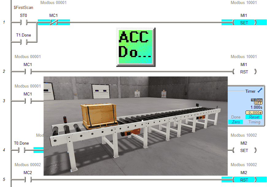
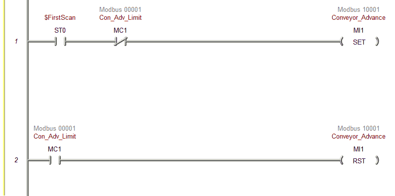 The first rung we write will control the forward direction (MI1). We will use the Set and Reset instructions to set logic for each condition.
The first scan of the PLC will turn on the system bit ST0. Not MC1, the forward sensor will be “AND” together with the first scan and set the forward direction. This means the forward direction will not be set when the forward sensor detects an object.
MC1 will be used to reset the forward direction on rung 2.
Online programming is a great feature but must be used with caution on physical equipment. We can save the program and write to the PLC. The write will happen while the PLC is running. What happens is that the scan is held, and new lines are inserted into the program. When the scan is released, it will be running the new program.
If we switch our PLC simulator to stop mode and back to run, our pallet will move forward and stop at the sensor. This is due to the first scan flag starting the conveyor in the forward direction.
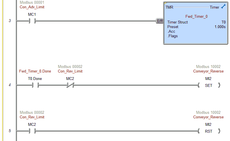 We can now add our 1-second delay timer when the forward photocell is activated. This will be timer 0.
Timer 0 done bit will be in series with the normally closed reverse photocell. This will set the reverse conveyor direction.
When MC2 (reverse photocell) is on, this will reset the reverse conveyor.
Save the program and write to the PLC. The timer will time and send the pallet the opposite way. It will stop when the reverse photocell is activated.
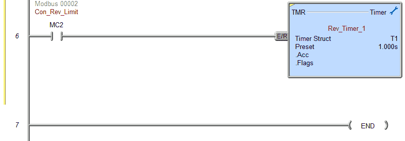 We will add another 1-second delay timer when the reverse photocell is activated. This will be timer 1.
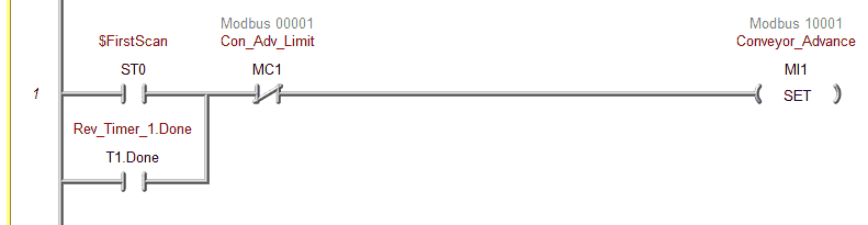 Timer 1 done bit is placed in parallel with the first scan bit of the PLC on rung 1.
Save the program and write to the PLC.
Our program is now complete. The pallet is moving back and forth.
Documentation is one of the essential things with PLC programming. Knowing what the program is doing years after you develop the logic can be critical.
On the main menu, select Tools | Documentation Editor… All the elements that have been used in the program are listed. We can assign names to each of them. You can also call the document editor using the Ctrl + D keyboard shortcut.
Watch the video below to see this PLC program in action.
Test the program: (Step 5 – Conveyor PLC Programming Tutorial)
Ensure that the PLC is in run mode. We can see the operation of our simple conveyor.
 Test the program under many conditions. Stop the pallet at each end of the conveyor. What will happen when the PLC logic is started again? Change the timer set value to 500 milliseconds at each end. Simple modifications like this are easily done using online programming with the PLC.
Move the box around and trick the sensors. This is all a part of program testing.
 You may have to rewrite your ladder logic code if something unexpected happens. This may even mean that you will have to change your operation sequence.
 To help you practice and learn more, here are a few challenges for this simple conveyor.
– Add a start, and stop control station to the EasyPLC machine. Add the controls to your existing PLC ladder logic.
– Count the number of times the box has moved back and forth.
– If the box falls off the conveyor, detect this and stop the conveyor.
 Download the Do-More Designer PLC sample program here.
Watch the video below to see the five steps of program development applied to the simple conveyor. The machine simulator is one of the best applications to help you learn PLC programming.
EasyPLC Software Suite is a complete PLC, HMI, and Machine Simulator package. This PLC learning package includes the following:
Easy PLC – PLC Simulation allows programming in Ladder, Grafcet, Logic Blocks, or Script.
HMI System – Easily create a visual human-machine interface (HMI)
Machine Simulator – A virtual 3D world with real-time graphics and physical properties. PLC programs can be tested using EasyPLC or through other interfaces. (Modbus RTU, TCP, etc.)
Machine Simulator Lite – Designed to run on Android Devices.
Machine Simulator VR – Virtual Reality comes to life so you can test, train or practice your PLC programming.
Purchase your copy of this learning package for less than USD 75 for a single computer install or less than USD 100 to allow different computers.
Receive 10% off the price by typing in ACC in the comment section when you order. http://www.nirtec.com/index.php/purchase-price/
Learn PLC programming the easy way. Invest in yourself today.
Watch on YouTube: PLC Programming – A Tutorial for Beginners
If you have any questions or need further information, please contact me.
Thank you,
Garry
If you’re like most of my readers, you’re committed to learning about technology. Numbering systems used in PLCs are not challenging to learn and understand. We will walk through the numbering systems used in PLCs. This includes Bits, decimals, Hexadecimal, ASCII, and Floating points.
To get this free article, subscribe to my free email newsletter.
Use the information to inform other people how numbering systems work. Sign up now.

The ‘Robust Data Logging for Free’ eBook is also available for free download. The link is included when you subscribe to ACC Automation.