In this tutorial, I will show you how to connect the ACC PLC Simulator’s 3D Control Panel Scene to the BRX Do-More PLC using Modbus TCP over Ethernet. We will use the Do-More Simulator that comes built into the Do-More Designer programming software. This means you don’t need any physical hardware. You will write real PLC ladder logic in Do-More Designer, run it on the built-in simulator, and control the 3D panel scene over Modbus TCP — all on a single PC.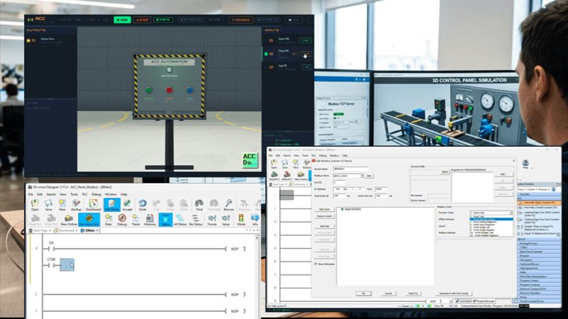
This is one of the most practical ways to learn both PLC programming and Modbus TCP communication simultaneously. Let’s get started.
What You Need
Here is what you need before we begin. All of this software is free.
- A Windows PC — Windows 10 or newer
- Do-More Designer — Free programming software for the BRX Do-More PLC series. Download from the Automation Direct Website. The software includes the Do-More Simulator, which runs a full PLC emulation on your PC.
- Node.js — Free runtime from nodejs.org. Download the LTS version and install with all defaults. You only need to do this once.
- The ACC Modbus Bridge — A small Node.js program that connects the browser-based 3D scene to a Modbus TCP master. You download this directly from within the scene.
- A web browser — Chrome, Edge, or Firefox
How It Works
The Do-More Simulator acts as a Modbus TCP Client (Master). It reads inputs from the bridge and writes outputs to the bridge. The ACC Modbus Bridge is a Node.js application that acts as the Modbus TCP Server (Slave). It translates between Modbus TCP and the WebSocket connection that the browser-based 3D scene uses. The 3D Control Panel Scene runs in your browser. It sends pushbutton states to the bridge and receives output commands back.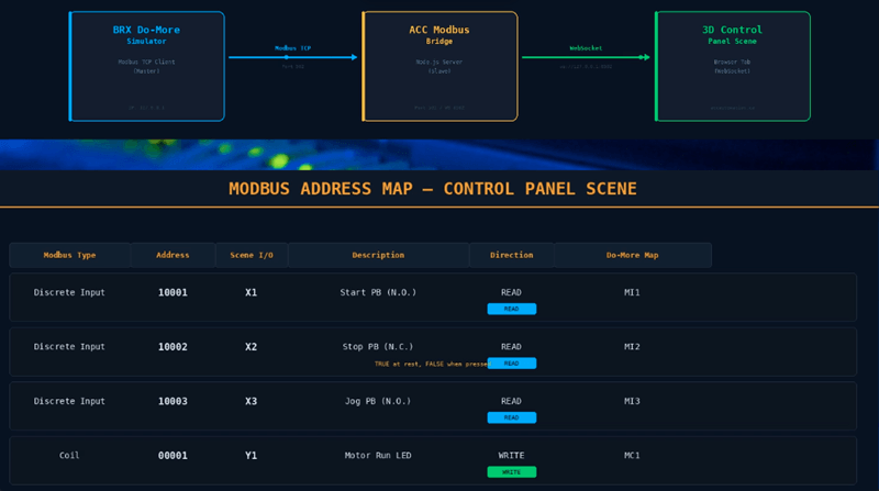
The data flow: Do-More Simulator → Modbus TCP (port 502 or 5020) → ACC Modbus Bridge → WebSocket (ws://127.0.0.1:8502) → 3D Control Panel Scene (browser).
All three components run on the same PC. No network wiring required.
Modbus Address Map
| Modbus Type | Modbus Address | Scene I/O | Description |
|---|---|---|---|
| Discrete Input | 10001 | X1 | Start pushbutton (N.O.) |
| Discrete Input | 10002 | X2 | Stop pushbutton (N.C.) |
| Discrete Input | 10003 | X3 | Jog pushbutton (N.O.) |
| Coil | 00001 | Y1 | Motor Run pilot light |
Discrete Inputs are read-only. The scene drives these based on the 3D pushbutton states. Coils are writable. The PLC writes to Coil 1 to turn the motor run pilot light on or off.
Step 1 — Install Node.js (3D Scene Modbus)
Go to nodejs.org and download the current LTS version. Node.js 16 or higher is required. Run the installer and accept all defaults. When it finishes, the node and npm commands will be available from the command prompt. You can verify by opening a command prompt and running node –version. You only need to do this once. Node.js is required for the ACC Modbus Bridge.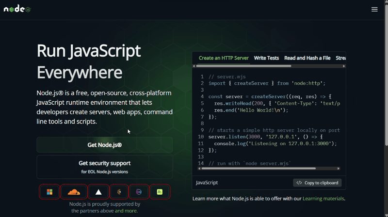
Step 2 — Download and Install the ACC Modbus Bridge (3D Scene Modbus)
Open the 3D Control Panel Scene in your browser at accautomation.ca/simulator/. Navigate to the Control Panel scene and look for the MODBUS button in the scene toolbar. Click it to open the Modbus configuration strip.
Click the download icon to save acc-modbus-bridge.zip to your PC. Extract the zip file to a folder. I recommend something simple like C:\ACC\modbus-bridge.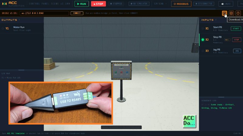
If you plan to use Modbus RTU over serial, plug in your USB-to-RS-485 or USB-to-RS-232 adapter now, before running the installer. Open Device Manager in Windows and expand the Ports (COM and LPT) section to confirm the COM port number assigned to your adapter. You will need this COM port number when the installer asks for your serial port. Common adapters include the AutomationDirect USB-485M and any FTDI-based USB-to-RS-485 converter. The serial device must be connected before you run the installer so it can detect the available ports.
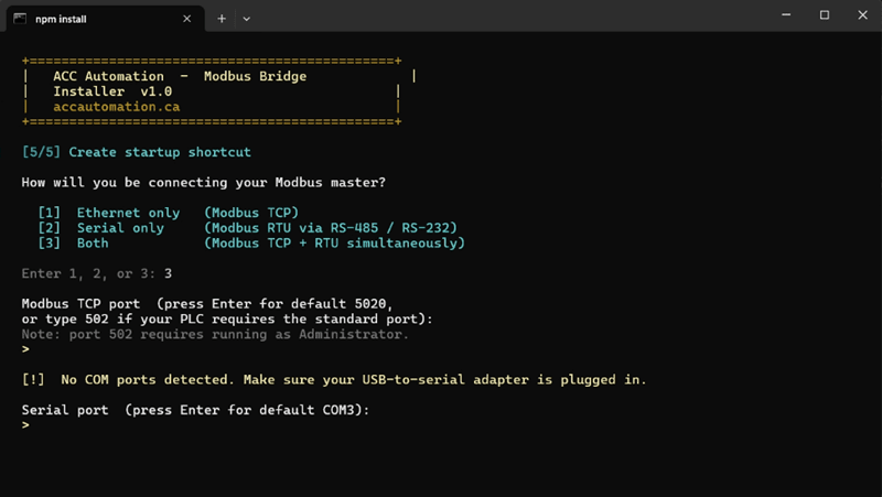
Double-click install.bat (Windows) or install.command (macOS) to run the installer. The installer will check for Node.js, install the required packages, and then ask you a series of questions about your Modbus configuration. Based on your answers, it will automatically create desktop shortcut icons to start the bridge. You can choose Modbus TCP, Modbus RTU, or both.
Step 3 — Start the ACC Modbus Bridge (3D Scene Modbus)
Double-click the desktop shortcut that the installer created to start the bridge. 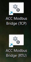
A terminal window will open showing the bridge banner with the Modbus TCP port, WebSocket port, and supported function codes. Leave this terminal window open for the communication to happen.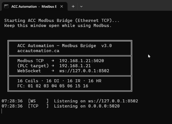
If you need to start the bridge manually, open a command prompt in the bridge folder. Here are the commands for each mode.
Modbus TCP (Ethernet):
node acc-modbus-bridge.js --modbus-port 502Note that port 502 requires running the command prompt as Administrator. If you do not want to run as Administrator, use port 5020 instead:
node acc-modbus-bridge.js --modbus-port 5020Modbus RTU (Serial):
node acc-modbus-bridge.js --mode rtu --serial-port COM3Replace COM3 with the COM port shown in Device Manager for your USB adapter.
Both TCP and RTU simultaneously (shared data image):
node acc-modbus-bridge.js --mode both --serial-port COM3 --modbus-port 5020
Step 4 — Connect the 3D Scene to the Bridge (3D Scene Modbus)
Go back to the Control Panel Scene in your browser. Click the MODBUS button in the toolbar. The scene will attempt to connect to the bridge on 127.0.0.1:5020. If the bridge is running, the connection indicator will show MODBUS LINKED.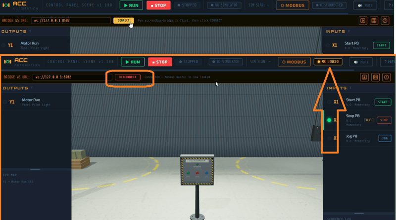
At this point, the 3D scene is connected to the bridge. Every time you press a pushbutton on the 3D panel, the bridge updates its Modbus Discrete Input registers. Any time a Modbus master writes to Coil 1, the bridge sends the update to the scene, and the motor run pilot light responds.
Step 5 — Install Do-More Designer
Download Do-More Designer from the AutomationDirect website. The software is completely free with no license required. It includes the Do-More Simulator, which behaves exactly like a physical BRX Do-More PLC.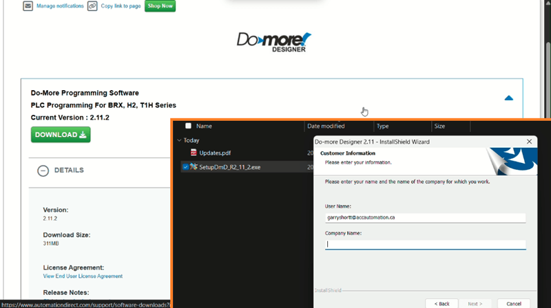
Previously, we have covered installing the Do-More Designer software here: Installing the Software
Step 6 — Create a New Simulator Project
Open Do-More Designer. 
Select New on the main menu ribbon. Select Do-More Simulator as the hardware type. Name it ACC_Panel_Modbus. Select OK.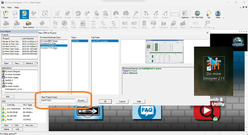
Step 7 — Start the Do-More Simulator
Select the Do-More/Sim icon on the main menu ribbon. The simulator starts in a separate window. Return to Do-More Designer and select Write PLC to transfer your project.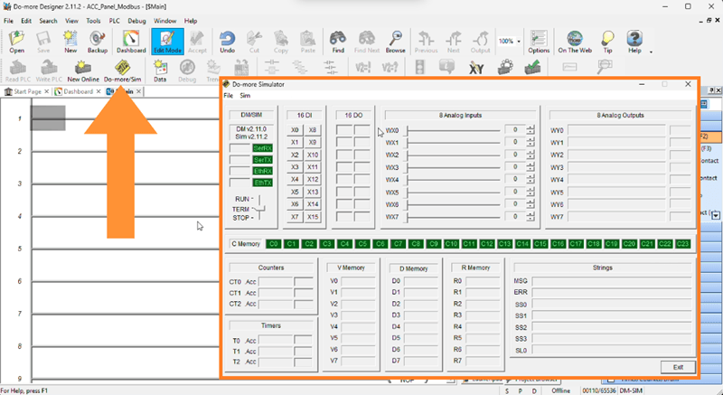
Step 8 — Configure the Modbus TCP Client Device
Select System Configuration from the main menu under PLC, or find it under the Tools menu in the Project Browser. The System Configuration window will be displayed.
Navigate to Devices and add a new device. Select Modbus TCP Client as the device type. Configure the following settings:
| Setting | Value |
|---|---|
| Device Name | ACC_Panel |
| IP Address | (IP address of the PC running the bridge) |
| TCP Port | 502 (or 5020) |
| Unit ID | 1 |
To find the IP address of the PC running the bridge, open a command prompt and run ipconfig. Look for the IPv4 Address under your Ethernet or Wi-Fi adapter. It will be something like 192.168.1.100. Use that address in the device configuration. Even when the bridge and the Do-More Simulator are running on the same PC, use the actual IP address rather than 127.0.0.1 because the Do-More Simulator communicates through the PC’s Ethernet port. | Unit ID | 1 |
See the video below.
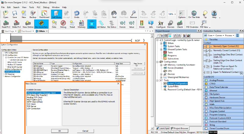
This tells the Do-More Simulator to connect to the ACC Modbus Bridge running on your local machine.
Step 9 — Configure the Modbus I/O Scanner
The easiest way to handle Modbus communication is to use the Do-More Modbus I/O Scanner. This handles all the reading and writing automatically in the background, independent of your PLC scan time. No ladder logic is needed for the communication itself.
In the System Configuration under the device you just created, add the following I/O scanner entries.
Read Discrete Inputs (Scene pushbuttons to PLC): Set the source type to Discrete Input, source address to 1, count to 3, and destination to C0. This reads Discrete Inputs 1 through 3 from the bridge and maps them to C0, C2, and C3 in the Do-More PLC. MI1 is Start, C1 is Stop, C2 is Jog.
Write Coils (PLC to Scene pilot light): Set the source to C100, count to 1, destination type to Coil, and destination address to 1. This writes C100 from the Do-More PLC to Coil 1 on the bridge. When C100 is ON, the motor run pilot light turns on in the 3D scene.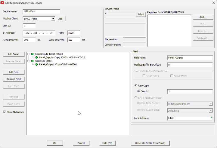
Write the updated configuration to the simulator.
Step 10 — Write the Ladder Logic
Now we write the Start/Stop/Jog program in Do-More Designer. This is the same logic concept as the ACC PLC Simulator default program, but using Do-More addressing.
Rung 0 is your Start/Stop with Seal-In. Use C0 (Start) as a normally open contact. Add C100 (Motor output) in parallel for the seal-in. Add C1 (Stop) as a normally open contact in series. The output is C100.
Note that C1 is your Stop pushbutton. The panel scene sends the physical N.C. state, meaning C1 is TRUE at rest and goes FALSE when pressed. So you use a normally open contact on C1. This is the same approach as the ACC PLC Simulator default program, where XIC X2 reads the N.C. bit directly.
For the Jog interlock, add C2 (Jog) as a third parallel branch to the first rung. Then add a second rung in which C2 drives an internal bit, such as C200. Back in the first rung, add a normally closed contact on C200 in series with the C100 seal-in branch. This blocks the seal-in during Jog, exactly like C1 does in the ACC PLC Simulator default program.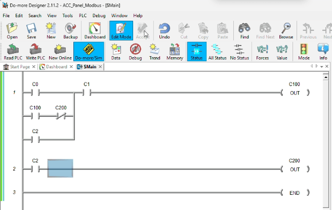
Transfer the updated program to the simulator using the Write PLC button.
Step 11 — Put the Simulator in Run Mode
In the Do-More Simulator window, switch to Run mode. The Modbus I/O Scanner begins polling immediately. You should see activity in the bridge terminal.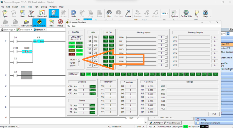
Step 12 — Test the Connection (3D Scene Modbus)
Test Start: Press the green Start button on the 3D panel. C0 goes TRUE. C100 energizes. The pilot light turns on. Release — the seal-in holds.
Test Stop: Press the red Stop button. C1 goes FALSE. C100 turns OFF. Pilot light turns off.
Test Jog: Press and hold the blue Jog button. C100 energizes. Release — C100 drops immediately. No latch.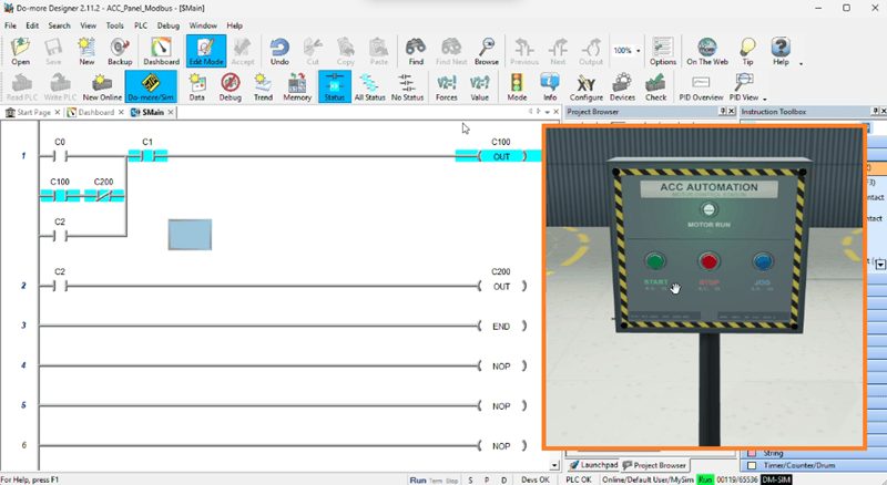
You are now running a real BRX Do-More PLC program on the simulator, communicating over Modbus TCP to a 3D industrial scene in your browser. Watch the video below to see this in operation.
Troubleshooting
Here are common issues and how to fix them.
Bridge will not start with the port in use error: Another program is using the port. Try a different port number, such as 5020 or 5502.
Scene will not connect to the bridge: Make sure the bridge is running and that it shows “Listening on 0.0.0.0:5020” in the terminal. Check that you do not have another scene tab already connected. Only one scene can connect at a time.
Scene not responding to PLC outputs: Make sure the 3D scene is NOT in Run mode. If the scene is in its own standalone Run mode, the PLC cannot control it. The scene must be in Modbus mode for the external PLC to drive the outputs. Stop the scene’s internal run mode before connecting via Modbus.
Do-More Simulator will not connect to the bridge: Verify the IP address matches the PC running the bridge. Run ipconfig to confirm the correct address. Make sure the port matches what the bridge is listening on. Check Windows Firewall. You may need to add an inbound rule to allow TCP traffic on your bridge port.
Inputs not updating: Make sure the I/O Scanner is configured correctly with the right Modbus addresses. Discrete Inputs start at address 1 not 0. Confirm the bridge terminal shows polling activity.
What You Learned!
In this tutorial, you set up a complete Modbus TCP communication link between the BRX Do-More Simulator and a 3D industrial scene. You installed the ACC Modbus Bridge, configured a Modbus TCP Client device in Do-More Designer, used the I/O Scanner for automatic data exchange, and wrote a Start/Stop/Jog program that controls a 3D control panel over Ethernet.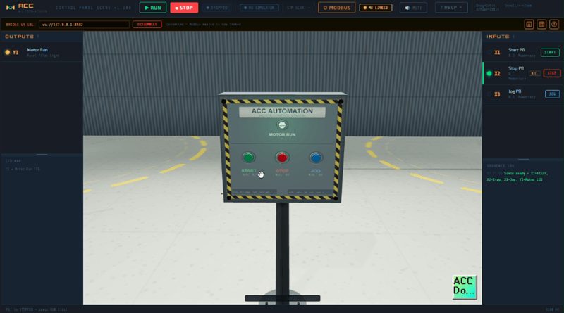
This same setup works with any Modbus TCP master. You can use a physical BRX PLC, a Click PLC, a Productivity Series PLC, or any other PLC brand that supports Modbus TCP client functionality. The bridge looks like any other Modbus TCP slave device on the network.
In the previous BRX Do-More series, we have covered the complete range, from hardware to communication. You can find my entire BRX Do-More PLC series on ACC Automation, covering everything from installation to Modbus communication to AdvancedHMI. Click here. Click here to learn how to use the Free Browser-Based ACC PLC Simulator.
Our BRX Do-More Series: accautomation.ca/series/brx-do-more-plc/
Do-More Designer Software: Free Download from AutomationDirect
Try the ACC PLC Simulator Scenes: accautomation.ca/simulator/
What’s Next
The ACC PLC Simulator is actively being developed. New scenes, new instructions, and new features are being added regularly. If you have a suggestion for a scene or feature, leave a comment or reach out through the contact page.
Watch the video below for a walkthrough of the simulator in action.
Watch on YouTube:
ACC PLC Simulator – How to Use the Free Browser-Based PLC Trainer
ACC PLC Simulator 🖥️— Learn the Control Panel Scene Tutorial Now!
You Don’t Need Hardware to Control 3D PLC Scenes!
If you have any questions or need further information, please contact me. Thank you, Garry