
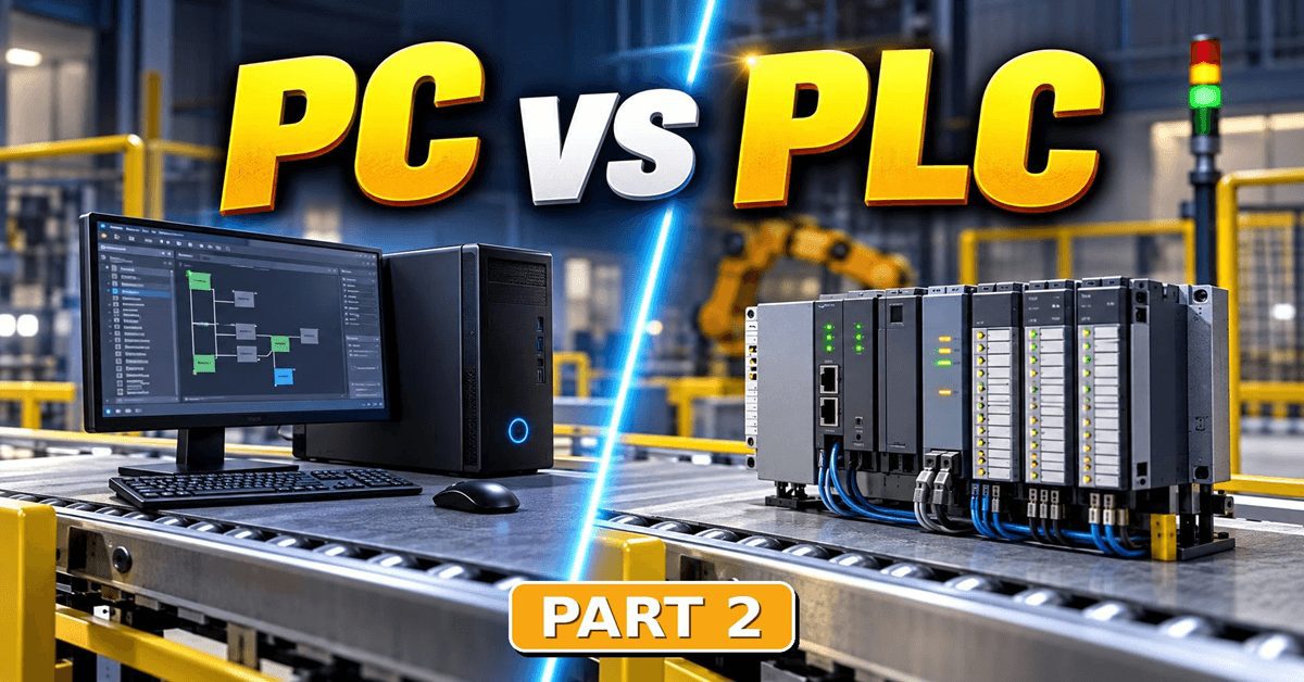
This PLC hardware PLC vs PC article was written by Chris Urban, an automation educator and PLC trainer with over 40 years of hands-on experience. Find Chris on YouTube and LinkedIn. — CU
This is the second part of our PLC vs PC series. If you missed it, start with Part 1, where we looked at the difference between the microprocessor and the microcontroller. Here we put a PLC vs PC comparison side by side, using their block diagrams.
Watch it on YouTube:
PLC Hardware Explained: PC vs PLC Diagram Inside
If you missed it, here is Part 1:
PLC Hardware: PC Brain vs PLC Brain – Video
Let’s Look at a Standard PC Block Diagram
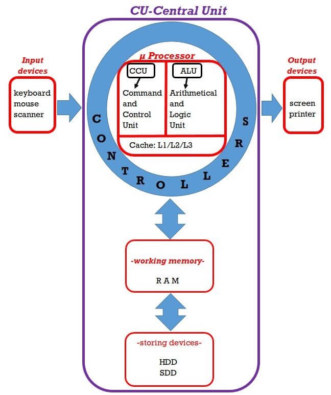
Simplified PC block diagram. The purple outline marks what sits inside the central unit.
Diagram courtesy Chris Urban.
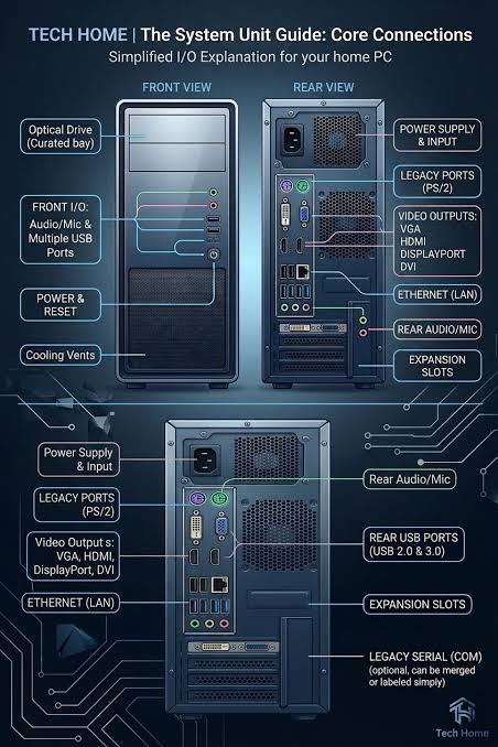
All modern microcomputers are based on a similar internal architecture. To make the PLC vs PC distinction as obvious as possible, I took the liberty of simplifying the computer block diagram:
- I omitted the power supply. Each PC component has specific voltage and current needs. The CPU may ask for around 1.8V, the memory modules around 1.1 to 1.5V, the fans 12V, and so on.
- To keep the relationship between the CPU, inputs and outputs straightforward, I left the I/O systems — sound, video, network card — aside.
With this setup, the first thing we notice is that the microprocessor is a bit like a queen bee: completely isolated from the outside world. To communicate with the RAM, storage drives, communication ports, sound or video systems, Ethernet, WiFi and PCI slots, the CPU is surrounded by all kinds of controllers. These are designed to manage the protocols governing each component — so the processor can be left alone to do what it does best: math and giving instructions.
“What do you call a hardware developer who accidentally plugs 5V logic into a 3.3V UART port? A serial killer.”
Keep in mind what the central unit contains — follow the purple outline on the sketch: the CPU with its controllers, the RAM and the internal storage devices.
And now we reach the essential connecting feature. All the input devices — keyboard, mouse, scanner — are outside the central unit box. So are the standard outputs, like the monitor and the printer.
Note: remember to set aside what look like exceptions to that basic block diagram. A couple worth recalling:
- External monitor connectors are provided, but for practical reasons laptops have their screen already attached to the central unit.
- For the same laptops, it is convenient to have the trackpad and keyboard attached to the central unit too.
- To avoid wiring clutter, airport terminal keyboards are always on the touch screen.
PLC vs PC: The PLC Block Diagram
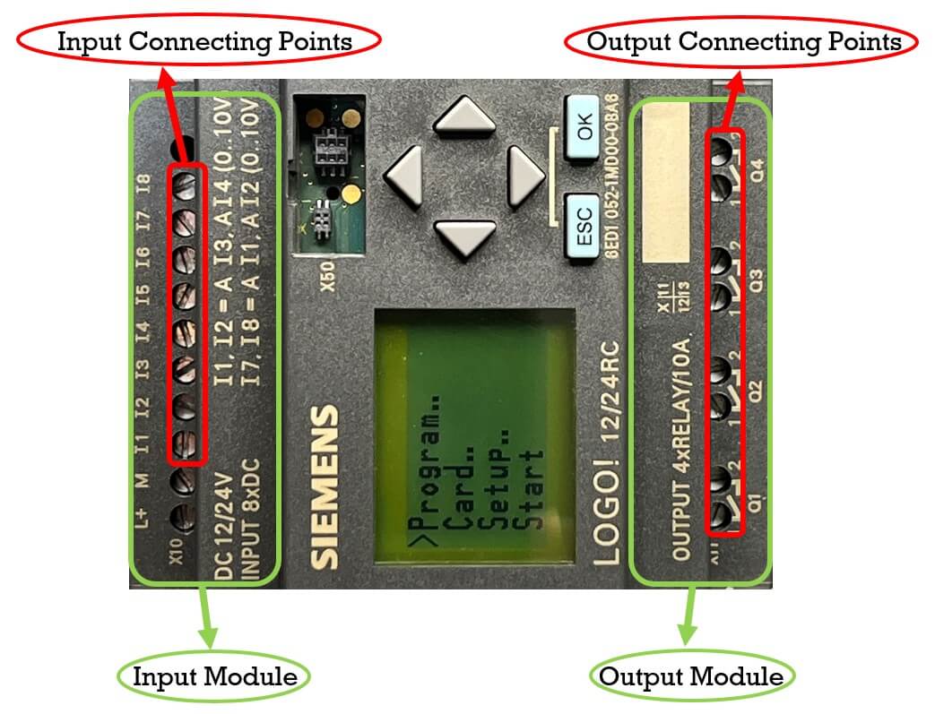
Below is a compact PLC. When the number of points is small — say 6 inputs and 4 outputs — we call it a programmable relay. It does not really matter; it works like any other PLC.
The internal block diagram of a classical PLC can be reduced to this.
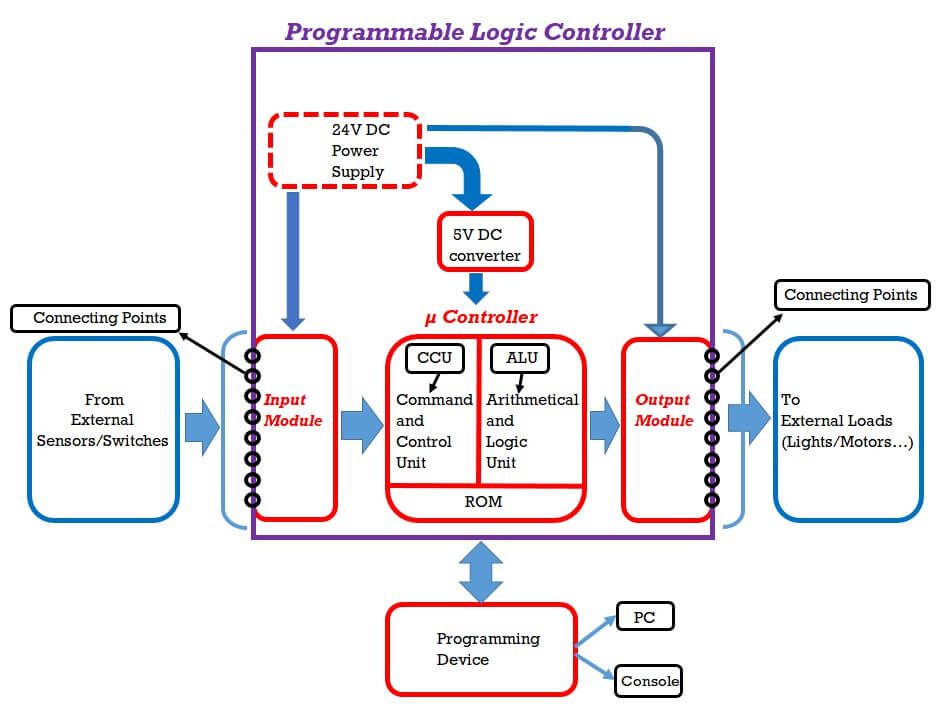
Diagram courtesy Chris Urban.
Like the central unit of the PC, the purple outline surrounds what is in the box. But I will go straight to the essential point: unlike a central unit, the input module and the output module are both inside the box, not outside.
You may be surprised to see the power supply drawn in the box. Notice it is in a dotted line, which means its presence there is optional. Most PLCs have the power supply already included, so you just attach a power cord to the wall AC outlet. Some — like the compact Siemens LOGO above — do not. If placed in a control cabinet with other equipment, such a PLC can be supplied with 24VDC from an existing source, so there is no need to duplicate it.
Much more interesting is the little 5VDC converter, which is not optional. It actually ties all the blocks in the PLC diagram together.
The first thing to know is that the microcontroller is a TTL IC.
On the left side of the input module you can see screws — also visible on the LOGO picture — where industrial switches and sensors from the factory line are connected. Depending on the application, those sensors may run at 12V or 24VDC, usually not 5V. So the real purpose of the input module is to convert the outside signals into TTL information — because that is the only kind the microcontroller can understand and process.
Similarly, as the result of the program execution — remember, the microcontroller already has the program stored in its own internal ROM — the data goes to the output module in TTL format.
But what do we connect to the screws of the output module? We connect 12 or 24V motors, lights or pneumatic valves — or even 120VAC lights and other high-voltage loads. So the output module’s task becomes clear: to transfer TTL signals from the microcontroller back to the outside world, in whatever format that specific load requires.
This is why both the input and output modules are inside the PLC box, not outside. When you look back at the two block diagrams side by side, the PLC vs PC distinction should jump out at you.
Note 1: In what direction does the information travel among the components? Easy to see — it is shown by the blue arrows.
Note 2: The only other device outside the PLC box is the programming device — either a computer through its software app, or a programming console, a kind of specialised keyboard that provides all the instructions without needing a laptop. The only language implemented on such a console is the IL (Instruction List). As mentioned in the previous article, the Instruction List was recently deprecated, so neither the console nor the IL is available on new PLCs.
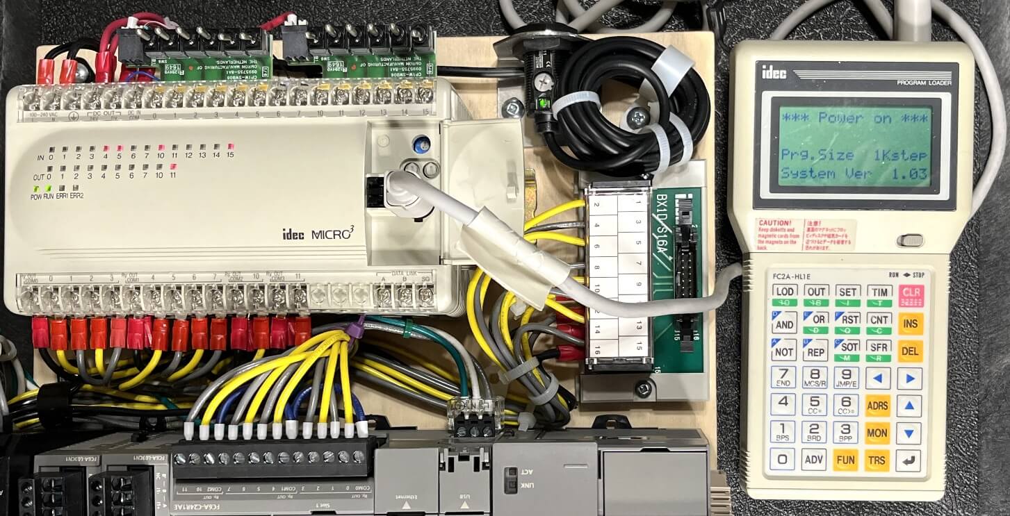
In a way it is an unfortunate outcome for both. The IL was a wonderful tool for learning the practical application of logic gates, along with all the intricacies between virtual and real relay contacts and coils. But it is too late to complain — the evolution of technology has no mercy.
Two Closing Thoughts on Technology
“If you’d asked me in 1980 what the big impact of microprocessors would be, I probably would have missed the PC. If you asked me in 1990 what was important, I probably would have missed the Internet.”
— Gordon Moore
“I like stuff designed by dead people. The old designers. They always got it right because they didn’t have to grow up with computers. All of the people that made the spoon and the dishes and the vacuum cleaner didn’t have microprocessors and stuff. You could do a good design back then.”
— John Maeda
This article is part of Chris Urban’s series on ACC Automation. Read Part 1 on the microprocessor versus the microcontroller.
Try it yourself — the free ACC PLC Simulator runs ladder logic and Structured Text in your browser, no install required.
About the author: Chris Urban is an automation educator and PLC trainer with over 40 years of hands-on experience. Find him on YouTube and LinkedIn. — CU