
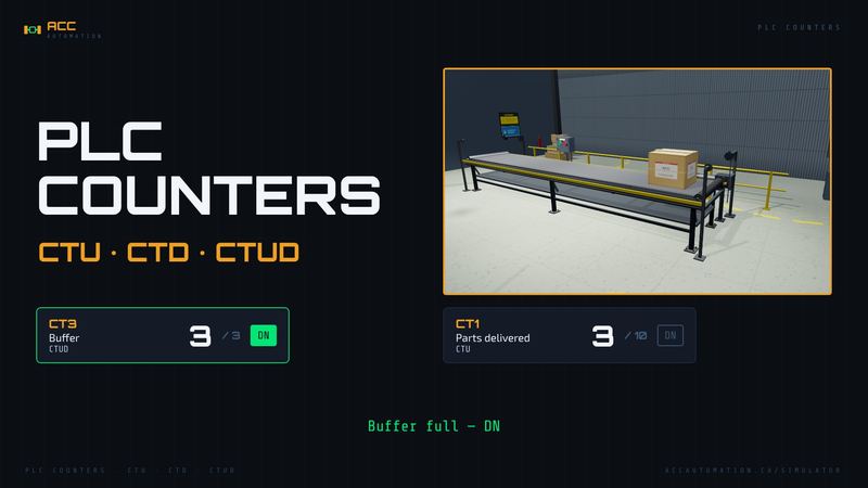
A sensor sees a box. The PLC counter adds one. That is the whole job, and it is still the instruction that produces some of the most confusing bugs on a plant floor: PLC counters that run away, counts that will not clear after a power cycle, and an up/down count whose done bit means “full” one minute and “empty” the next.
By the end of this post you will be able to use all three PLC counters: CTU to count up, CTD to count down, and CTUD to count both ways in one instruction. We will build them on the free ACC PLC Simulator with the 3D Conveyor scene: a conveyor delivers parts to a buffer, a counter tracks how many are waiting, and the conveyor holds when the buffer is full or the batch is done. Then we test every case, including the one that catches people out.
If you worked through the timer post, counters will feel familiar: same preset, same accumulator, same done bit. The difference is what makes them tick.
Watch it on YouTube:
CTU vs CTD vs CTUD: Which PLC Counter Do You Need?
Previously, we examined…
- Motor Starter Logic: Build a Fail-Safe System in 5 Rungs · Video
- TON, TOF, or RTO? Which PLC Timer Should You Use? · Video
- 17 to 42 Instructions in One Week: The Free PLC Simulator Just Leveled Up · Video
- Run Two 3D Machines at Once — Multi-Scene PLC Simulator · Video
- I Replaced a $5,000 PLC Trainer with Free PLC Training Simulator · Video
- Can AI Program a PLC? I Tested It Live in the ACC PLC Simulator · Video
- ACC PLC Simulator — How to Use Structured Text (ST) Programming · Video
- ACC PLC Simulator: Any Gamepad Now Drives Your PLC! · Video
- PLC Programming Tutorial: Build a Conveyor System (ACC Simulator) · Video
- Control 3D PLC Scenes With Zero Hardware? Here’s How · Video
- ACC PLC Simulator – How to Use the Free Browser-Based PLC Trainer · Video
- How to Use the ACC PLC Simulator — Control Panel Scene Tutorial · Video
The Four Ideas Behind Every PLC Counter
A counter counts edges, not time
A counter does not care how long its rung is true. It adds one on the rising edge: the single scan where the rung goes from false to true. A box can sit in front of a sensor for ten seconds and it still counts once. To count again, the rung has to go false and then true again.
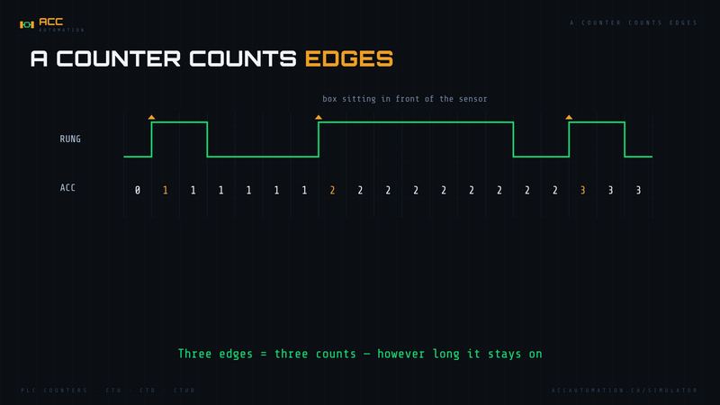
That is also why a pushbutton wired straight to a counter usually counts once per press, while a contact that chatters counts every bounce. The counter is doing exactly what it was told.
CTU — count up
Every counter in the simulator has three parts you can read in the program:
- PRE, the preset: the target count.
- ACC, the accumulator: the count so far, read as
CT1/ACC. - DN, the done bit: read as a contact on
CT1.
A CTU adds 1 to ACC on every rising edge of its rung. DN turns on when ACC reaches PRE. It does not stop there: the next edge makes it PRE + 1, then PRE + 2. Reaching the preset is a signal, not a limit.
CTD — count down
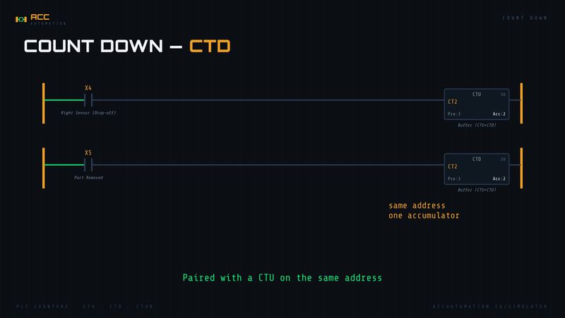
A CTD subtracts 1 from ACC on every rising edge of its rung and never goes below zero. Its DN bit turns on when the count reaches zero.
On its own, a ladder CTD has nothing to count down from, because ACC starts at zero. That is why it is almost always paired with a CTU on the same address: the CTU adds, the CTD takes away, and the two share one accumulator. Older PLCs built every up/down count this way. On an AutomationDirect Click the counter instruction can be set to count up, count down or both; in Studio 5000 you pair CTU and CTD on one COUNTER tag, exactly as we do with CT2 below.
In Structured Text the IEC CTD has a load input, so it can count down from the preset on its own. More on that in STEP 4.
CTUD — count up and down in one instruction
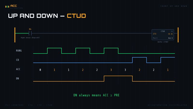
A CTUD counts up on the rising edge of its rung and down on the rising edge of a second bit, its CD input. It never goes below zero, and if both edges arrive on the same scan they cancel. Most importantly, its DN bit always means the same thing: ACC is at or above PRE.
Counters remember
Counters are retentive. Take the PLC to STOP and back to RUN and the count is still there, because on a real machine the parts did not disappear just because the program stopped. The only way to clear a counter is a RES instruction on its address, which sets ACC to zero and turns DN off.
Program Development – PLC Counters
STEP 1 — Define the Task
The Conveyor scene is a belt conveyor with a proximity sensor at each end and a box that rides on the belt. We will treat it as a shuttle: the left end is the load station, the right end is the drop-off, and every time the box reaches the drop-off it delivers one part into a buffer for the next machine. In plain English:
- Run. Start begins the conveyor and Stop ends it. The box travels to the drop-off, reverses, comes back to the load station, and goes again.
- Count deliveries. Every arrival at the drop-off is one part delivered. A batch is 10 parts.
- Track the buffer. Every delivery adds a part to the buffer. When the next machine takes a part out, the buffer goes down by one. The buffer holds 3 parts.
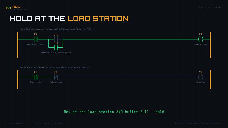
- Hold at the load station. If the buffer is full, or the batch of 10 is done, the conveyor waits at the load station instead of sending another part. It never stops halfway down the belt.
- Reset. A reset clears all the counts for a new batch.
Number 4 is a design choice worth copying. Stopping a conveyor with a part in the middle of the belt is how jams start; holding at the load station means the belt is always empty when it waits.
STEP 2 — Define the I/O
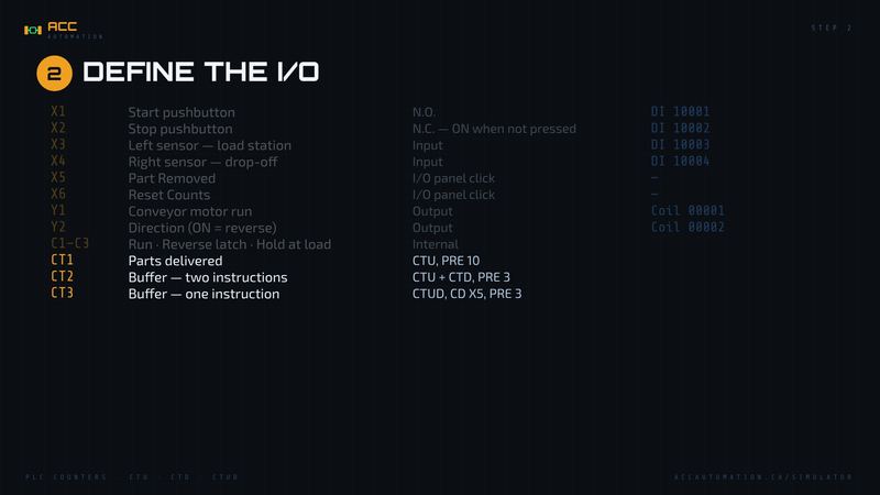
| Address | Description | Type | Modbus |
|---|---|---|---|
| X1 | Start pushbutton (N.O.) | Input | DI 10001 |
| X2 | Stop pushbutton (N.C. — ON when not pressed) | Input | DI 10002 |
| X3 | Left sensor — load station | Input | DI 10003 |
| X4 | Right sensor — drop-off | Input | DI 10004 |
| X5 | Part Removed — click in the simulator I/O panel | Input | — |
| X6 | Reset Counts — click in the simulator I/O panel | Input | — |
| Y1 | Conveyor motor run | Output | Coil 00001 |
| Y2 | Direction (ON = reverse, towards the load station) | Output | Coil 00002 |
| C1 | Conveyor run (seal-in) | Internal bit | — |
| C2 | Reverse latch | Internal bit | — |
| C3 | Hold at load | Internal bit | — |
| CT1 | Parts delivered — CTU, PRE 10 | Counter | — |
| CT2 | Buffer, two instructions — CTU + CTD, PRE 3 | Counter | — |
| CT3 | Buffer, one instruction — CTUD, CD = X5, PRE 3 | Counter | — |
The scene supplies X1 to X4. X5 and X6 are not part of the scene, so you click them yourself on the I/O tab of the simulator. On a real machine X5 would be a sensor on the next machine’s infeed and X6 a reset pushbutton. Click an input once to turn it on and again to turn it off; the counter sees the rising edge.
CT2 and CT3 count exactly the same thing on purpose. Running them side by side is the clearest way to see why CTUD exists.
On an AutomationDirect Click the drop-off sensor would land on input X004; on a CompactLogix you would create a tag such as DropOff_PE. The logic stays the same.
STEP 3 — Develop the Sequence
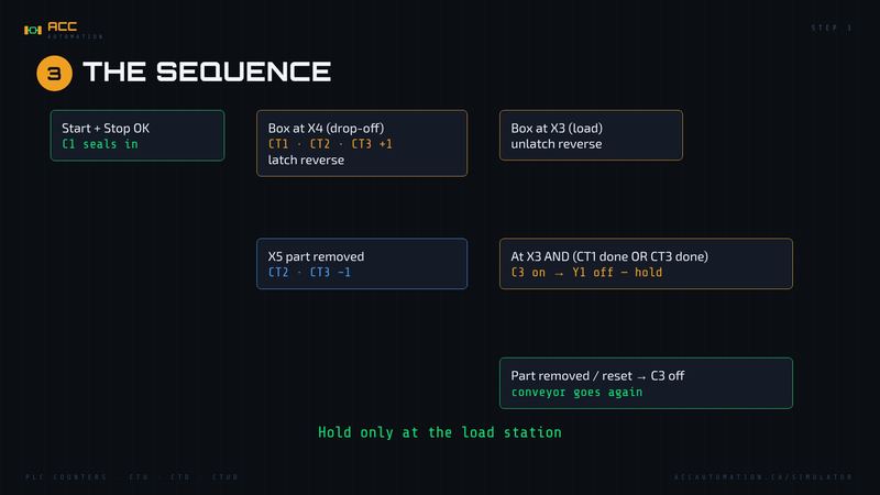
- Start (X1) with Stop (X2) ON sets C1, which seals itself in.
- With C1 on, the box reaching the drop-off (X4) latches reverse (C2). Back at the load station (X3) it unlatches, so the box shuttles back and forth.
- Each rising edge of X4 adds 1 to CT1 (parts delivered), CT2 (CTU half) and CT3 (CTUD).
- Each rising edge of X5 takes 1 off CT2 (CTD half) and CT3 (CTUD down input).
- When the box is at the load station (X3) and either CT1 is done (10 delivered) or CT3 is done (buffer at 3), C3 turns on and the motor Y1 stops.
- When a part is removed, CT3 drops below 3, C3 turns off and the conveyor goes again on its own. After a batch, X6 resets the counters.
Two questions to answer before you build it: what does CT2’s done bit show after you empty the buffer, and what happens to the counts when you press STOP and RUN again? (Answers in STEP 5.)
STEP 4 — Develop the PLC Program
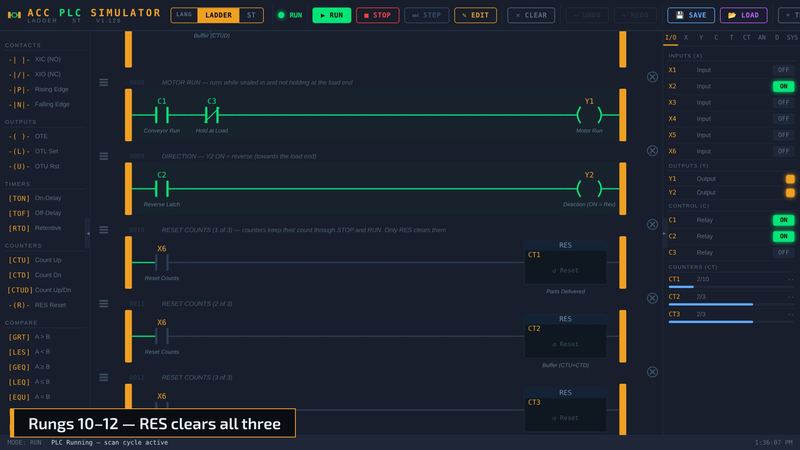
Thirteen rungs, every one commented. The first three are the conveyor from the Conveyor scene tutorial; everything after that is counting.
| Rung | Logic | Comment |
|---|---|---|
| 0 | ( X1 OR C1 ) AND X2 → C1 |
Conveyor run seal-in |
| 1 | C1 AND X4 → OTL C2 |
Reverse at the drop-off |
| 2 | C1 AND X3 → OTU C2 |
Forward again at the load station |
| 3 | X4 → CTU CT1, PRE 10 |
Parts delivered, batch of 10 |
| 4 | X4 → CTU CT2, PRE 3 |
Buffer, two instructions — count up |
| 5 | X5 → CTD CT2, PRE 3 |
Buffer, two instructions — count down, same address |
| 6 | X4 → CTUD CT3, CD X5, PRE 3 |
Buffer, one instruction |
| 7 | X3 AND ( CT1 OR CT3 ) → C3 |
Hold at load: batch done or buffer full |
| 8 | C1 AND NOT C3 → Y1 |
Motor runs unless holding |
| 9 | C2 → Y2 |
Direction |
| 10–12 | X6 → RES CT1 / CT2 / CT3 |
Reset counts |
To build it yourself, drag CTU from the COUNTERS section onto a rung after an XIC contact on X4 and double-click it to set CT1 and a preset of 10. For CTUD, the edit dialog has a CD field: type X5 there. RES is in the same section; give it the counter’s address.
Or skip the typing: download acc-example-conveyor-counters.json and import it with LOAD.
Three things to notice:
- The counters read the sensor directly. X4 is on for a fraction of a second as the box passes, then off as it reverses. One pass, one rising edge, one count. No one-shot is needed here because the sensor already gives a clean pulse. (When a signal stays on, or you need one scan out of a long press, that is the next post.)
- Rung 7 checks the load station first. CT3 turns on the moment the third part arrives at the drop-off, but the conveyor keeps going until the box is back at X3. That is the “never stop halfway” rule from STEP 1, in one contact.
- CT2 and CT3 count the same parts. Rungs 4 and 5 are how an up/down count was built before CTUD existed. Watch their done bits in STEP 5; they do not agree.
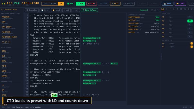
The Same Program in Structured Text
VAR
  ConveyorRun : BOOL;    // sealed-in run request
  Reverse     : BOOL;    // direction latch
  HoldAtLoad  : BOOL;    // do not send another part
  Delivered   : CTU;     // parts delivered, batch of 10
  Remaining   : CTD;     // parts left in the batch, counts down from 10
  Buffer      : CTUD;    // parts waiting in the buffer
END_VAR

ConveyorRun := (X1 OR ConveyorRun) AND X2;

IF ConveyorRun AND X4 THEN
  Reverse := TRUE;
END_IF;
IF ConveyorRun AND X3 THEN
  Reverse := FALSE;
END_IF;

Delivered(CU := X4, R := X6, PV := 10);
Remaining(CD := X4, LD := X6, PV := 10);
Buffer(CU := X4, CD := X5, R := X6, PV := 3);

HoldAtLoad := X3 AND (Delivered.Q OR Buffer.QU);

Y1 := ConveyorRun AND NOT HoldAtLoad;
Y2 := Reverse;
The IEC counters are function blocks with named inputs. CU counts up, CD counts down, R resets and PV is the preset. The current count is .CV.
Two differences from the ladder are worth knowing:
- CTUD has two done bits.
QUis on when the count is at or above the preset (full).QDis on when the count is zero (empty). No guessing which one you are looking at. - CTD can count down by itself. Its
LDinput copies the preset into the count, then each rising edge ofCDtakes one off, andQturns on at zero.Remainingstarts at 10 and counts down as parts are delivered. Click X6 once after you load the program so it has a count to start from.
Download the commented file: acc-example-conveyor-counters.st.
STEP 5 — Test the Program
- Open the ACC PLC Simulator and load the example program.
- Click CONNECT and launch the Conveyor System scene.
- Press RUN in the simulator, then press Start on the scene.
Keep the counter blocks in view (or the CT tab of the I/O panel) while you work through these tests:
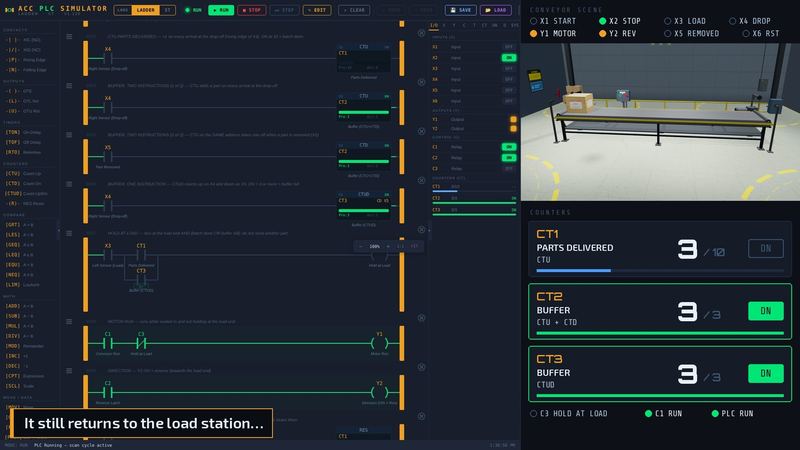
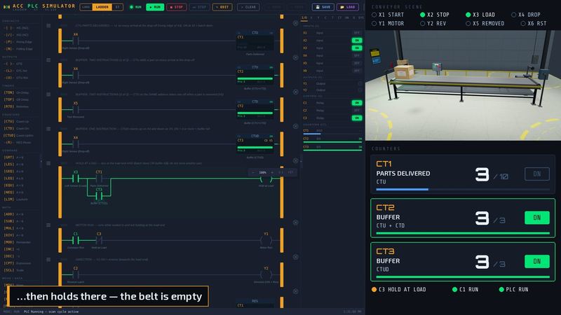
Test the count. Watch the box reach the right sensor. CT1, CT2 and CT3 all go from 0 to 1 on the same scan. The box reverses, returns to the left sensor and goes again. Each arrival adds exactly one, no matter how slowly the box passes.
Test buffer full. On the third delivery CT2 and CT3 both reach 3 and both done bits turn on. The box still returns to the load station, and only then does the motor stop. C3 is on, Y1 is off, and the belt is empty.
Test removing a part. On the I/O tab, click X5 on, then off. CT2 and CT3 drop to 2, CT3’s done bit goes off, C3 drops and the conveyor goes again by itself. The next delivery takes the buffer back to 3 and it holds again.
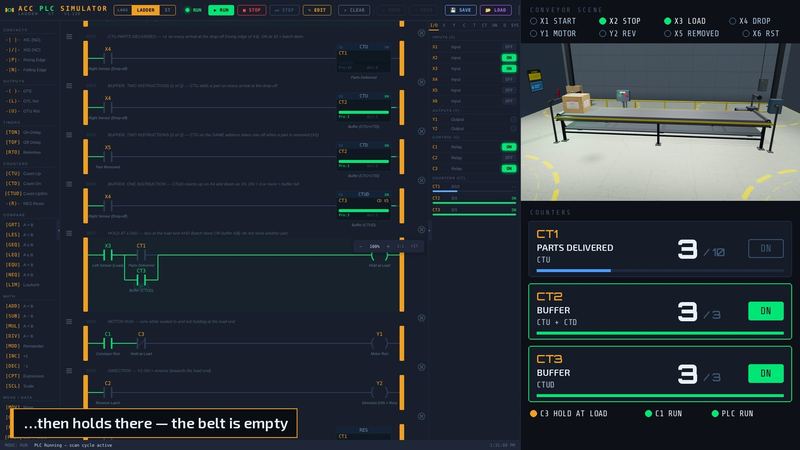
Test the two questions from STEP 3. Click X5 on and off until the buffer is empty. CT3 reads 0 with its done bit off. CT2 also reads 0, but its done bit is on. The CTD set it, because a CTD’s done bit means “reached zero”. So with a CTU and CTD pair, DN means full after the last count up and empty after the last count down. That is the bug. If you build an up/down count from a pair, compare the accumulator (CT2/ACC) instead of trusting DN, or use a CTUD and let DN mean one thing.
Now press STOP and RUN. The conveyor stops and needs Start again, because C1 is an ordinary internal bit. The counts are all still there. Counters are retentive.
Test the batch. Keep removing parts until CT1 reaches 10. The done bit on CT1 turns on and the conveyor holds at the load station even with room in the buffer. Click X6 on and off: all three counts go to zero, C3 drops and a new batch starts.
Testing with a Real PLC over Modbus
To run the same logic in your own PLC, start the bridge (node acc-modbus-bridge.js), click ⬡ MODBUS → CONNECT in the Conveyor scene, and point your PLC’s Modbus TCP client at the bridge:
| Setting | Value |
|---|---|
| IP address | Your PC’s LAN IP (127.0.0.1 for Modbus Poll on the same PC) |
| Port | 502 (or 5020 if you started the bridge with --modbus-port 5020) |
| Unit ID | 1 |
| Read inputs | FC02 Discrete Inputs 10001–10004 (X1–X4) |
| Write outputs | FC05 Coils 00001–00002 (Y1–Y2), or FC15 to write both at once |
The counters now live in your PLC, so Part Removed and Reset Counts become two of your PLC’s own inputs; wire a pushbutton to each or toggle them from your programming software. Poll the inputs fast enough to catch the sensors. The box passes each sensor in about 100 ms, so a 500 ms poll will miss counts. If your counts come up short, that is the first thing to check.
Three counters, one conveyor:
- CTU adds one on every rising edge. DN turns on at the preset, and counting carries on past it.
- CTD takes one away and stops at zero. In ladder it pairs with a CTU on the same address; in ST it can load its preset and count down on its own.
- CTUD counts both ways in one instruction, with a done bit that always means “at or above the preset”.
- Counters are retentive. STOP, RUN and power cycles keep the count. Only RES clears it.
When you build an up/down count, test the empty case as well as the full one. That is where a CTU and CTD pair gives you a done bit you did not expect.
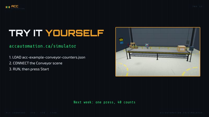
Next step: load the example into the ACC PLC Simulator, connect the Conveyor scene, then change the buffer preset to 5 on both CT2 and CT3 and see how the hold point moves. For more practice, acc-example-buffer-runtime.json is a scene-free version that adds LIM high/low limits and an RTO run-time total. Next Monday: why one button press can count 40 times, and the P and N edge contacts that fix it.
Related posts
- PLC Programming Tutorial: Build a Conveyor System (ACC Simulator)
- TON, TOF, or RTO? Which PLC Timer Should You Use?
- Motor Starter Logic: Build a Fail-Safe System in 5 Rungs
- ACC PLC Simulator — How to Use Structured Text (ST) Programming