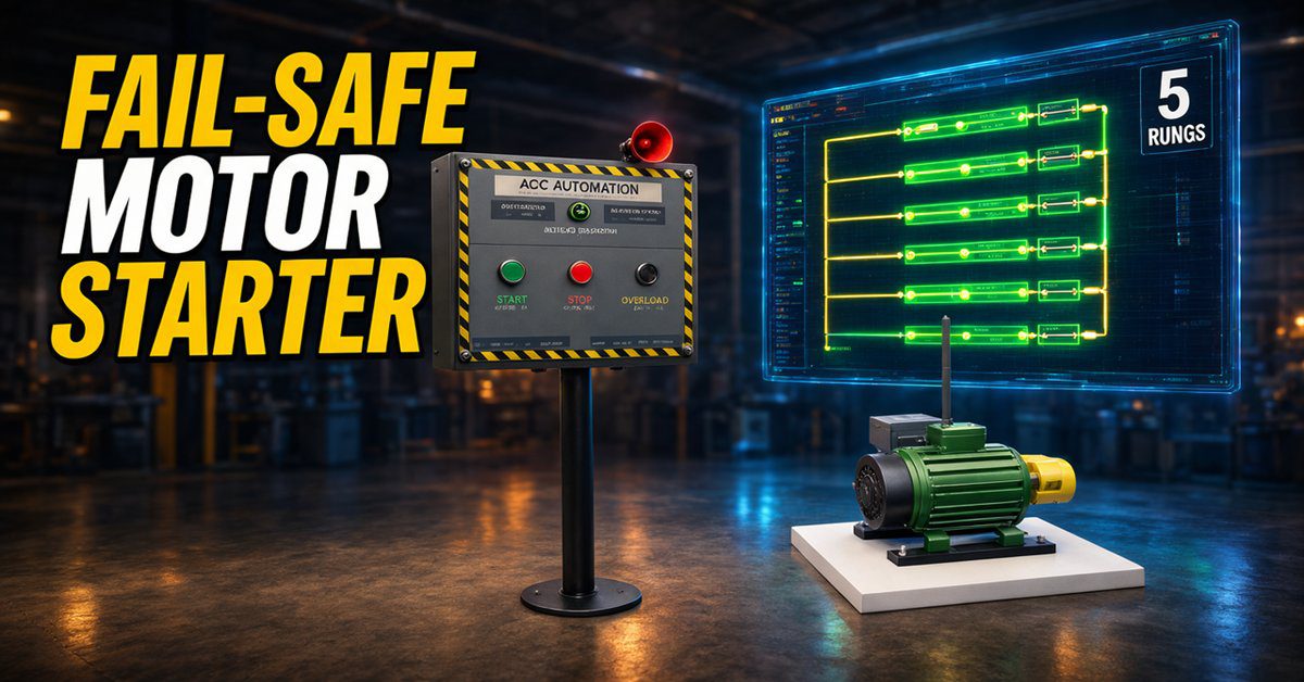
Start, stop, overload. Almost every motor in a plant is controlled by those three signals, and almost every PLC programmer writes the rung that ties them together in their first week. This is the motor starter ladder logic. It is also where a surprising number of real faults come from: a stop button examined with the wrong contact, a seal-in that survives an overload reset, a warning horn that a quick press can skip.
By the end of this post you will be able to write a complete motor starter program in five rungs: a seal-in start, a normally closed stop that fails safe, a motor overload contact that blocks restarts, and a 2-second warning horn that sounds before the contactor pulls in. You will build it in the free ACC PLC Simulator, connect the 3D Motor Starter scene, and test every case, including the ones that catch people out.
If you have just read the timer post, this is where the TON goes to work. If you have not, that is fine. The one timer we use is explained as we go.
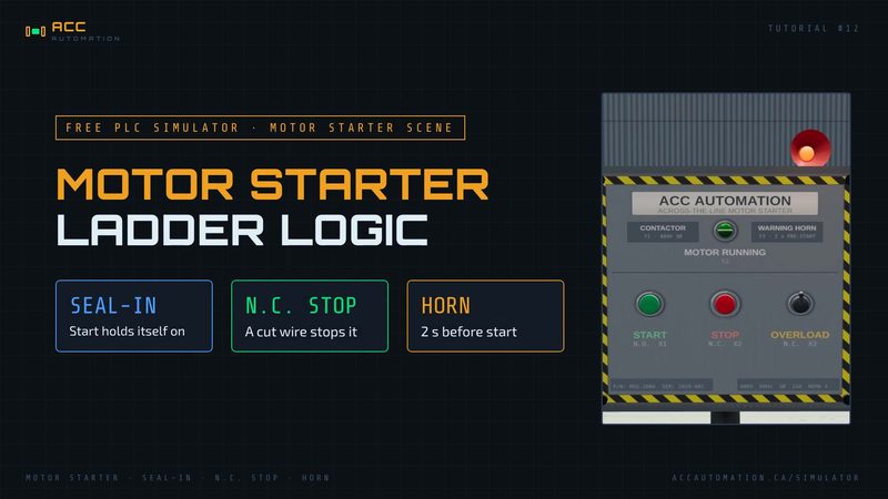
YouTube Video – Motor Starter Logic: Build a Fail-Safe System in 5 Rungs
Previously, we examined…
- TON, TOF, or RTO? Which PLC Timer Should You Use? · Video
- 17 to 42 Instructions in One Week: The Free PLC Simulator Just Leveled Up · Video
- Run Two 3D Machines at Once — Multi-Scene PLC Simulator · Video
- I Replaced a $5,000 PLC Trainer with Free PLC Training Simulator · Video
- Can AI Program a PLC? I Tested It Live in the ACC PLC Simulator · Video
- ACC PLC Simulator — How to Use Structured Text (ST) Programming · Video
- ACC PLC Simulator: Any Gamepad Now Drives Your PLC! · Video
- PLC Programming Tutorial: Build a Conveyor System (ACC Simulator) · Video
- Control 3D PLC Scenes With Zero Hardware? Here’s How · Video
- ACC PLC Simulator – How to Use the Free Browser-Based PLC Trainer · Video
- How to Use the ACC PLC Simulator — Control Panel Scene Tutorial · Video
The Four Ideas Behind Every Motor Starter
The across-the-line starter
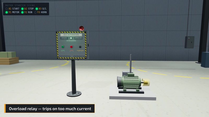
An across-the-line (or direct-on-line) starter connects the motor straight to the supply. It has two parts: a contactor, a heavy-duty relay whose coil the PLC turns on, and an overload relay, which watches motor current and trips if the motor draws too much for too long. The overload relay has a small auxiliary contact that tells the PLC it has tripped. On the Motor Starter scene the contactor is Y1 and the overload auxiliary contact is X3.
The seal-in
A Start pushbutton is momentary. It is on for the half second your finger is on it, then it springs back. If the motor only ran while X1 was on, you would have to hold the button all day. A seal-in (also called a latch or holding circuit) fixes that: the output’s own contact is wired in parallel with Start, so once the rung is true it holds itself true after the button is released. The only way out is to break something in series with it, which is exactly what Stop and the overload do.
The normally closed stop
The Stop button on this scene is wired normally closed (N.C.). Current flows through it all the time, so X2 is ON while nobody is touching it and goes OFF when it is pressed.
That looks backwards until you think about what fails. If the Stop wire is cut, or a terminal works loose, an N.O. stop button would read exactly the same as “not pressed” and the motor would keep running with no way to stop it. An N.C. stop reads a broken wire the same as a pressed button, so the failure stops the motor. The overload contact X3 is wired N.C. for the same reason.
This is the part that trips people up in the program. Because X2 is ON in the normal condition, you examine it with a normally open contact (XIC). The rule is: read the state, not the label. The symbol in the ladder asks “is this bit ON?”, and for an N.C. device, ON means healthy.
The pre-start warning
On many machines a motor must not start without warning. People work close to conveyors, mixers and fans, so the control sounds a horn first to clear the area, then starts the motor. On the Motor Starter scene the horn is Y3 and the warning period is 2 seconds. That warning is a TON on-delay timer: it times while its rung is true and turns its done bit on when the preset is reached.
STEP 1 — Define the Task
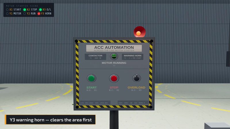
The Motor Starter scene is a floor-mounted NEMA 4 control station driving an across-the-line starter: a green Start button, a red Stop button, an overload reset selector, a green run light and a roof-mounted warning horn. In plain English:
- Start. Pressing Start begins a start sequence. The warning horn sounds for 2 seconds, then the motor contactor pulls in and the green run light comes on.
- Stop. Pressing Stop drops everything immediately, at any point, including during the warning.
- Overload. If the overload trips, everything drops and the motor cannot be restarted until the overload is reset.
- No automatic restart. The motor never restarts on its own: not after a stop, not after an overload reset, and not when power comes back.
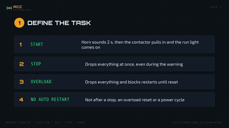
Number 4 separates a real starter circuit from a textbook latch. It’s why the seal-in exists at all.
STEP 2 — Define the I/O
| Address | Description | Type | Modbus |
|---|---|---|---|
| X1 | Start pushbutton (N.O. — ON while pressed) | Input | DI 10001 |
| X2 | Stop pushbutton (N.C. — ON when not pressed) | Input | DI 10002 |
| X3 | Motor overload aux contact (N.C. — ON while healthy, maintained) | Input | DI 10003 |
| Y1 | Motor contactor | Output | Coil 00001 |
| Y2 | Run light (green) | Output | Coil 00002 |
| Y3 | Warning horn | Output | Coil 00003 |
| C1 | Start request (internal) | Internal bit | — |
| T1 | Warning timer — TON, 2000 ms | Timer | — |
The overload contact is maintained: when it trips, it stays tripped until somebody resets it, exactly like a real overload relay. That is why the scene gives it a TRIP/RESET selector instead of a pushbutton.
On an AutomationDirect, clicking the Start button would land on input X001; on a CompactLogix, you would create a tag such as Start_PB. The logic stays the same.
STEP 3 — Develop the Sequence
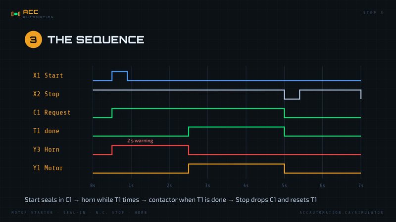
- Start (X1), with Stop (X2) and the overload (X3) both ON, sets the start request C1, which seals itself in.
- C1 drives the TON T1 with a 2-second preset.
- While C1 is on and T1 is not yet done, the horn Y3 sounds and the contactor stays off.
- When T1 is done, the horn stops and the contactor Y1 pulls in.
- The run light Y2 follows Y1.
- Losing X2 or X3 drops C1. That resets T1 at once, so everything downstream drops too.
Why seal in on C1 and not on Y1, the way a hardwired starter seals on the contactor’s auxiliary contact? Because the contactor does not pull in for 2 seconds. Start has long been released by then. The request has to hold itself through the warning period, so it gets its own internal bit.
Two questions to answer before you build it: what happens if Start is held down, and what happens if Start is pressed again while the motor is running? (Answers in STEP 5.)
STEP 4 — Develop the PLC Program (Motor Starter Ladder Logic)
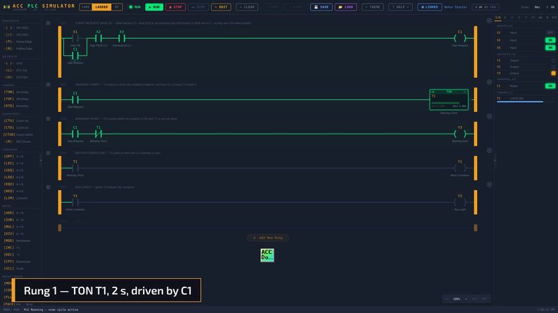
Five rungs, each one commented.
| Rung | Logic | Comment |
|---|---|---|
| 0 | ( X1 OR C1 ) AND X2 AND X3 → C1 |
Start request seal-in — Stop or an overload trip breaks it |
| 1 | C1 → TON T1, PRE 2000 ms |
Warning timer, timed from the sealed-in request |
| 2 | C1 AND NOT T1 → Y3 |
Warning horn during the warning only |
| 3 | T1 → Y1 |
Contactor pulls in when the warning is over |
| 4 | Y1 → Y2 |
Run light follows the contactor |
To build it yourself, drag an XIC contact onto rung 0 for X1, add a parallel branch with C1 underneath it, then add XIC contacts for X2 and X3 and an OTE coil for C1. Drag TON from the TIMERS section for rung 1 and double-click it to set T1 and 2000 ms. Rung 2 uses an XIO (normally closed) contact on T1.
Or skip the typing: download acc-example-motor-starter.json and import it with LOAD.
Three things to notice:
- X2 and X3 are XIC contacts. Both devices are N.C., so both bits are ON when the machine is healthy. An XIO on X2 is the classic mistake: rung 0 could only go true while somebody held Stop down, so Start would do nothing on its own, and the one way to start the motor would be to press Start and Stop together.
- The timer is driven by C1, not by X1. A press of the Start button lasts a fraction of a second. If X1 drove the TON, it would reset the moment you let go, and the motor would never start.
- Rung 2 uses XIO on T1. The horn is “request on AND warning not finished”. When T1 finishes, the horn stops on the same scan that the contactor pulls in, so there is no gap and no overlap.
The Same Program in Structured Text
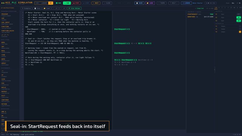
VAR
  StartRequest : BOOL;   // sealed-in start request
  WarnTimer    : TON;    // 2 s warning before the contactor pulls in
END_VAR

StartRequest := (X1 OR StartRequest) AND X2 AND X3;

WarnTimer(IN := StartRequest, PT := T#2s);

Y3 := StartRequest AND NOT WarnTimer.Q;
Y1 := WarnTimer.Q;
Y2 := Y1;
The seal-in is one line: the request feeds back into its own expression, exactly like the parallel C1 branch in the ladder. X2 and X3 appear as plain AND X2 AND X3, not AND NOT, for the same reason they are XIC contacts. Download the commented file: acc-example-motor-starter.st.
A Note on Real Stop Circuits
A PLC Stop input is a control stop. An emergency stop is a different circuit: on a real machine it removes power through hardwired, safety-rated devices and does not depend on the PLC scanning correctly. The normally closed wiring in this lesson is the same fail-safe idea, but it is not a substitute for an E-stop designed to your local safety standards.
STEP 5 — Test the Program
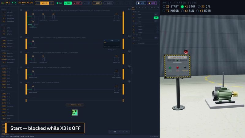
- Open the ACC PLC Simulator and load the example program.
- Click CONNECT and launch the Motor Starter scene.
- Press RUN in the simulator.
Watch the I/O panel and rung 1 while you work through these tests:
Test the start. Press Start and let go. C1 seals in, the horn sounds, and its strobe flashes while T1 counts to 2.00 s. Then the horn stops, the contactor pulls in, the motor turns, and the green run light comes on.
Test the stop. With the motor running, press Stop. Y1 and Y2 drop on the next scan. C1 drops with them, so letting go of Stop does nothing.
Test a stop during the warning. Press Start, then press Stop about one second in, while the horn is still sounding. The horn stops, and the motor never starts. T1 went back to zero when C1 dropped, so the start was aborted, not postponed.
Test the overload. Start the motor and click TRIP on the overload. Everything drops. Press Start: nothing happens, because X3 is OFF and rung 0 cannot go true. Click RESET. The motor stays stopped. It only starts again when somebody presses Start, and the horn sounds first.
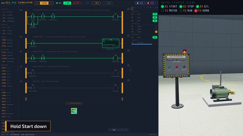
Test the two questions from STEP 3. Hold Start down: the horn still sounds for the full 2 seconds, then the motor starts. Holding Start cannot skip or shorten the warning, because T1 is timed from C1. Press Start while the motor is running: nothing changes, because C1 is already sealed in.
Testing with a Real PLC over Modbus
To run the same logic in your own PLC, start the bridge (node acc-modbus-bridge.js), click ⬡ MODBUS → CONNECT in the Motor Starter scene, and point your PLC’s Modbus TCP client at the bridge:
| Setting | Value |
|---|---|
| IP address | Your PC’s LAN IP (127.0.0.1 for Modbus Poll on the same PC) |
| Port | 502 (or 5020 if you started the bridge with --modbus-port 5020) |
| Unit ID | 1 |
| Read inputs | FC02 Discrete Inputs 10001–10003 (X1–X3) |
| Write outputs | FC05 Coils 00001–00003 (Y1–Y3), or FC15 to write all three at once |
At rest you should read DI 10001 = 0, DI 10002 = 1 and DI 10003 = 1. If Stop or the overload reads 0 with nobody touching anything, your PLC program will refuse to start, which is exactly what the N.C. wiring is for. The timer now runs in your PLC; the scene supplies the buttons and the overload and shows the horn, contactor and light.
Five rungs cover the whole motor starter:
- Seal-in — a momentary Start holds itself on through an internal bit.
- N.C. stop and overload — both are ON when healthy, both are examined with XIC, and a broken wire stops the motor.
- Warning horn — a TON timed from the sealed-in request, with the horn on while the timer is not done.
- No automatic restart — because the request has to be sealed in again, a stop, an overload reset or a power cycle always needs a fresh press of Start.
Test the stop during the warning and the overload reset every time you write one of these. Those two cases are where real starter programs go wrong.
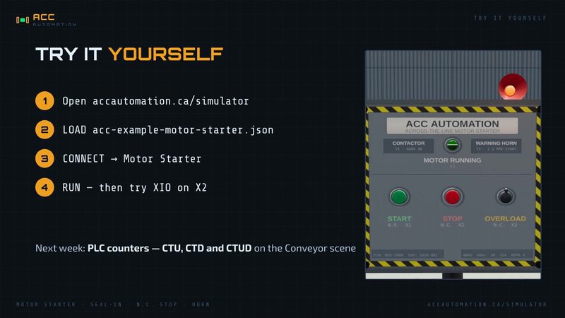
Next step: load the example into the ACC PLC Simulator, connect the Motor Starter scene, then change rung 0 to use XIO on X2 and see what Start and Stop do now. Next Monday, we count parts in and out of a buffer on the Conveyor scene with CTU, CTD, and CTUD counters.
Related posts
- TON, TOF, or RTO? Which PLC Timer Should You Use?
- How to Use the ACC PLC Simulator — Control Panel Scene Tutorial
- ACC PLC Simulator — How to Use Structured Text (ST) Programming
- Control 3D PLC Scenes With Zero Hardware? Here’s How