
Rising Edge / One-Shot in Ladder Logic (P and N Contacts)
Press a button once, and the count goes up by 40. Nothing is wrong with the button, the wiring or the PLC. The program did exactly what it was told, forty times in a row, because the PLC scanned the rung forty times while your finger was on the button. We will look at the rising edge ladder logic and ST programming.
By the end of this post, you will know why that happens and how to fix it with rising edge ladder logic and the two edge contacts: the rising edge (P) contact, which passes power for one scan when its bit turns on, and the falling edge (N) contact, which does the same when it turns off. We will build them on the free ACC PLC Simulator with the 3D Control Panel scene: a press counter done the wrong way and the right way side by side, a push-on/push-off motor from a single button, and a press counter on a normally closed Stop button, which is where most people get the edge backwards.
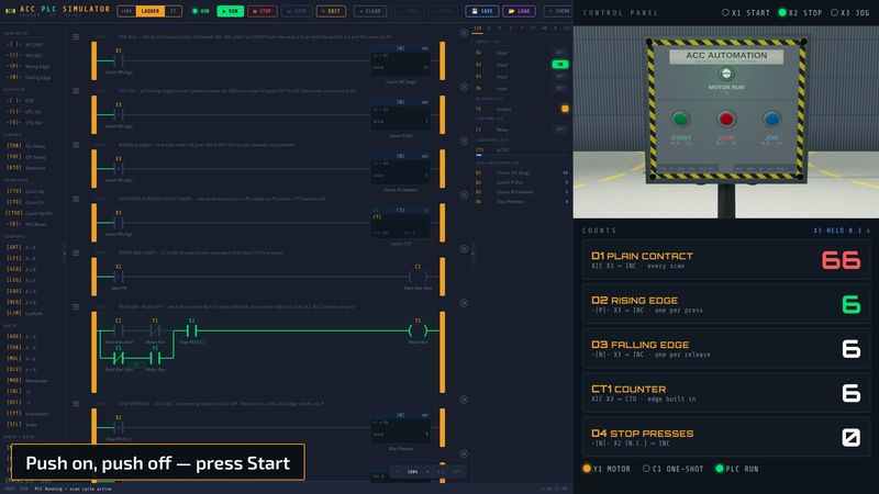
Last week’s counters never needed any of this. By the end, you will know why.
Watch this on YouTube:
Everything You Need to Know About One-Shot Instructions
Previously, we examined…
- CTU vs CTD vs CTUD: Which PLC Counter Do You Need? · Video
- Motor Starter Logic: Build a Fail-Safe System in 5 Rungs · Video
- TON, TOF, or RTO? Which PLC Timer Should You Use? · Video
- 17 to 42 Instructions in One Week: The Free PLC Simulator Just Leveled Up · Video
- Run Two 3D Machines at Once — Multi-Scene PLC Simulator · Video
- I Replaced a $5,000 PLC Trainer with Free PLC Training Simulator · Video
- Can AI Program a PLC? I Tested It Live in the ACC PLC Simulator · Video
- ACC PLC Simulator — How to Use Structured Text (ST) Programming · Video
- ACC PLC Simulator: Any Gamepad Now Drives Your PLC! · Video
- PLC Programming Tutorial: Build a Conveyor System (ACC Simulator) · Video
- Control 3D PLC Scenes With Zero Hardware? Here’s How · Video
- ACC PLC Simulator – How to Use the Free Browser-Based PLC Trainer · Video
- How to Use the ACC PLC Simulator — Control Panel Scene Tutorial · Video
Why One Press Counts 40 Times
The scan
A PLC does not wait for a button press. It runs in a loop: read every input, solve every rung from top to bottom, write every output, then start again. The ACC PLC Simulator scans every 100 ms. A real PLC is usually faster, often a few milliseconds a scan, which only makes the problem worse.
Now put a plain normally open contact (XIC) on a count button and drive an INC (add one) instruction with it. INC runs on every scan its rung is true. Hold the button for 4 seconds at a 100 ms scan and the rung is true for 40 scans. The register goes up by 40.
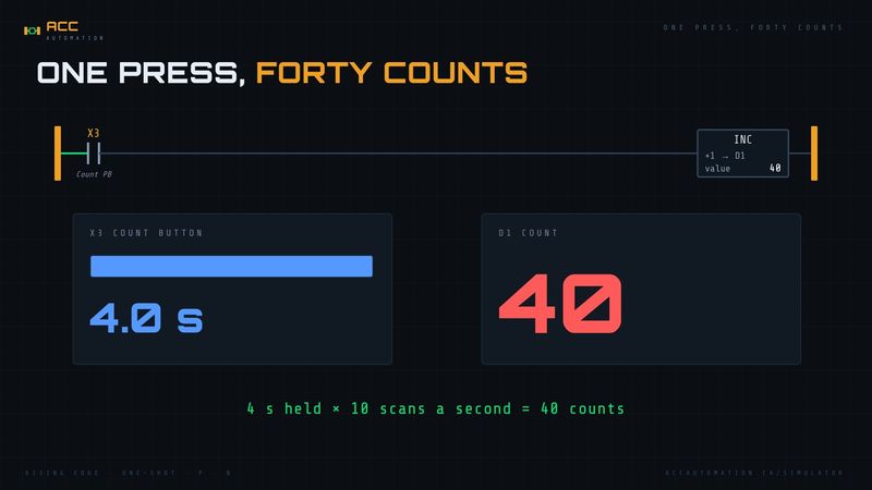
The same thing happens to every instruction that acts while its rung is true: ADD, SUB, MOV, a bit shift, a toggle. Any time you want something to happen once per event, not once per scan, you need an edge.
The rising edge (P) contact
A P contact watches its bit and passes power for exactly one scan: the scan where the bit goes from OFF to ON. On every other scan it is open, no matter how long the bit stays on. To fire again, the bit has to go OFF and then ON again.
That one-scan pulse is called a one-shot. Put a P contact in front of the INC and one press is one count.
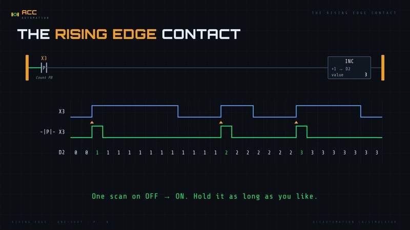
The falling edge (N) contact
An N contact is the mirror image: one scan when its bit goes from ON to OFF. Use it when the moment that matters is the release: a part leaving a sensor, a button being let go, a motor dropping out.
Why counters did not need one
In the counters post a CTU counted boxes straight off a sensor with no P contact. That works because a counter has edge detection built in: it adds one on the false-to-true change of its rung. Timers, math, move and bit-logic instructions do not. They act on every scan their rung is true.
What other PLCs call it
The idea is universal; the name changes. On an AutomationDirect Click these are the edge contacts (the up and down arrow contacts). In Studio 5000 the instructions are ONS, OSR and OSF, and each one needs its own storage bit. Siemens TIA Portal uses P and N contacts with an edge memory bit. In IEC 61131-3 Structured Text they are the R_TRIG and F_TRIG function blocks. The ACC PLC Simulator keeps the edge memory inside each P and N contact for you, so there is no storage bit to manage.
STEP 1 — Define the Task
The Control Panel scene is a floor-mounted panel with Start, Stop and Jog pushbuttons and a motor run pilot light. We will use it to build four small jobs, in plain English:
- Count presses, the wrong way and the right way. The Jog button becomes a Count button. Count its presses in one register with a plain contact, and in a second register with a P contact, so you can see the difference live.
- Count releases. Count the same button’s releases in a third register with an N contact, and count it once more with a CTU to prove counters already count edges.
- Push on, push off. The Start button turns the motor on with one press and off with the next. Stop always turns it off.
- Count Stop presses. Count every press of the Stop button, which is wired normally closed.
- Reset. One input clears every count.
Number 3 is a design you will use for years: one button for a light, a conveyor jog mode, a hand/auto select. Number 4 is the one that catches people out.
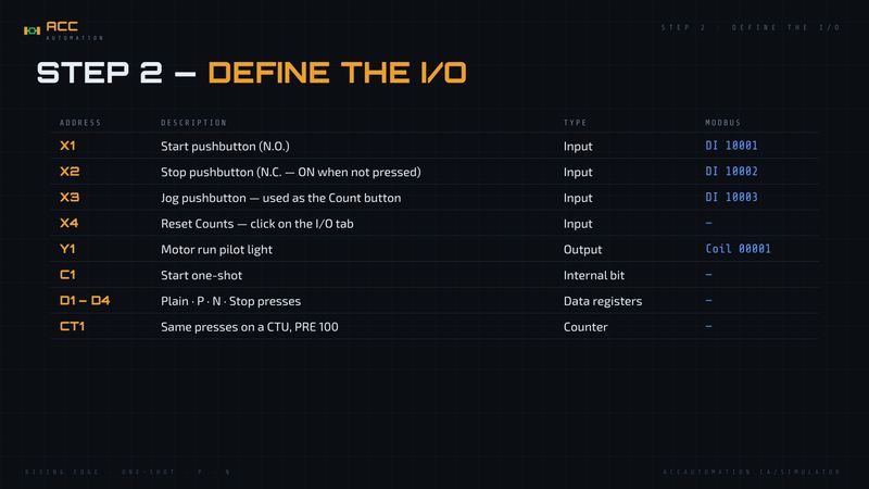
STEP 2 — Define the I/O
| Address | Description | Type | Modbus |
|---|---|---|---|
| X1 | Start pushbutton (N.O.) | Input | DI 10001 |
| X2 | Stop pushbutton (N.C. — ON when not pressed) | Input | DI 10002 |
| X3 | Jog pushbutton (N.O.), used here as the Count button | Input | DI 10003 |
| X4 | Reset Counts — click on the simulator I/O tab | Input | — |
| Y1 | Motor run pilot light | Output | Coil 00001 |
| C1 | Start one-shot | Internal bit | — |
| D1 | Presses counted with a plain contact (the bug) | Data register (INT) | — |
| D2 | Presses counted with a P contact (the fix) | Data register (INT) | — |
| D3 | Releases counted with an N contact | Data register (INT) | — |
| D4 | Stop presses | Data register (INT) | — |
| CT1 | The same presses on a CTU, PRE 100 | Counter | — |
The scene supplies X1 to X3 and shows Y1. X4 is not part of the scene, so you click it yourself on the I/O tab of the simulator. On a real machine it would be a reset pushbutton or an HMI button.
STEP 3 — Develop the Sequence
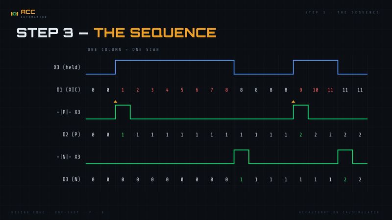
Draw the Count button (X3) on a timing chart, one column per scan, and the whole post is in the picture:
- While X3 is held, a plain XIC contact on X3 is true on every scan, so D1 goes up once per scan.
- A P contact on X3 is true for one scan, the first scan X3 is on, so D2 goes up by one per press.
- An N contact on X3 is true for one scan, the first scan X3 is off again, so D3 goes up by one per release.
- A CTU on X3 counts the same as D2.
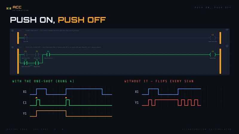
- Each press of Start (X1) makes a one-scan pulse on C1, and each pulse flips Y1. Stop (X2) turns Y1 off.
- Pressing Stop turns X2 off (it is normally closed), so the press is a falling edge and D4 counts on an N contact.
- X4 clears D1 to D4 and CT1.
Two questions before you build it: if the one-shot were removed from the Start toggle, what would the motor light do while you held Start? And if D4 used a P contact, when would it count? (Answers in STEP 5.)
STEP 4 — Develop the PLC Program
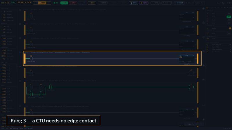
Nine rungs, every one commented.
| Rung | Logic | Comment |
|---|---|---|
| 0 | X3 → INC D1 |
The bug: adds 1 on every scan the button is held |
| 1 | P X3 → INC D2 |
The fix: one count per press |
| 2 | N X3 → INC D3 |
One count per release |
| 3 | X3 → CTU CT1, PRE 100 |
Counters already count edges |
| 4 | P X1 → C1 |
Start one-shot |
| 5 | ( C1 AND NOT Y1 ) OR ( NOT C1 AND Y1 ), AND X2 → Y1 |
Push on / push off; Stop always drops it |
| 6 | N X2 → INC D4 |
Stop presses (N.C. button: the press is the falling edge) |
| 7 | X4 → FLL 0 → D1, 4 values |
Reset counts |
| 8 | X4 → RES CT1 |
Reset the counter |
To build it yourself, drag Rising Edge (-|P|-) from the CONTACTS section onto a rung and give it the address X3, then drag INC (+1) from the MATH section after it and set the destination to D2. Falling Edge (-|N|-) is right below it. You can also change an existing contact: double-click it and pick P — Rising Edge Contact (one scan) from the type list. The Add Rung picker has two ready-made templates for this post: P → INC and P → Toggle.
Or skip the typing: download acc-example-one-shot.json and import it with LOAD.
Three things to notice:
- Rungs 0 and 1 differ by one letter. Same button, same instruction. The P is the whole fix.
- Rung 5 is the classic toggle. Read it as two cases. Pulse and the motor is off: turn it on. No pulse and the motor is on: keep it on. On the scan with the pulse and the motor already on, neither branch is true, so it turns off. Without the one-shot from rung 4, that flip would happen on every scan you held Start, and the light would land wherever it happened to be when you let go.
- Rung 6 uses N on purpose. X2 is normally closed: ON when nobody is touching it. A press turns it OFF. That OFF-going change is the falling edge.
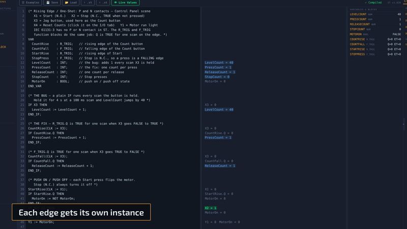
The Same Program in Structured Text
VAR
  CountRise    : R_TRIG;   // rising edge of the Count button
  CountFall    : F_TRIG;   // falling edge of the Count button
  StartRise    : R_TRIG;   // rising edge of Start
  StopPress    : F_TRIG;   // Stop is N.C., so a press is a FALLING edge
  LevelCount   : INT;      // the bug: adds 1 every scan X3 is held
  PressCount   : INT;      // the fix: one count per press
  ReleaseCount : INT;      // one count per release
  StopCount    : INT;      // Stop presses
  MotorOn      : BOOL;     // push on / push off state
END_VAR

IF X3 THEN                              // the bug
  LevelCount := LevelCount + 1;
END_IF;

CountRise(CLK := X3);                   // the fix
IF CountRise.Q THEN
  PressCount := PressCount + 1;
END_IF;

CountFall(CLK := X3);
IF CountFall.Q THEN
  ReleaseCount := ReleaseCount + 1;
END_IF;

StartRise(CLK := X1);                   // push on / push off
IF StartRise.Q THEN
  MotorOn := NOT MotorOn;
END_IF;
IF NOT X2 THEN
  MotorOn := FALSE;
END_IF;
Y1 := MotorOn;

StopPress(CLK := X2);                   // N.C. Stop: press = falling edge
IF StopPress.Q THEN
  StopCount := StopCount + 1;
END_IF;

IF X4 THEN                              // reset counts
  LevelCount := 0;  PressCount := 0;
  ReleaseCount := 0;  StopCount := 0;
END_IF;
Structured Text has no edge contacts. R_TRIG sets Q true for one scan when CLK goes FALSE to TRUE; F_TRIG does the same on TRUE to FALSE. Each instance remembers its own last value, so every edge you detect needs its own instance: CountRise and StartRise cannot be shared.
The toggle reads better in ST: MotorOn := NOT MotorOn inside the one-shot. Take the IF StartRise.Q away and the same line flips the motor on every scan.
Download the commented file: acc-example-one-shot.st.
STEP 5 — Test the Program
- Open the ACC PLC Simulator and load the example program.
- Click CONNECT and launch the Control Panel scene.
- Press RUN in the simulator.
Keep the D tab of the I/O panel (or the INC blocks) in view while you work through these tests:
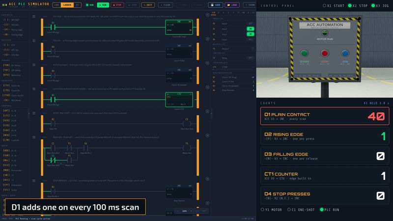
Test the press. Press and hold Jog for about four seconds. D1 climbs the whole time, roughly 10 a second, and stops at about 40 when you let go. D2 goes up by exactly one, on the scan you pressed. CT1 goes up by one too. That is the bug and the fix on the same button. (If you see 41, that is the simulator being helpful: it runs one extra scan the instant a scene input changes, so a quick tap can never slip between two 100 ms scans.)
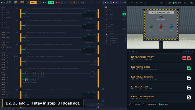
Test the release. Watch D3 as you let go of Jog. It goes up by one on release, not on press. Tap Jog a few times: D2, D3 and CT1 stay in step, one per tap. D1 adds a few each time, depending on how long your finger stays down.
Test push on, push off. Press Start: the motor light comes on. Press it again: off. Now hold Start down for a few seconds. Nothing else happens. That answers the first question from STEP 3: without the one-shot the toggle runs every scan, so the light flickers at the scan rate while you hold Start and stops in whatever state the last scan left it. Try it: double-click the P contact in rung 4, change it to XIC and hold Start.
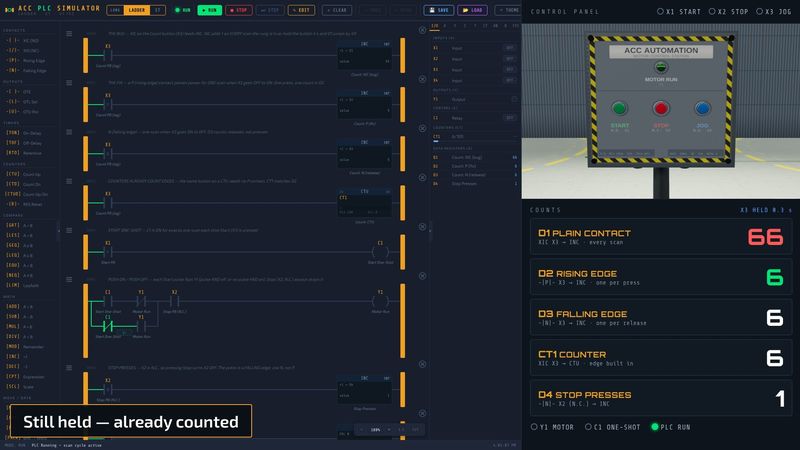
Test Stop. Turn the motor on and press Stop. The light goes off and D4 goes up by one as Stop goes down, not when it comes back up. That answers the second question: with a P contact on X2, D4 would count on the release, because the N.C. contact closes again when you let go.
Test reset. On the I/O tab, click X4 on, then off. D1 to D4 and CT1 go back to zero.
Testing with a Real PLC over Modbus
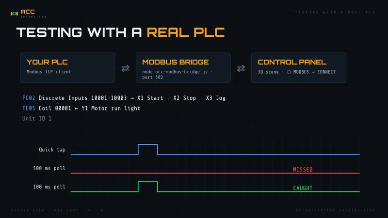
To run the same logic in your own PLC, start the bridge (node acc-modbus-bridge.js), click ⬡ MODBUS → CONNECT in the Control Panel scene, and point your PLC’s Modbus TCP client at the bridge:
| Setting | Value |
|---|---|
| IP address | Your PC’s LAN IP (127.0.0.1 for Modbus Poll on the same PC) |
| Port | 502 (or 5020 if you started the bridge with --modbus-port 5020) |
| Unit ID | 1 |
| Read inputs | FC02 Discrete Inputs 10001–10003 (X1–X3) |
| Write outputs | FC05 Coil 00001 (Y1) |
The edge contacts now live in your PLC, and they can only see what your Modbus poll sees. A quick tap on a pushbutton can be 100 ms or less. If your PLC polls the bridge every 500 ms, a tap can come and go between two polls and the PLC never sees it. Poll at 100 ms or faster. If presses go missing, that is the first thing to check. Reset Counts becomes one of your PLC’s own inputs or an HMI button.
Common One-Shot Mistakes
- Counting with a plain contact. Rung 0. If an instruction runs every scan its rung is true, it needs an edge in front of it to happen once per event.
- Using P on a normally closed device. A press of an N.C. Stop, or a part arriving at an N.C. sensor, turns the input OFF. That is a falling edge.
- Sharing edge memory. On PLCs where you give each one-shot a storage or edge memory bit, two one-shots on the same bit interfere and miss edges. Every one-shot needs its own. (The simulator stores it inside each contact; in ST, give each edge its own R_TRIG or F_TRIG.)
- Putting conditions in front of an edge contact. In the simulator the P and N contacts watch their bit, not the rung. If X3 turns on while an earlier contact on the rung is false, that edge is used up. When the condition goes true later, the P contact will not fire until X3 is pressed again. If you want “the moment both are true”, build the condition into a C bit first and put the P contact on that bit. (Studio 5000’s ONS works the other way: it one-shots whatever rung logic sits in front of it. Know which kind your PLC has.)
Rising Edge Ladder Logic
One press, one count:
- INC, ADD, MOV, toggles and shifts act on every scan their rung is true. A held button is many scans.
- A P contact passes power for one scan when its bit turns ON. An N contact does the same when it turns OFF.
- Counters already count edges, which is why last week’s CTU needed no P contact.
- On a normally closed button, the press is the falling edge.
- In Structured Text, R_TRIG and F_TRIG do the same job, one instance per edge.
Next step: load the example into the ACC PLC Simulator, connect the Control Panel scene, then change rung 0 to a P contact and watch D1 match D2. For a second practice, build a two-button version of the toggle with OTL and OTU and compare it with rung 5. Next Monday: PLC system bits, first scan and clock pulses, and how to blink a light with zero timers.
Related posts
- PLC Counters: CTU, CTD and CTUD Up/Down Counter
- How to Use the ACC PLC Simulator — Control Panel Scene Tutorial
- Motor Starter Logic: Build a Fail-Safe System in 5 Rungs
- ACC PLC Simulator — How to Use Structured Text (ST) Programming