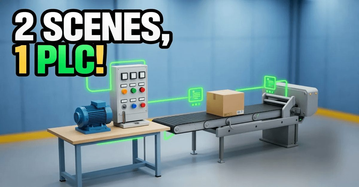
Until now, the ACC PLC Simulator ran one 3D scene at a time. You could program a motor starter, a conveyor, or a tank—but only one at a time— and the moment you connected a second scene, it fought the first for the same inputs. From version 1.121, that limit is gone. The multi-scene PLC simulator lets you connect several machines to one program at the same time, and it hands each machine its own block of PLC memory so they cannot collide.
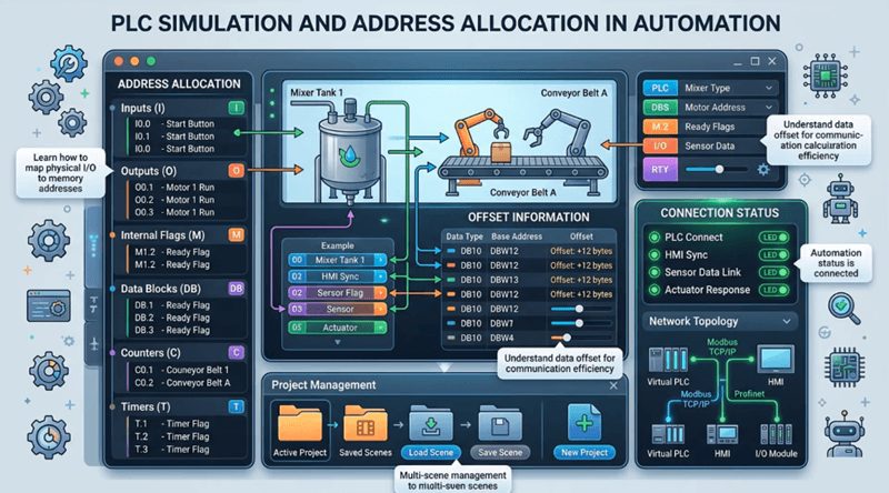
That last part is the whole feature. Letting two scenes talk to the simulator was the easy half. Deciding what happens when both of them ship as X1, X2, and X3 is the half that matters, and it is the same problem you solve on every real panel you have ever wired.
Try it now: accautomation.ca/simulator/
The problem: every scene thinks it is X1
Open the Motor Starter scene on its own, and it uses X1 for Start, X2 for Stop, and X3 for the overload contact. Open the Control Panel scene on its own, and it uses X1 for Start, X2 for Stop, and X3 for Jog. Each one is correct in isolation. Each one ships that way because, when it is the only scene connected, those are the addresses a beginner should see.
Connect both at once, and they are writing the same three inputs. Whichever message arrives last wins; the other machine’s buttons appear to do nothing, and the program has no way to tell which panel a Start came from.
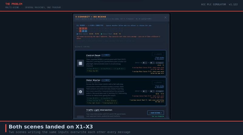
This is not a simulator problem. It is the ordinary problem of I/O allocation. Two identical machines on one PLC cannot both live at X1. Somebody has to decide that the second one starts at X4, write it on the drawing, and wire it that way.
The fix: each scene gets an address offset
When a scene connects, the multi-scene PLC simulator gives it an offset — a number added to every one of its discrete addresses before the program ever sees them.
The scene still knows itself as X1 to X3. It draws its own pushbuttons at its own addresses and it has no idea it has been moved. The simulator does the translation on the link. Your program uses the shifted addresses.
The whole rule is one addition:
PLC address = scene address + that scene’s offset
Applied separately to X and to Y.
| Scene | Offset | Scene’s own addresses | PLC addresses |
|---|---|---|---|
| Motor Starter, connected first | 0 | X1–X3 / Y1–Y3 | X1–X3 / Y1–Y3 |
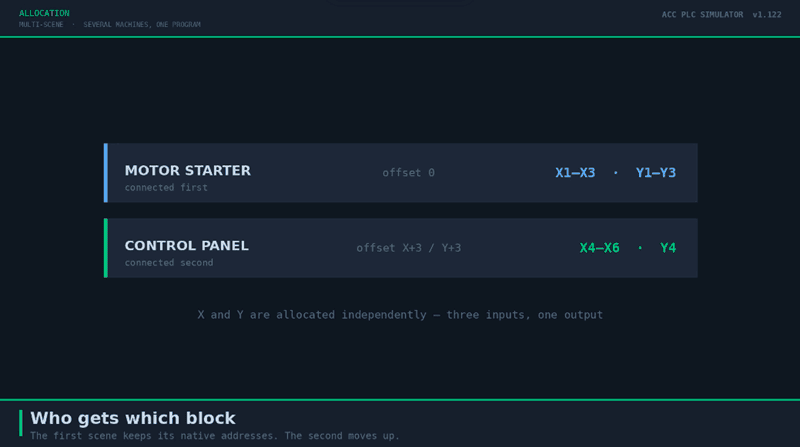
| Control Panel, connected second | X+3 / Y+3 | X1–X3 / Y1 | X4–X6 / Y4 |
X and Y are offset independently, because a machine’s input count and its output count have nothing to do with each other. The Control Panel uses three inputs and one output, so it needs three X addresses and one Y — there is no reason to reserve three of each.
You do not have to work the offsets out yourself
Launch a second scene and the simulator picks its offset for you. It takes the lowest offset on each axis that clears every scene already connected and still fits inside X1–X16 and Y1–Y16. If you want a different allocation, type it — each scene’s card has an X and a Y offset box, and a suggest button that recomputes the lowest free block.
The simulator doesn’t guess the allocation. Each scene declares its footprint in the scene registry, and once a scene is running, what it reports over the link is merged in—and only ever widens the reservation. A stale registry entry can therefore under-declare a scene but never under-reserve its memory. Over-reserving costs you nothing; under-reserving would let two machines overlap.
Three places the offsets are shown
You never have to remember which scene sits where.
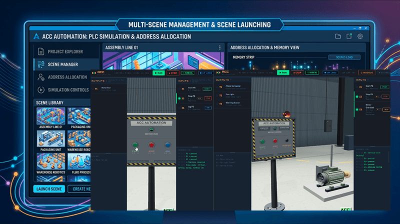
The CONNECT dialog lists every connected scene with its block, like Motor Starter X1–X3 · Y1–Y3.
The PLC memory strip at the top of that dialog draws X1 to X16 and Y1 to Y16 as two rows of cells, colour-coded by which scene owns each address. Free addresses are blank. Contended addresses are flagged.
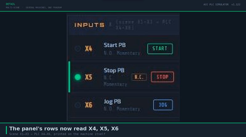
The scene window itself relabels. Once the Control Panel is offset, its input rows no longer read X1, X2, X3 — they read X4, X5, X6, and the panel header reads INPUTS X (scene X1–X3 → PLC X4–X6). The machine tells you where it lives.
A worked example: a remote start station
Here is the example that made me build this. A motor starter in one place, and a remote control panel somewhere else that can start and stop the same motor. Every plant has these. The machine has a local start, and there is a station at the other end of the line that does the same job.
Connect the Motor Starter first, so it takes offset 0. Connect the Control Panel second and it lands at X4–X6 / Y4. Then write one program against both:
(* Motor Starter with a remote Control Panel — two scenes, one program *)
(* Motor Starter   offset 0        X1 Start   X2 Stop N.C.   X3 Overload N.C.
                                   Y1 Contactor   Y2 Run Light   Y3 Warning Horn *)
(* Control Panel   offset X+3 Y+3  X4 Start   X5 Stop N.C.   X6 Jog
                                   Y4 Motor Run Pilot *)

VAR
  PreStart : TON;
END_VAR

(* Either Start button calls for a run. Both Stop buttons and the
   overload are wired normally closed, so they read as XIC contacts. *)
C1 := (X1 OR X4 OR C1) AND X2 AND X5 AND X3;

(* The starter sounds its horn for two seconds before the contactor pulls in *)
PreStart(IN := C1, PT := T#2s);
Y3 := C1 AND NOT PreStart.Q;
Y1 := PreStart.Q;

(* Run light on the starter, pilot light on the remote panel *)
Y2 := Y1;
Y4 := Y1;
Read the first rung, and the feature explains itself. X1 OR X4 is two Start buttons on two different machines. X2 AND X5 There are two Stop buttons in series — press either one and the motor drops out, which is exactly how you would wire two stop stations in the field. X3 is the overload.
Press Start on the Control Panel and the horn sounds on the Motor Starter for two seconds, then the contactor pulls in, the green run light comes on beside it, and the pilot light on the remote panel lights at the same time. Press Stop on either machine and it all drops out.
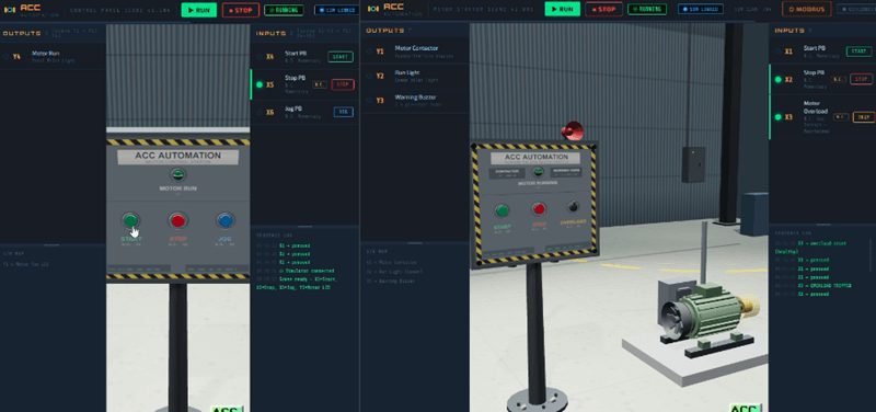
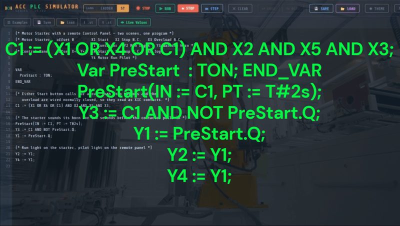
Nobody touched the Motor Starter’s own Start button. The command came from a different scene, through a different block of memory, into one program.
When two scenes do collide
If you put two scenes on the same addresses anyway — and you can, the offset boxes will let you — the simulator tells you rather than leaving you to wonder.
The memory strip marks the contended cells. The card for each scene names the scene it overlaps and the axis it overlaps on. And the banner says what will actually happen: two scenes are writing the same X addresses; they overwrite each other every message, give one of them a different X offset.
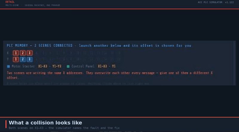
Overlapping outputs is a different matter, and the simulator says so separately. Two scenes sharing a Y address is harmless — outputs are read-only to a scene, so both simply follow the same coil. If you want two pilot lights on two machines to show the same thing, pointing them at the same Y is a legitimate way to do it.
That distinction is worth sitting with. Contending for an input is a fault. Sharing an output is a design decision.
What does not shift
Three exceptions, and they all matter.
Analog does not shift. AX and AY addresses stay exactly where the scene reference lists them. The offset mechanism applies the digital offsets to a much smaller analog space — eight AX and four AY — so analog is dropped on an offset scene. Any scene that uses analog has to be the only connected scene, or the first one launched. In practice: the Tank Fill Station, which reports its level as an analog value, runs at offset 0.
Modbus addresses never shift. Offsets exist only on the link between the simulator and the scene. A scene driven over Modbus TCP from a real PLC is never offset, so X5 is Discrete Input 10005 no matter what else is connected.
A program is not portable across offsets. Logic written for a scene at offset 0 will drive the wrong machine if that scene is later given an offset. Say in your comments which offsets a program assumes — the comment block at the top of the example above is there for that reason, not for decoration.
The limits
Sixteen X addresses and sixteen Y addresses, so that is the ceiling on how much machinery you can connect at once. An offset can be anything from 0 to 15. The Motor Starter and the Control Panel together use six X and four Y, which leaves room for more. The Palletizer alone takes ten X and five Y, so it and one small scene is about the practical limit for that combination.
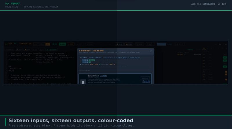
A scene holds its block until you close its window. Close the window and the addresses go back to the pool.
One practical note: each 3D scene is a full WebGL render, and browsers throttle background tabs hard. Run two or three scenes, and you want them in separate windows rather than stacked as tabs in one — the simulator says as much in the CONNECT dialog, and it is worth doing.
Why this is worth teaching
The offsets are not a workaround. They are the lesson.
Every controls technician eventually meets the moment where two identical machines have to live on one processor, and the answer is an I/O allocation — a decision about who gets which addresses, written down so the next person can follow it. Students who only ever program a single machine at X1 never meet that problem. Students who connect a second machine meet it in the first thirty seconds, and the simulator hands them the vocabulary: footprint, block, offset, contention.
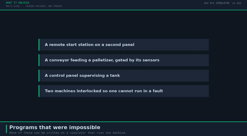
It also unlocks the programs that were impossible before. A remote start station. A conveyor feeding a palletizer, with the palletizer’s cycle gated by the conveyor’s sensors. A control panel that supervises a tank. Two machines interlocked so that one cannot run while the other is in a fault. None of that could be written on a simulator that ran one machine at a time.
Try the multi-scene PLC simulator
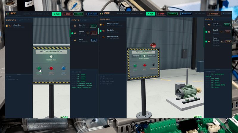
Open the simulator, launch a scene, then launch a second one and watch the memory strip fill in. Press suggest for the tidiest allocation, or type your own offsets if you would rather decide.
- Launch the simulator
- Simulator help
- Scene guide — I/O maps and Modbus addresses
- AI Program Guide — writing programs for the simulator
If you are generating programs with an AI assistant, point it at the AI Program Guide. Section 3.5 covers the offsets, and the assistant needs to know which offsets your scenes use—it can’t see your screen.
If you have any questions or need further information, please contact me.
Thank you,
Garry