We will use the PLC to sort items on a conveyor operating shift register instructions. We will apply the five steps to a PLC example program development of a sorting station. The program will use shift registers to track colored parts down a conveyor and sort, depending on color, into one of three locations.

Developing the PLC program example is a process that can be clearly defined. We have done some similar practical examples in our series on the five steps to PLC program development.
Five Steps to PLC Program Development
– Press
– Process Mixer
– Shift Register (Conveyor Reject)
– Paint Spraying
– Delay Starting of 7 Motors
– Pick and Place
Define the task: (Step 1 – Sorting Station Shift Register)
Watch the sequence of operation video below.
Watch on YouTube: PLC Programming Example – Sorting Station Testing
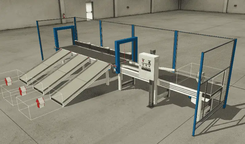
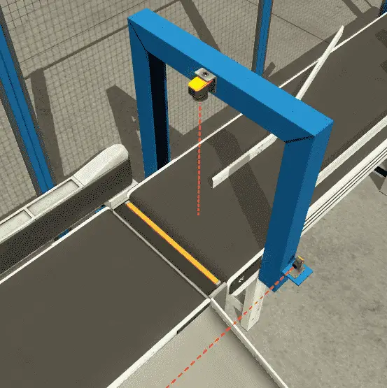
 A normally open start and normally closed stop pushbuttons are used to start and stop the process in automatic mode. Upon beginning the entry, exit, and sorting station, belt conveyors will turn on. This will bring parts to the vision sensor.
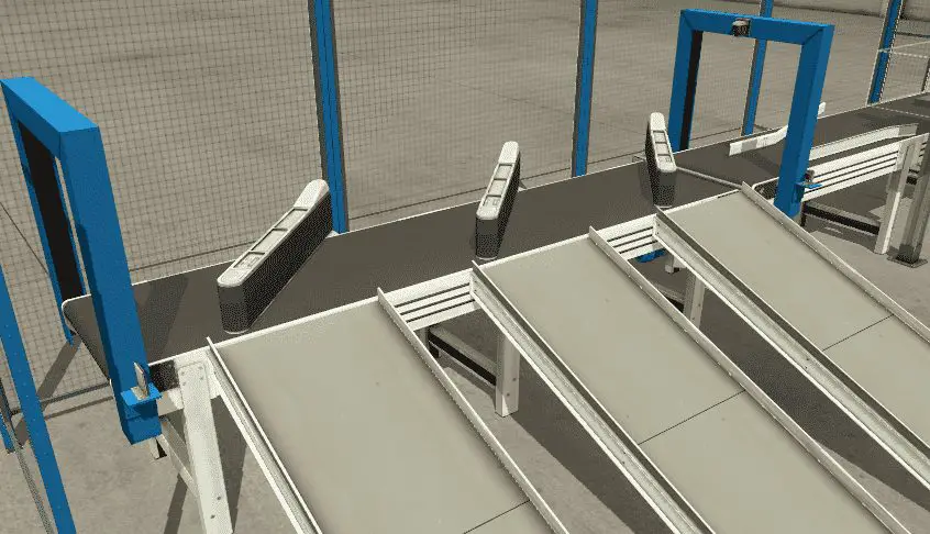
 Each part will be tracked down the conveyor belt until it is in front of the appropriate exit ramp. (Three Ramps)
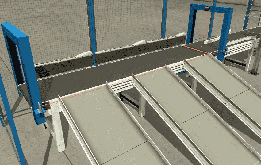 The sorting station diverter for the exit ramp will turn on, allowing the part to slide down the exit ramp.
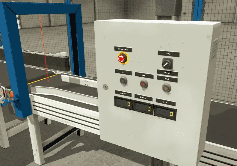
 The number of sorted parts is tracked by a counter that will display the number of features sorted for the exit ramp. Hitting the reset when the panel is in manual mode will allow the counters to reset to zero. (0)
To reset the tracking of the parts and clear the conveyors, hit the reset button when the machine is stopped.
If a part is stuck on the exit sensor to the ramp, this will block the sensor. A delay of 5 seconds takes place, and then the machine will stop. The flashing reset button indicates a jam has occurred at the exit.
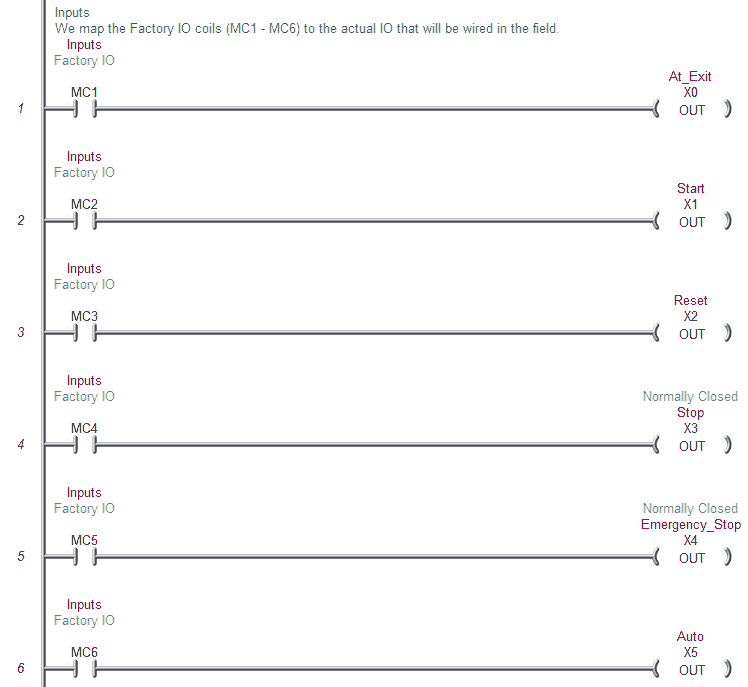
Define the Inputs and Outputs: (Step 2 – Sorting Station Shift Register)
Inputs:
Item at Exit – Sensor – On/Off – Normally Closed
Start Pushbutton – Normally Open – On/Off
Reset Pushbutton – Normally Open – On/Off
Stop Pushbutton – Normally Closed – On/Off
Emergency Stop – Normally Closed – On/Off
Auto / Manual – Switch – On/Off
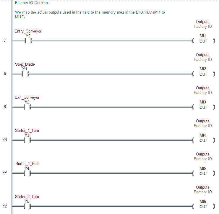
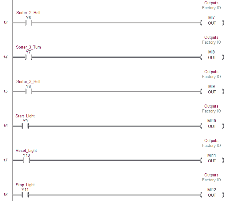
Outputs:
Entry Conveyor – Contactor – On/Off
Stop Blade – (Not used)
Exit Conveyor – Contactor – On/Off
Sorter 1 Turn – On/Off
Sorter 1 Belt – Contactor – On/Off
Sorter 2 Turn – On/Off
Sorter 2 Belt – Contactor – On/Off
Sorter 3 Turn – On/Off
Sorter 3 Belt – Contactor – On/Off
Start Light – On/Off
Reset Light – On/Off
Stop Light – On/Off
Vision Sensor (Colour Sensor) – Register – 16 bits
Counter 1 exit ramp – Register – 16 bits
Counter 2 exit ramp – Register – 16 bits
Counter 3 exit ramp – Register – 16 bits
Develop a logical sequence of operation: (Step 3 – Sorting Station Shift Register)
A flow chart or sequence table is used to understand the process that needs to be controlled thoroughly. It must also answer questions like the following:
What happens when electrical power and/or pneumatic air is lost? What happens when the input / output devices fail? Do we need redundancy?
Knowing all of these answers upfront is vital in developing the PLC program. This step is where you can save yourself a lot of work by understanding everything about the operation. It will help prevent you from continuously re-writing the PLC program logic.
The main part of the program will be to track the pieces down the conveyor belt. Using a shift register on each exit ramp is an excellent way to do this logic.
Here is a review of how shift registers work:
https://accautomation.ca/plc-programming-example-shift-register-conveyor-reject/
In our example, we do not have an input representing movement on the conveyor belt. This would be like a proximity sensor on a sprocket or an encoder on the conveyor shaft. We will accomplish this by using a system timed bit. (100ms interval) When the conveyor belt runs, we will trigger our shift register every 100ms. This will act as the clock input to our instruction. Each 100ms pulse of the bit will indicate a movement of the conveyor belt.
Develop the PLC program: (Step 4 – Sorting Station Shift Register)
Writing the code for the PLC example will be the next step in our program development. A quick review can be seen on our post: Buiding A PLC Program That You Can Be Proud Of
(This series takes you through using discrete inputs and outputs to control traffic lights and cylinders. As we progress, we introduce additional methods to solve logic. We look at sequencers in a new way and learn how to write programs to allow users to teach the new sequence.)
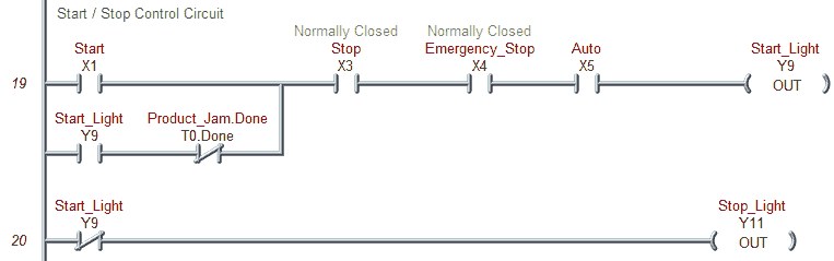
The first thing in our program is to control the start and stop functions. This is done through a latching circuit.
Start / Stop Control Circuit
 Start the conveyors in the system. This is done with the start light bit.
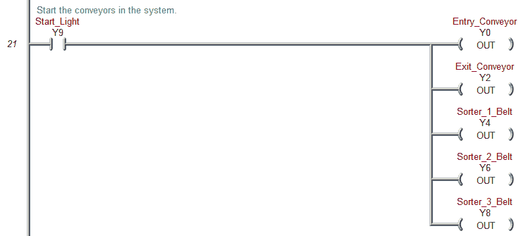 The color sensor on the input (MHR1) will determine the product’s color. The product will be sorted into one of three ramps based on color. The three sorting station ramps are tracked by their shift register.
The clock input to all three shift registers will be the start bit and a 0.10-second system clock bit (100 msec). Usually, this would be off of a conveyor pulse bit representing the distance traveled by the conveyor. Example: Gear turning triggers a proximity sensor.
Reset on the part tracking (shift registers) is done with the reset button when the system has stopped.
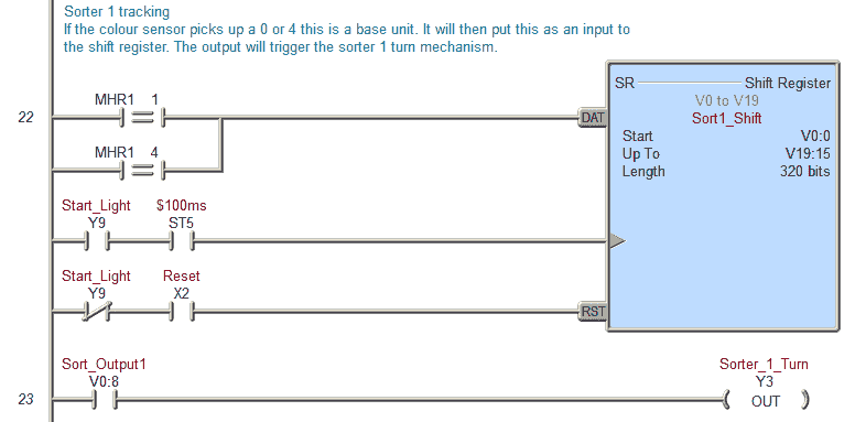
Sorter 1 tracking
This is a base unit if the color sensor picks up a 0 or 4. It will then put this as input to the shift register. The output will trigger the sorter one-turn mechanism.
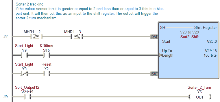
Sorter 2 tracking
If the color sensor input is greater or equal to 2 and less than or equal to 3, this is a blue part unit. It will then put this as input to the shift register. The output will trigger the sorter’s two-turn mechanism.
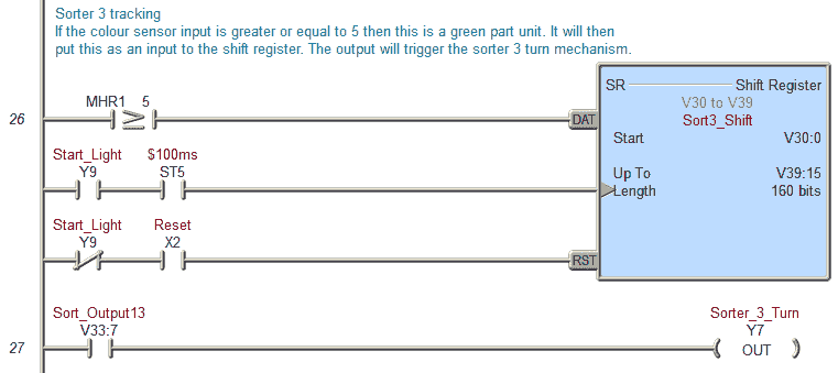
Sorter 3 tracking
If the color sensor input is greater or equal to 5, this is a green part unit. It will then put this as input to the shift register. The output will trigger the sorter three-turn mechanism.
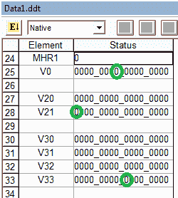
The actual output from each shift register will have to be experimented with during the testing of the program. In our case, Sort1 bit V0:8, Sort2 bit V21:15, and Sort3 bit V33:7 was used.
Counters
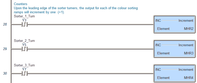 Upon the leading edge of the sorter turners, the output for each color sorting ramp will increment by one (+1).
Reset Light
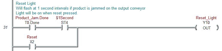 Will flash at 1-second intervals if the product is jammed on the output conveyor
The light will be on when reset is pressed.
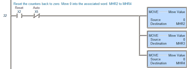 Reset the counters back to zero. Move 0 into the associated word. MHR2 to MHR4
Product Jam
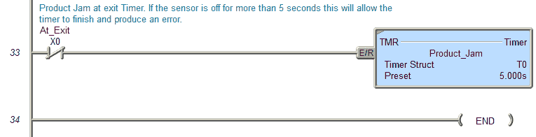
Product Jam at exit Timer. If the sensor is off for more than 5 seconds, this will allow the timer to finish and produce an error.
This is the end of our program.
Test the program: (Step 5 – Sorting Station Shift Register)
We will be using Factory IO to test the program. This communicates Modbus TCP Client (Master) to our BRX Series PLC (Modbus TCP Server (Slave)).
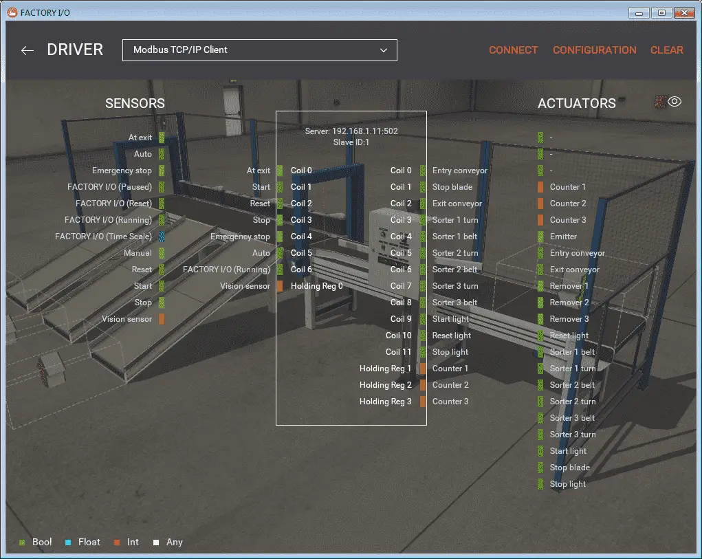 We will now add the inputs and outputs to our program for communication to our scene in Factory IO. The output coils from Factory IO will set the actual input addresses in our PLC example program. This will demonstrate how we can set the actual PLC inputs. See the following post on Understanding the PLC Program Scan.
The actual outputs will set the inputs from Factory IO from our PLC example program.
The first step in testing the program is ensuring that the PLC’s inputs and outputs are wired correctly. We would usually turn each input on manually and see the corresponding input of the PLC turn-on. The same applies to the output devices. We will turn on each of the outputs to determine if they have been wired correctly.
If everything is working, we will start running our program automatically.
Fine adjustments may be required for the output bits of the sequencers. In our example, we use the following bits within each sequencer instruction. (Shift Registers)
Test the program for things that can go wrong. Unplug a sensor or remove a box after the sensor has seen it. The PLC example program should be able to react.
Watch the video below to see an explanation and test of the program using Factory IO.
You can download the program and Factory IO scene here.
Watch on YouTube: PLC Programming Example – Sorting Station
If you have any questions or need further information, please get in touch with me.
Thank you,
Garry
If you’re like most of my readers, you’re committed to learning about technology. Numbering systems used in PLCs are not challenging to learn and understand. We will walk through the numbering systems used in PLCs. This includes Bits, Decimals, Hexadecimal, ASCII, and Floating Points.
To get this free article, subscribe to my free email newsletter.
Use the information to inform other people how numbering systems work. Sign up now.

The ‘Robust Data Logging for Free’ eBook is also available as a free download. The link is included when you subscribe to ACC Automation.
pretty neat. watched the first video. i’ve taken 3 plc courses at a cc in california.
Factory IO is a good program for teaching the basics of PLC programming. Other parts of the program will allow you to make the sensors fault and outputs faults. This way troubleshooting skills can be taught.
Regards,
Garry
hie Garry. lm currently doing a project for parcel sorting system using bar code to scan the destination of the parcel.how do l go about it as in the ladder program.really appreciate all the help
regards
Hi Chizman,
The first step is to establish communication from the bar-code scanner to the PLC. This is usually done by using a receive instruction in the PLC. Do you have a specific bar-code scanner and PLC models that you are using? This will determine the method of getting the information.
Here is a link on how to do this using the Do-More:
https://www.automationdirect.com/videos/video?videoToPlay=JqO0-DNUQSI
Here is a link using the Click PLC:
https://www.automationdirect.com/videos/video?videoToPlay=guYoOZqkulc
The next part to be done is the tracking once the information is in the PLC from the bar-code scanner. I would use compare instructions to determine the destination and then create a shift register. The shift register could be bits like the video above or words.
I hope this helps you out. Let me know how you make out.
Regards,
Garry
hie Garry
can you give me a sample of a bar code reader using plc..its difficult to program it.thank you
Hi Chizman,
See the comment below for examples on connecting a barcode scanner to the Click PLC and the Do-More PLC.
What is the make and model of the barcode scanner that you are using?
What is the make and model of the PLC that you are using?
Making the cable connection can be difficult for the serial connection. What do you have so far?
Regards,
Garry
hi Garry
i wanted to ask for your PLC code you used for the sorting station example.
thank you
Hi Chizman,
You can download the program and Factory IO scene here:
https://www.dropbox.com/s/hidlidvh6czvvkn/PLC%20Programming%20Example%20-%20Sorting%20Station%20%28Shift%20Register%29.zip?dl=0
Regards,
Garry
Chizman,
No offense but how did you get hired doing this project? It seems like you have minimal , or no PLC programming experience. PLC’s programming is something serious that if it isn’t done by a professional could result in damage to equipment, serious injury to people, or worst case death. If you are serious in the questions you’re asking, you should consider not doing this project.
Vince
hie garrys
can you help me out with a PLC code for the sorting station but instead of 1 conveyor belt ,they will be 2 or 3 conveyor belts running on the same speed
regards
chizman
Hi Chizman,
You can add many different shift registers as you would like to represent multiple conveyors. If they are all running the same speed, then the clock pulse would be the same for all of them. Outputs would trigger on each line depending on the location that you want something to happen.
I hope this helps you out.
Regards,
Garry
hie Garry
l want to use the datalogic DS2100-1110 bar code scanner.
the PLC l want to use the siemens S7-313C CPU
can these work for my project which l want to explain below
l want to design an automatic parcel sorting machine in which the destination of the parcel is extracted by the bar code and processed by the PLC.once the parcel have reached its sorting area it is deflected to the destination loading bay..the concept is almost the same as the one in your video only that l want to use bar code reader to determine where its being deflected.
Hi Chizman,
I have not worked with this barcode scanner but looking at the specifications it should work. It will communicate to the PLC via RS232.
http://content.etilize.com/User-Manual/1012065706.pdf
The S7-313C does not have a serial port (RS232) so a communication module with a serial interface (RS232) (6ES7 138-4DF01-0AB0) must be used.
The first thing to do is to establish communication from the barcode scanner to the PLC. Here are some threads that may help you out.
http://www.plctalk.net/qanda/showthread.php?t=40683
http://www.plctalk.net/qanda/showthread.php?t=36901
Once your communication link is established, I would then concentrate on the tracking part of the program.
Hope this helps you out.
Regards,
Garry
Hi Chizman,
This is a nice article. You mentioned the outputs from the shift register were determined by experiment. Is it determined by the location of the three sorters?
Hi Chizman,
The output would be based on the timing of when you want it to activate. If the clock pulse to activate the shift register is based on an encoder then you would determine the number of pulses required to trigger the output.
Hope this helps you out.
Regards,
Garry
hie garry
can you help me by writing a PLC program of an additional conveyor belt next to the existing one so that the sorting will be done by 2 stations running with the same speed,side by side
using 1 PLC code
Hi Chizman,
In order to have 2 stations running side by side then use two shift registers with the same clock pulse. The input to the shift registers may or may not be the same depending on the application.
I hope this helps you out.
Regards,
Garry
thanks for your use full examples ,is it possible to test your example without hardware plc in pc and run factory i/o scene .
please tell how ,thanks in advance
Hi Javad,
You can connect Factory I/O to the Do-More Designer software. This is a fully functional free download.
https://support.automationdirect.com/products/domore.html
You can also use AdvancedHMI on the same PC.
https://sourceforge.net/projects/advancedhmi/
Here is a post that will cover the installation of the Do-More Designer simulator and AdvancedHMI on your PC.
https://accautomation.ca/create-a-plc-with-hmi-training-and-learning-environment-free/
Video
https://youtu.be/1rWI-A-nZdo
I hope this will help you out.
Regards,
Garry
hie garry
im using simatic manager s7 pro for my project but the problem is the simulation on/off button is not working.can you give me some ideas on how to toggle it to the on mode
regards
Hi Chizman,
Here is a link dealing with setting up the S7 with Factory IO.
https://factoryio.com/docs/tutorials/siemens/setting-up-s7-plcsim-v13/
Hope this helps you out.
Regards,
garry
hie garry
can you give me the steps l have to take to import the plc program you sent me into my simatic s7 and also the scene to my factory io
Hi Chizman,
The Factory IO scene can be downloaded at the following location:
https://www.dropbox.com/s/hidlidvh6czvvkn/PLC%20Programming%20Example%20-%20Sorting%20Station%20%28Shift%20Register%29.zip?dl=0
Since this program was written for the Do-More PLC you will have to re-write the program for the S7.
The shift register for the S7 can be found on this thread.
http://www.plctalk.net/qanda/showthread.php?t=19010
I hope this helps you out.
Regards,
Garry
hello garry
l downloaded the do more PLC software
my question is what is the name of the PLC will l be simulating.is it the Siemens or Allan Bradley or the mitsubishi
Hi Chizman,
The Do-More Designer Software will program the Do-More Series of PLCs. This includes the H2, T1H, and BRX.
https://www.automationdirect.com/adc/overview/catalog/programmable_controllers/do-more_series_(brx,_h2,_t1h)_plcs_(micro_modular_-a-_stackable)
The simulator will allow you to run your PLC code without having one of the above physical PLCs.
Here is a series on the Do-More Software:
https://www.youtube.com/playlist?list=PL3y71jAPOdZB5LJMMotZP36LvzfdgkgzW
Regards,
Garry
Hello
I get it now..so the do more series plc,click series plc and the directlogic series plc are other types of plc manufacturers just like the siemens and allan Bradley
coming back to the sorter system of the code you sent and factory io scene,how do l link the factory io and do more software so that l can run the code.
Hi Chizman,
Factory IO Website is at the following URL:
https://factoryio.com/
Documentation is well done. Start at the ‘Getting Started’ at the following URL:
https://factoryio.com/docs/
The above links should help you out.
Regards,
Garry
hie Garry
can l have your email address so that l can communicate with you more efficiently.l do have some image attachments l will be sharing with you in need of your help.
thank you
Hi Chizman,
You can reach me at garryshortt@accautomation.ca
Regards,
Garry
hello garry
can l have your email address.l would very much like to continue asking for your help including sending you image attachments of the problems l am facing
thank you
Hi Chizman,
You can reach me at garryshortt@accautomation.ca
Regards,
Garry
Hie garry
Which OFFLINE PLC type and sub-type do l use for the simulation of the sorting station.the error lm getting l sent it as an attachment to your email you gave me
Regards
Hi Ham Chizman,
The Do-More Simulator will use the same IP address as the Host Computer. This cannot be changed unless the computer changes. See the following post from the Forums:
https://forum.automationdirect.com/forum/general-applications/do-more-series-plc/111488-connecting-an-hmi-simulator-to-the-do-more-simulator
The PLC that you will choose is the DM-SIM. This is the Do-More Simulator.
If you were to call up the program that was made for the sorting station, all of the setting should be fine except for the IP address.
Regards,
Garry
Hello,
Thank you for sharing this content. Do you have the program written in stucture text by any chances? This would help a lot.
Hi Kevin,
Thank you for the comment. I do not have this program written in structured text.
Regards,
Garry
Hello,
Thank you for sharing this content. Do you have the program written in stucture text by any chances? This would help a lot.
Thanks in advance.
Kind regards
Kevin
Hi Kevin,
Thank you for the comment. I do not have this program written in structured text.
Regards,
Garry