Data handling instructions are used to perform movement and manipulations of the memory in the programmable logic controller. The Productivity 1000 Series PLC has fifteen different data handling instructions that can be used in a wide variety of applications. In this first part we will be looking at the following instructions:
Absolute Encoder (ABSE) – Encoder input using Gray Code or Binary Code
Compare Values (CMPV) – Compare two different tags and determine if equal, greater than, or less than.
Copy Data (CPD) – Copy tags from one location and place them in another.
FIFO / LIFO (FILI) – First in first out / Last in first out
First Bit On/Off (FIB) – Determines first bit on in a series of bit tags.
Inc / Dec (INC) – Increment or decrement a tag by a number.
Logical Bits (LOG) – Perform logical operations on Boolean input tags.
Logical Words (LOGW) – Perform logical operations on tags.
In part 2 of data handling, we will continue with additional data handling instructions.
Let’s get started with the Productivity 1000 Series PLC data handling instructions.
Previously in this Productivity 1000 series PLC we have discussed:
System Hardware – Video
Installing the Software – Video
Establishing Communication – Video
First Program – Video
Documenting the Program – Video
Monitoring and Testing the Program – Video
Online Editing and Debug Mode – Video
Numbering Systems and Tag Database – Video
Contact and Coil Instructions – Video
Timer Instructions – Video
Counter Instructions – Video
Math Instructions – Video
Absolute Encoder (ABSE) – Productivity Data Handling
This instruction will decode Bit Patterns (maximum 12 bits) from Gray Code or Binary Absolute Encoder.
Here’s a Quick Way to Convert Grey Code into Binary for PLC – This post will show you the logic behind this instruction.
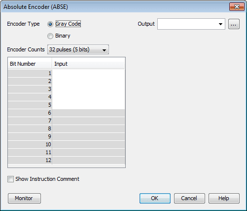
Select the Encoder Type. Gray Code or Binary
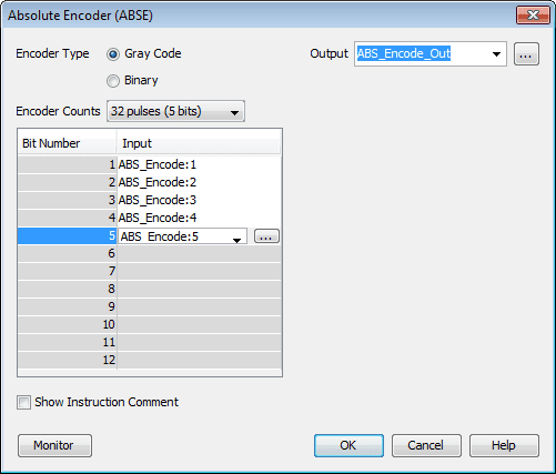
We will select the Gray Code 5 bit. This will give us 32 pulses per revolution. The output tag will be called ABS_Encode_Out. Inputs will be ABS_Encode:1 to 5.
Note that the colon means the bit of the tag.
Select OK.
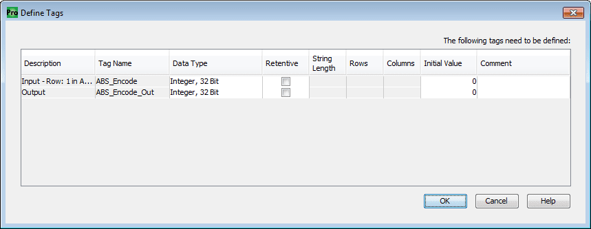
This will bring up a window showing to tags that we used in the instruction. We can now select the properties of the tags and select OK.
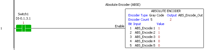
When Switch1 is turned on the instruction will encode the 5 bits of tag ABS_Encode and output to tag ABS_Encode_Out.
Here is a chart of the 5 bit Gray Code.
| Decimal | Binary | Grey Code |
| 0 | 00000 | 00000 |
| 1 | 00001 | 00001 |
| 2 | 00010 | 00011 |
| 3 | 00011 | 00010 |
| 4 | 00100 | 00110 |
| 5 | 00101 | 00111 |
| 6 | 00110 | 00101 |
| 7 | 00111 | 00100 |
| 8 | 01000 | 01100 |
| 9 | 01001 | 01101 |
| 10 | 01010 | 01111 |
| 11 | 01011 | 01110 |
| 12 | 01100 | 01010 |
| 13 | 01101 | 01011 |
| 14 | 01110 | 01001 |
| 15 | 01111 | 01000 |
| 16 | 10000 | 11000 |
| 17 | 10001 | 11001 |
| 18 | 10010 | 11011 |
| 19 | 10011 | 11010 |
| 20 | 10100 | 11110 |
| 21 | 10101 | 11111 |
| 22 | 10110 | 11101 |
| 23 | 10111 | 11100 |
| 24 | 11000 | 10100 |
| 25 | 11001 | 10101 |
| 26 | 11010 | 10111 |
| 27 | 11011 | 10110 |
| 28 | 11100 | 10010 |
| 29 | 11101 | 10011 |
| 30 | 11110 | 10001 |
| 31 | 11111 | 10000 |
Compare Values (CMPV) – Productivity Data Handling
This instruction will set greater, less, and equal bit flags based upon the comparison of two tags.
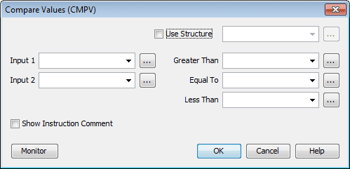
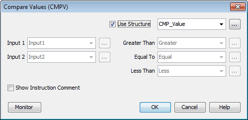
Select use structure and name this CMP_Value. This will automatically set the tags for Input 1 and 2 as well as the three Boolean flags.
Select OK.
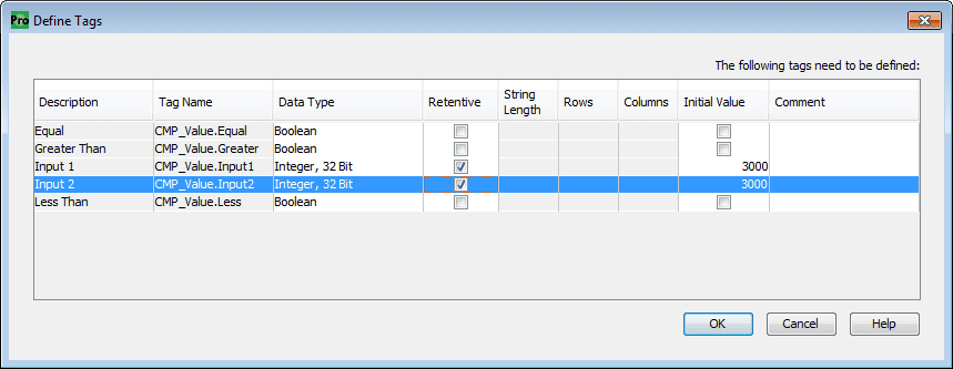
We will make the Input 1 and 2 memory retentive and set the value to 3000 for each one.
Select OK.
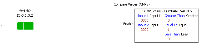
When Switch2 is on, input 1 is compared to input 2. In our example, they are equal so the equal bit flag is on.
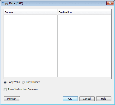
Copy Data (CPD) – Productivity Data Handling
This instruction will copy the data or binary pattern from the specified source tags to the corresponding destination tags.
We will copy the value of the CMP_Value.Input1 tag to CMP_Value.Input2 tag.
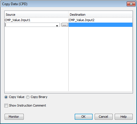
Select OK.
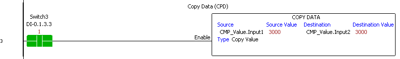
When Switch3 is on the value is copied from the source to the destination every scan.
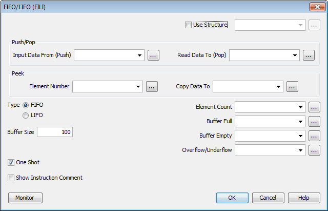
FIFO / LIFO (FILI) – First in first out / Last in first out – Productivity Data Handling
This instruction will allow data to be added (pushed), removed (pulled, popped) or viewed (peek) from a block of memory (buffer).

The above is an analogy of the FIFO / LIFO instruction. The tennis ball sleeve represents the block of memory and each ball in it represents one number. Our ball sleeve can have any number of balls in it at a given time and will expand or contract to suit our needs.
When we add a ball to the sleeve, this is a push.
When we remove a ball from the top of the sleeve this is a LIFO (Last in first out.) pull.
Removing a ball from the bottom of the sleeve would be a FIFO (First in first out.) pull.
At any time we can take a look at the balls in the sleeve. This would be a PEEK.
We will use structure to set up the tags. Call the structure FIFO_LIFO. The type will be FIFO (first in first out). We will set the one shot on the inputs so the inputs will only trigger from an off to on state for one scan of the PLC.
How to make a one-shot in the PLC – Video
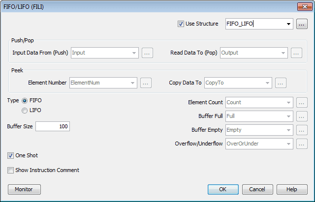
Select OK.
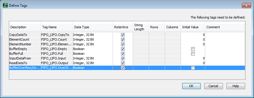
We can now define our tags. Making our tags retentive will ensure we will not lose the data in our memory block when power is lost to the PLC or the PLC is switched to program mode.
Select OK.
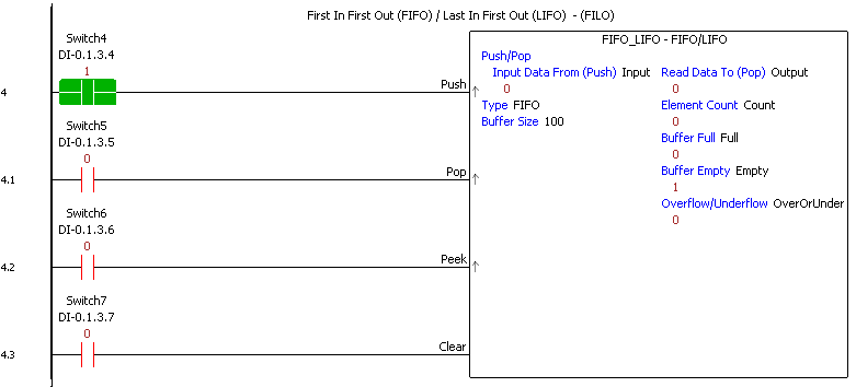
Switch4 is our one shot push input. When this is on it will move the input data to the memory buffer.
Switch5 is our one shot pop input. This will remove information from our memory buffer and place it in the output. Since we are using a FIFO, the first input will be the first output in the buffer.
Switch6 is the one-shot peek input. The element number of the memory buffer will be copied to the CopyTo tag.
Switch7 is a clear instruction. This will clear the buffer and turn on the buffer empty bit.
First Bit On/Off (FIB) – Productivity Data Handling
This instruction determines the first bit in a series of bit tags.
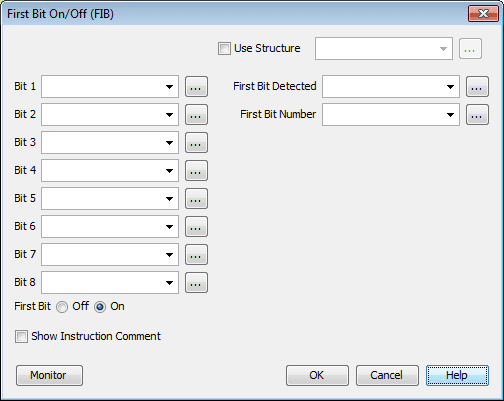
We will use the structure named First_Bit. This will set up Bit1 to Bit8 for the inputs to monitor. The first bit detected and first-bit number will be set as the outputs when the instruction input rung is on.
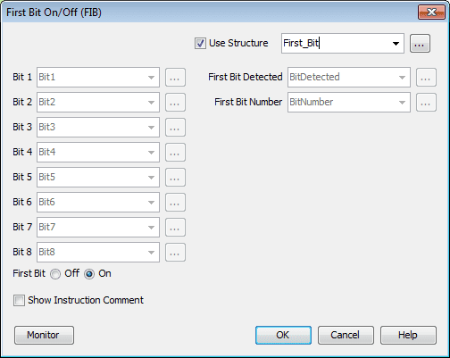
Set the First Bit On selection and hit OK.
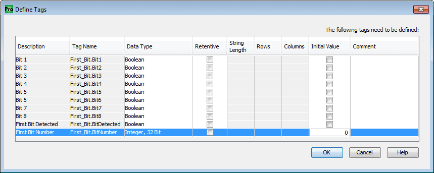
We can now define our tags used in the instruction. Select OK.
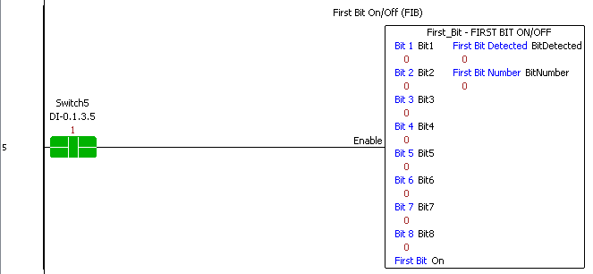
When Switch5 is turned on the inputs are scanned and the outputs are set when the first bit is detected.
Inc / Dec (INC) – Productivity Data Handling
This instruction will increment or decrement a tag by a specific number.
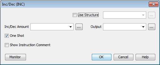
We will use Inc_Dec as the structure name. Select the One-Shot for the input so our increment and decrement will happen only on a transition from off to on.
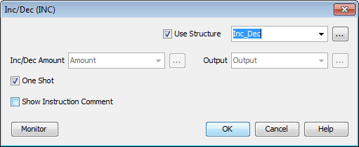
Select OK.
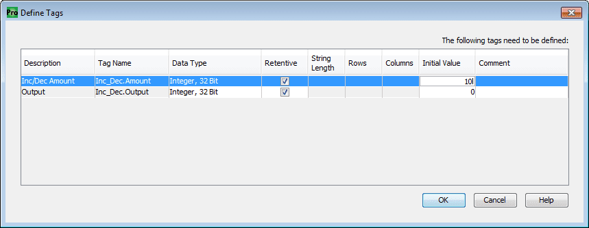
We will make the Inc_Dec. Amount retentive and set the initial value to 10. Our increment and decrement will be by a value of 10 each time. Set the Output also retentive.
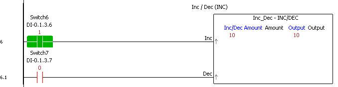
When Switch6 is on the output is incremented by 10. Switch7 will decrement the output by 10 each time.
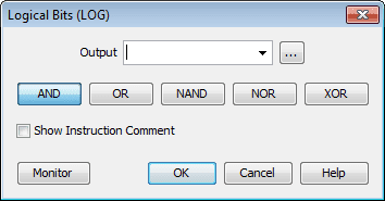
Logical Bits (LOG) – Productivity Data Handling
This instruction will perform logical operations on the boolean input tags.
We will set the output to Logical_Bit_Out flag. This will be the result of our NAND expression that we will also set.
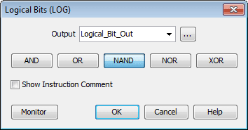
Select OK.
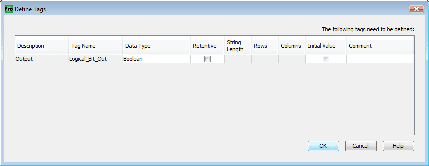
We can then define our tag for the output. Select OK.
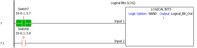
Our logical NAND operation will be performed with Switch7 (Input 1) and Switch8 (Input 2).
Note: Multiple Boolean conditions could be entered for each of the rung inputs.
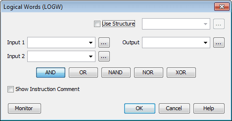
Logical Words (LOGW) – Productivity Data Handling
This instruction will perform logical operations on tags.
We will use Logical_Words as the structure name for the instruction. Our logical operation will be AND.
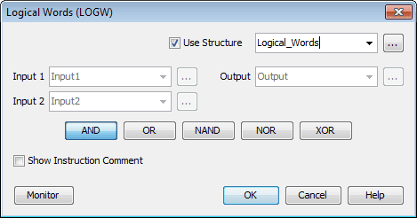
Select OK.
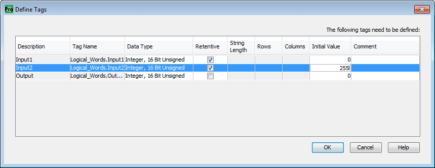
We will make the two inputs of memory retentive. Input2 will have an initial value of 255. This is equivalent to having the first 8 bits on in the memory.
Select OK.
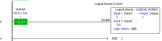
When Switch8 is on we will look at input 1 and perform a logical AND with input 2. Since input 2 has the value of 255. (0000 0000 1111 1111) only the last 8 bits of input 1 will be transferred to the output. We have masked the other bits from the input 1 number.
Download the PLC program here.
Watch the video below to see the data handling instructions used in our Productivity 1000 Series PLC.
Productivity 1000 Series PLC from Automation Direct
Overview Link (Additional Information on the Unit)
Configuration (Configure and purchase a system – BOM)
User Manual and Inserts (Installation and Setup Guides)
Productivity Suite Programming Software (Free Download Link)
This software contains all of the instruction sets and help files for the Productivity Series.
Next time we will continue to look at data handling instructions in the Productivity 1000 Series PLC.
Watch on YouTube: Productivity 1000 Series PLC Data Handling Instructions Part 1
If you have any questions or need further information please contact me.
Thank you,
Garry
If you’re like most of my readers, you’re committed to learning about technology. Numbering systems used in PLC’s are not difficult to learn and understand. We will walk through the numbering systems used in PLCs. This includes Bits, Decimal, Hexadecimal, ASCII and Floating Point.
To get this free article, subscribe to my free email newsletter.
Use the information to inform other people how numbering systems work. Sign up now.

The ‘Robust Data Logging for Free’ eBook is also available as a free download. The link is included when you subscribe to ACC Automation.