The productivity suite programming software has a debug mode. This will allow you to view and control the rung execution on your ladder logic code. These programming tools allow you to troubleshoot, find, and correct errors in the PLC programming logic.
 We will be adding a couple of rungs to our exiting start-stop circuit we created last time in our productivity 2000 PLC. Using the debug mode we will explain the scan of the PLC and use these tools to sequence the logic. Let’s get started.
Previously in this Productivity 2000 series PLC, we have discussed:
P2000 Hardware Features – Video
Productivity Suite Software Install – Video
Communication (System Configuration) – Video
First Program – Video
Productivity 2000 Series PLC Sample Program
Last time we created a start-stop circuit for our first program.
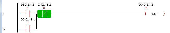 The first simulator input switch would turn on the first output. This output would then seal the input switch so the output could remain on even when the switch turns off. The second switch of the simulator input was normally closed and would stop the output.
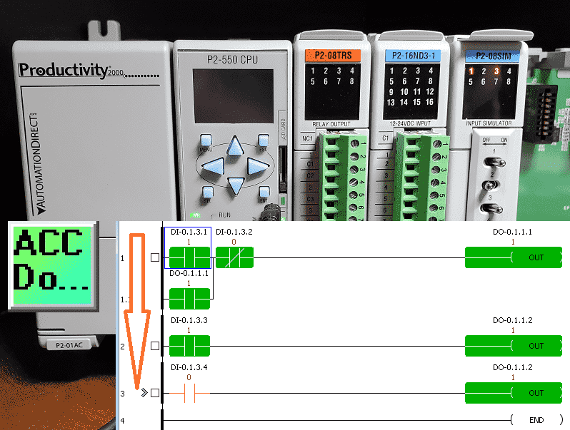
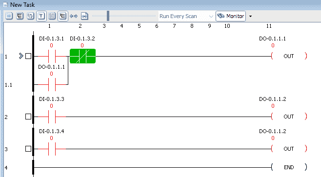
 We will add the following two rungs to our existing program and transfer them to the productivity 2000 PLC controller. Switch 3 will control the second output using a normally open (NO) contact on rung 2. Rung 3 will use the normally open (NO) contact to also control the same second contact.
You can download this simple program here. Save and download the ladder logic code to the PLC. We can then monitor the logic online.
Productivity CPU Scan Time
“Get CPU Scan Time” is used to view the amount of time it takes for the CPU to execute one scan.
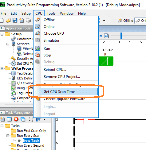 Select “Get CPU Scan Time” from the main menu | CPU.
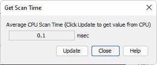 The average scan time is 0.1 milliseconds. This means that in one second the productivity 2000 PLC CPU will scan 10000 times.
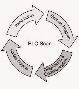 This cyclic scan consists of reading inputs, executing the program, diagnostics, and communication, and updating outputs. The speed of the scan time is too quick to troubleshoot our logic. This is why we will use the debug mode of the productivity suite programming software.
Accessing Debug Mode in Productivity Suite
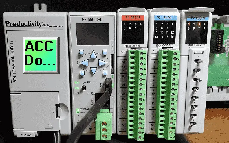
To enable Debug Mode the CPU must be Online and the CPU Mode Switch must be in the RUN position. The stop mode must be activated through the software.
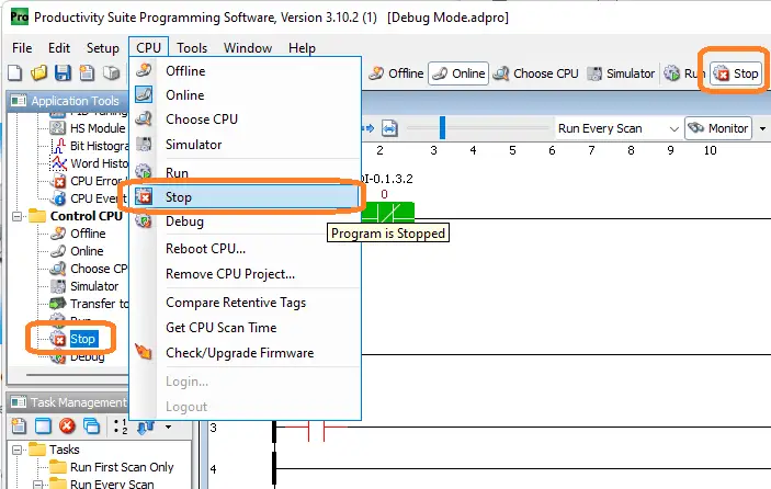 Stop mode can be activated in three different ways. It can be selected on the main menu icon or through the main menu | CPU | Stop. You can also select it under the control CPU in the application tools. Once the PLC is stopped, debug mode can be enabled.
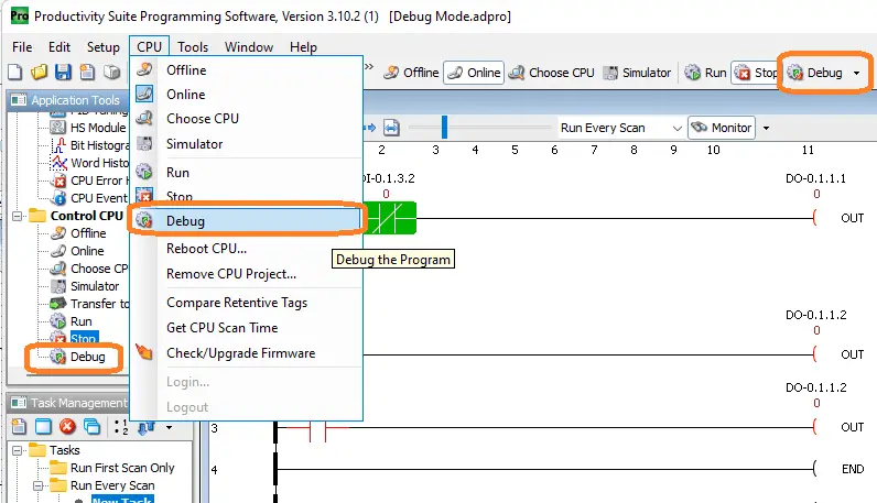 Debug mode can be accessed in three different ways. You can select the main menu icon or through the main menu | CPU | Debug. Under the control CPU in the applications tools, you will also be able to select debug.
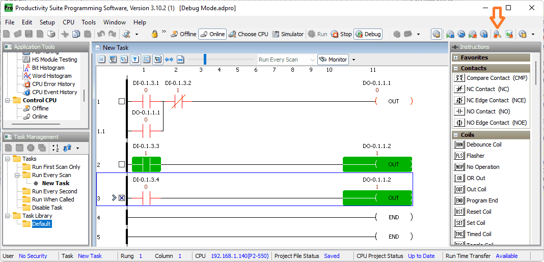
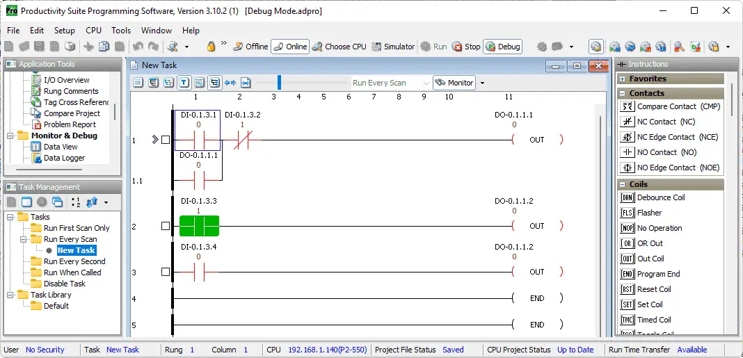
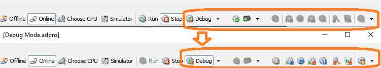 Once you have selected debug mode several icons will now be available for selection. This toolbar will help you troubleshoot your ladder logic program code.
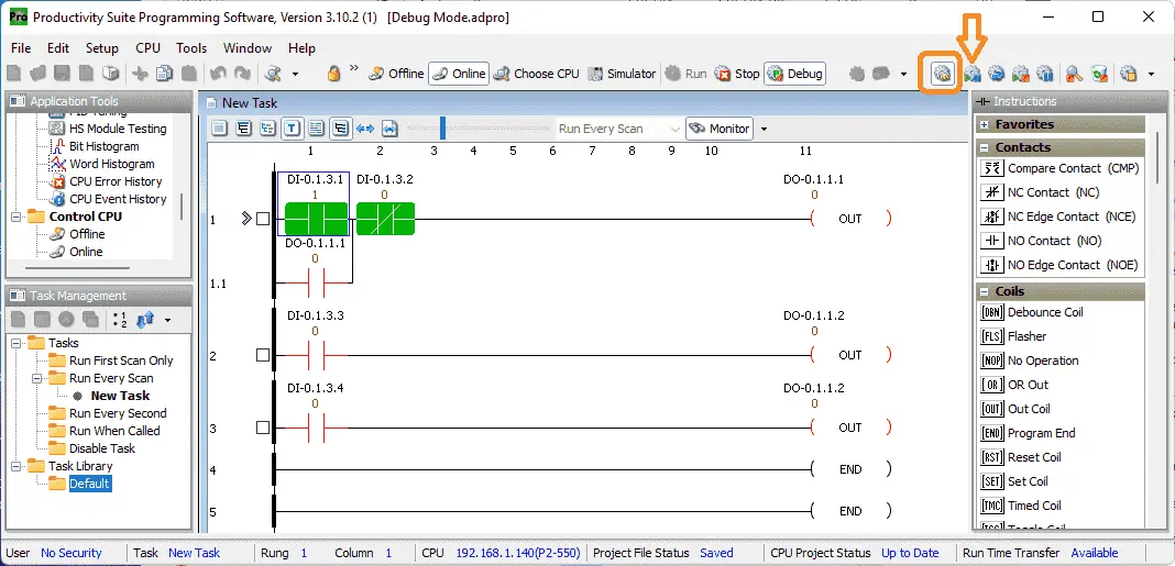
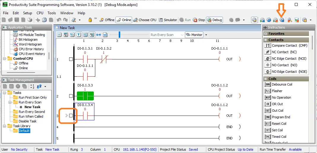
The ladder editor window will also show additional indicators.
 The arrow icon (>) indicates the current step or rung location that you are debugging. The box icon beside each step or rung allows you to set up breakpoints. Clicking on the box will allow you to put an X in the box. This will allow you to run your ladder logic up to that point and stop.
Productivity Debug Toolbar
The debug toolbar is only available in the debug mode of the controller. It has several tools that will aid in troubleshooting the ladder logic PLC program code.
 Execute Outputs Icon – If you do not select this option, you can step through the code without turning on any outputs (Safe Mode).
 Single Step Icon – Single Step allows you to manually step from rung to rung and monitor results.
Run 1 Scan Icon – Run 1 Scan lets you cycle through your entire project once then stop for evaluation.
Run To BP Icon – Run to BP (Breakpoints) allows the option to execute up to a specified point then halt.
Stop Icon – Stop lets you stop any active debug process.
 Show all Breakpoints Icon – Show all Breakpoints gives you a list of all rungs with active breakpoints selections in a debug breakpoints window.
Clear all Breakpoints Icon – Clear all Breakpoints will deselect all selected breakpoints.
 Go to Current Rung Icon – Go to Current Rung will automatically go to the current rung while in Debug Mode.
Watch the video below to see the different debug icons in action with our productivity 2000 PLC.
Productivity 2000 PLC Program Debugging
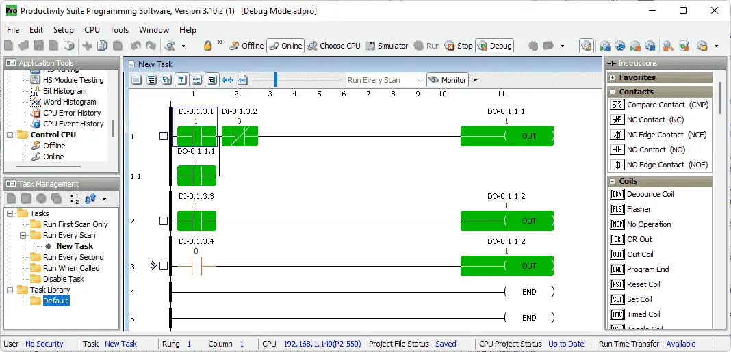
Monitoring our program we can now troubleshoot our ladder logic sample program. Select the execute outputs icon. The physical outputs will be turning on/off. Turn on switch 1.
 Notice that we are currently on rung 1 of our program. Select the single-step icon.
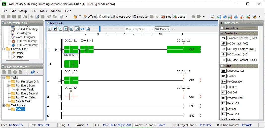
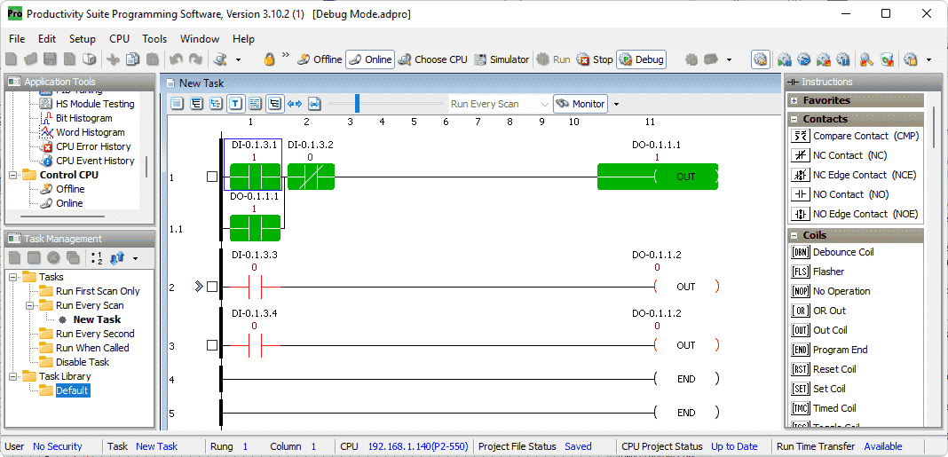 Rung 1 of our program gets executed and stops at rung 2. The output in the first rung will now be set to come when the outputs get updated at the end of the scan. Turn on switch 3. Select the single-step icon again.
 Rung 2 of our program gets executed and stops at rung 3. The second output is now also set to come on at the end of the PLC scan. What do you think will happen once we select the single-step icon again?
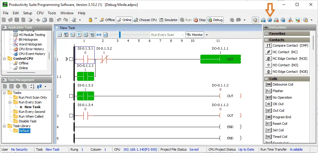
 Rung 3 of our program gets executed. This turns off the second output. The end of the PLC scan is reached so the program will set the outputs based on our ladder logic conditions. Only the first output is physically on. In PLC ladder logic, the last rung controls the physical output.
 Now turn off switch 1 and turn on switch 2. We are currently on the first rung of our program as shown by the arrow icon. Select the run 1 scan icon.
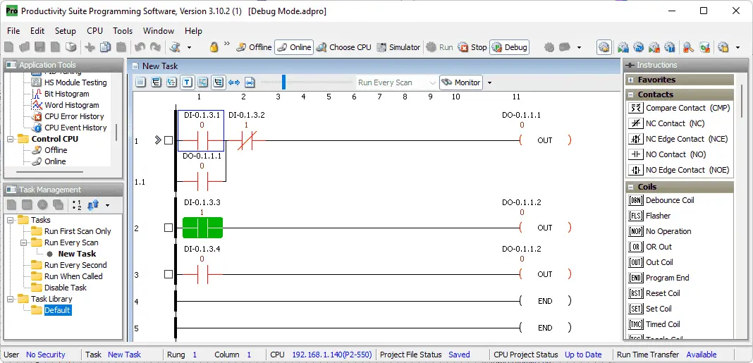 The PLC will execute one scan of the logic. This results in the output turning off on the first rung. Select a breakpoint on rung 3 by clicking the box with your mouse. This will put an X in the box.
 Select the run to breakpoint icon.
 The execution of our PLC logic stopped on rung 3 where we set the breakpoint. Select the show all breakpoints icon.
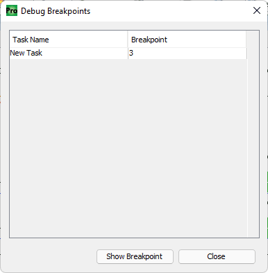 This will display the debug breakpoints window. Highlighting the breakpoint and selecting “Show Breakpoint” will quickly move you around to the different breakpoints set in your program. Select close to close the window.
 Select the clear all breakpoints icon.
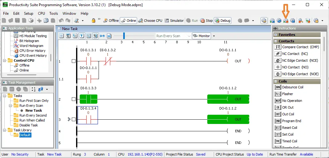 The breakpoints will all be cleared. As you can see our one point has now been cleared. This is very helpful in a large program. What happens when we select the run to breakpoint icon when we have no breakpoints set?
 The arrow showing the step that we are on is faded out. This means that the PLC is cyclically scanning our program. Try testing the logic. Selecting the stop icon will stop the scanning of the logic. The program will stop on the first rung of our ladder logic.
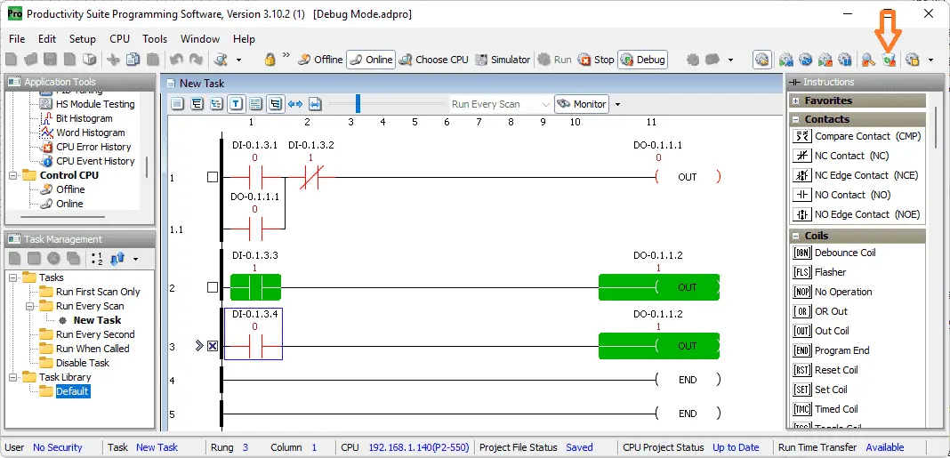
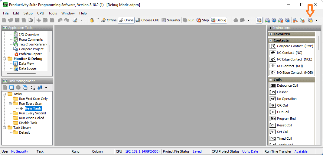 Close the new task with our existing ladder logic code. Select the go to the current rung icon.
 This will display the current task and rung. Select the stop icon to go out of debugging mode.
 Watch the video below to see this in operation.
Productivity 2000 Features (P2000)
- CPU with 5 communication ports
- OLED message display on the CPU module
- Plenty of discrete and analog I/O modules
- Status displays on all discrete I/O modules
- OLED data display on analog modules
- P2-RS remote I/O expansion module, or use the Productivity1000 P1-RX remote expansion module to add even lower-cost remote I/O to your system
- FREE full-featured Productivity Suite software
- Programming with several ports – USB, Ethernet, Serial
- Hardware auto-discovery
- Hot-swappable I/O
- Choose from three wiring options
- Slim DIN rail density form factor:
- hardware – power supply, CPU, and seven modules in only 10-1/2 inches
- All project files (program, tag name database, and all the program documentation) in the CPU
- Run-time editing and debug mode on CPU
- Easy data logging with micro SD on CPU
- Secure Web server to access data files and system tags
- Easy drive and motion controller integration
- Coordinate motion control with PS-AMC allows control of up to 16 axes and synchronization of up to 4 axes
- Two-Year Warranty
Productivity 2000 Series PLC from Automation Direct
Overview Link (Additional Information on the Unit)
Configuration (Configure and purchase a system – BOM)
User Manual and Inserts (Installation and Setup Guides)
Productivity Suite Overview (Features of the fully functional free software package for the Productivity Family of PLC (PAC) controllers)
Productivity Suite Programming Software (Free Download Link)
This software contains all of the instructions and helps files for the Productivity Series.
Watch on YouTube: Productivity 2000 Series PLC Debug Mode
If you have any questions or need further information please contact me.
Thank you,
Garry
If you’re like most of my readers, you’re committed to learning about technology. Numbering systems used in PLCs are not difficult to learn and understand. We will walk through the numbering systems used in PLCs. This includes Bits, Decimal, Hexadecimal, ASCII, and Floating Point.
To get this free article, subscribe to my free email newsletter.
Use the information to inform other people how numbering systems work. Sign up now.

The ‘Robust Data Logging for Free’ eBook is also available as a free download. The link is included when you subscribe to ACC Automation.