The High-Speed Input Pulse Catch will set an output that can be seen by the PLC ladder logic scan in response to an input pulse. Inputs that are too fast to reliably be seen by the ladder logic scan time will be seen.
 The BRX Do-More series of programmable logic controllers have built-in high-speed inputs. These inputs can function in Counter, Timer, or Pulse Catch modes. Every CPU will have either 6 or 10 high-speed inputs (HSI) available depending on the model. These inputs can be used for input frequencies from 0 to 250Khz. 250Khz represents 250000 input counts per second that can be coming from devices connected to your PLC like an encoder. Due to the speed of the inputs, they function on the BRX Do-More PLC asynchronous with the PLC scan time.
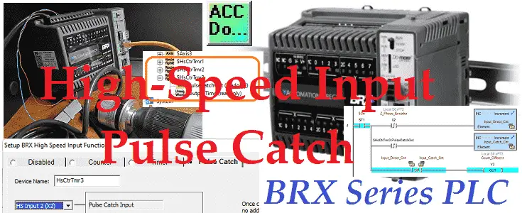
We will continue looking at the high-speed inputs on our BRX Do-More PLC, by looking at the pulse catch mode. The pulse catch mode will be set up using the Z phase of our incremental encoder. Pulses will be counted using the input directly in the ladder logic and using the pulse catch bit. Comparisons will be made between the two counts and an output will be turned on when different. Let’s get started.
Previously in this BRX series PLC, we have discussed:
System Hardware – Video
Unboxing – Video
Installing the Software – Video
Establishing Communication – Video
Firmware Update – Video
Numbering Systems and Addressing – Video
First Program – Video
Monitoring and Testing the Program – Video
Online Editing and Debug Mode – Video
Timers – Video
Counters – Video
High-Speed IO – Video
Compare Instructions – Video
Math Instructions – Video
Program Control – Video
Shifting Instructions – Video
Drum Instruction – Video
Serial Communication – Modbus RTU to Solo Process Temperature Controller – Video
Data Logging – Video
Email – Text SMS Messaging Gmail – Video
Secure Email Communication Video
AdvancedHMI Communication – Modbus TCP – Video
Analog IO – System Configuration – Video
HTTP JSON Instructions – Video
Analog Dusk to Dawn Program – Video
INC DEC 512 Registers for DMX512 – Video
PID with PWM Output – Video
PID Ramp Soak Profile – Video
Do-More Simulator MQTT Publish / Subscribe – Video
BRX Do-More PLC MQTT Communications – Video
Stride Field Remote IO Modules Modbus TCP Ethernet
– Unboxing SIO MB12CDR and SIO MB04ADS Video
– Powering and Configuring Video
BRX Do-More PLC to Stride Field IO Modbus TCP – Video
BRX Do-More PLC Ethernet Remote IO Controller BX-DMIO
– Unboxing BX-DMIO Video
– Configuration and Programming Video
Modbus RTU TCP Remote IO Controller BX-MBIO
– Hardware Video
– Powering and Configuring Video
BRX Do-More PLC to Modbus Remote IO Controller BX-MBIO – Video
Modbus ASCII Protocol – Video
Peerlink Ethernet Communication – Video
HTTP Web Server – Video
Dynamic Web Pages – Video
BRX Do-More PLC FTP Client Get Put – Video
Do-More Designer Element Browser – Video
BRX Do-More PLC High-Speed Input Counter – Video
BRX Do-More PLC High-Speed Input Timer – Video
Our entire BRX Do-More series can be found here.
The programming software and manuals can be downloaded from the Automation Direct website free of charge.
Watch the video below to see the comparisons of input pulse counts in our BRX Do-More PLC. This will show the difference between scan time input reading and high-speed input readings.
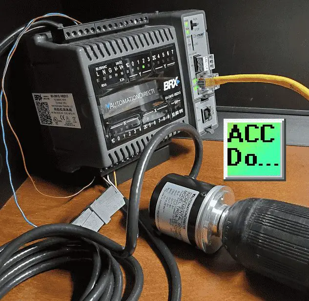
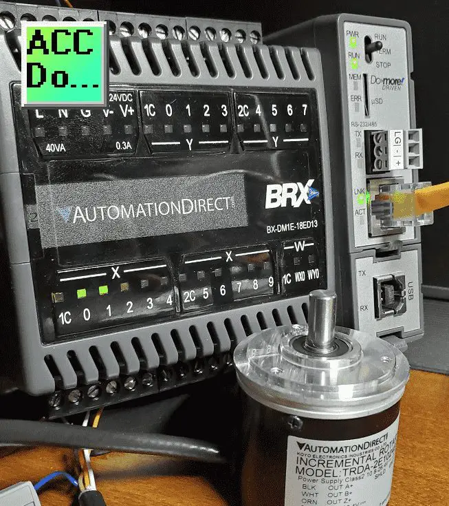
Wiring of the Incremental Encoder to the BRX Do-More PLC
We are using the TRDA-2E series of encoders. The one that we have connected is an open collector NPN sinking output. It has 1024 pulses per revolution.
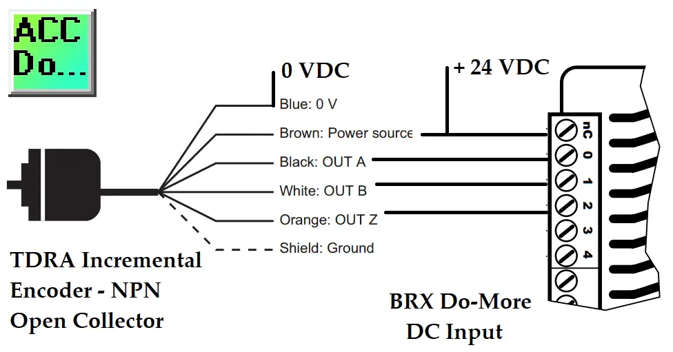 Previously we looked at the wiring of the A, B, and Z phases of the encoder. The sinking output of the encoder means a sourcing input to the BRX Do-More PLC.
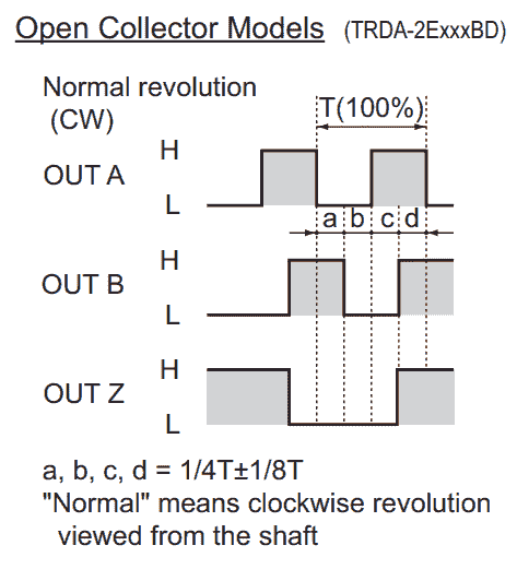 Incremental encoders Z phase will have a single pulse that is the same on time as the A and B phases. This outputs once per one full revolution of the encoder.
BRX Do-More PLC High-Speed Input Pulse Catch Programming
We will now configure the high-speed input pulse catch.
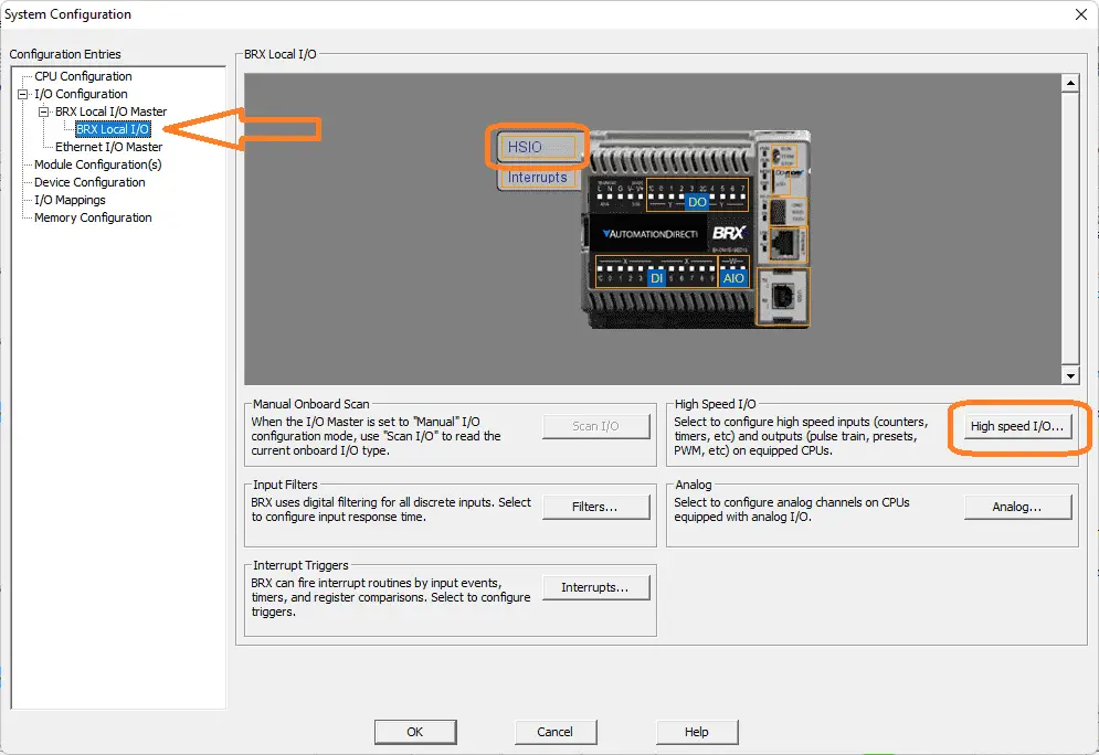 Call up the system configuration window by selecting it under tools in the project browser or the icon on the main menu. You can also use the main menu | PLC | System Configuration…
On the left-hand side of the system configuration window, select BRX Local I/O. We can now select the HSIO from the picture when you move your mouse over it or the High-Speed I/O button.
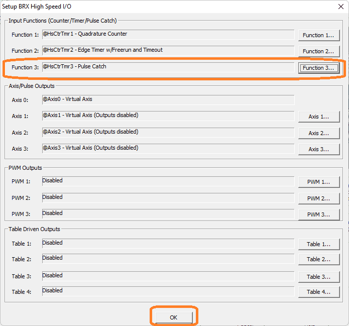
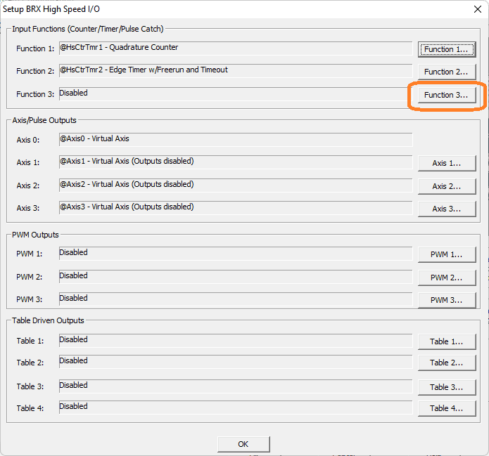 This will display the Setup BRX High-Speed I/O window. You can see that we have functions 1 and 2 already programmed from last time. Select the Function 3… button.
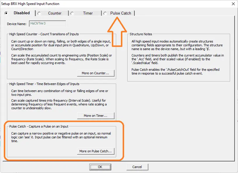 The default is to have the function disabled. You will see that the default device name is HsCtrTmr3. This sets up the structure for the high-speed input function 3. A description of the three different modes is shown. Select the Pulse Catch tab along the top of the window.
 Device Name – Name was given to this High-Speed Pulse Catch function. This name will also be used as the name of the structure you will use to interact with this edge timer function in the ladder logic project. The device name can be 1 to 16 characters in length and consist of any combination of alphanumeric characters and underscores (‘_’, ‘a-z’, ‘A-Z’, 0-9), no spaces or punctuation marks are allowed, and must begin with a letter or an underscore.
Pulse Catch Input – This selects which of the High-Speed inputs to use.
Note: although you can select any of the onboard discrete inputs, only the first 10 inputs of properly-equipped BRX CPUs are high-speed. All of the inputs on the HSIO modules are High-Speed
– Pulse Direction – This button specifies whether to monitor the input for positive pulses or negative pulses. Clicking the button cycles through the possible selections.
– Minimum Width In – This specifies the minimum pulse width input (in microseconds) that will generate a Pulse Catch event.
– Pulse Out Width – This specifies how long the generated output (Device Name .PulseCatchOut) will be ON each time a Pulse Catch event is generated. A value of 0 means the output will be ON for one complete PLC scan. Any other positive value means the output will be ON for that number of milliseconds. The structure member.OutputTime contains the amount of time(in milliseconds) remaining for the output to be ON.
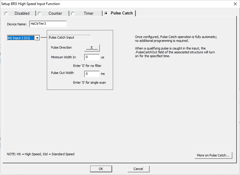 We will leave the device name as the default value. The Z phase of our encoder will be on X2 input. Using the positive pulse on the pulse direction we will leave the minimum width as 0 microseconds. Our output will be on for one PLC scan because the pulse output is left as 0 milliseconds. Select OK.
 Our BRX Do-More PLC high-speed input pulse catch is now programmed. It will operate completely automatic asynchronously. This means it is not dependent to operate based on the scan of the PLC. Select OK.
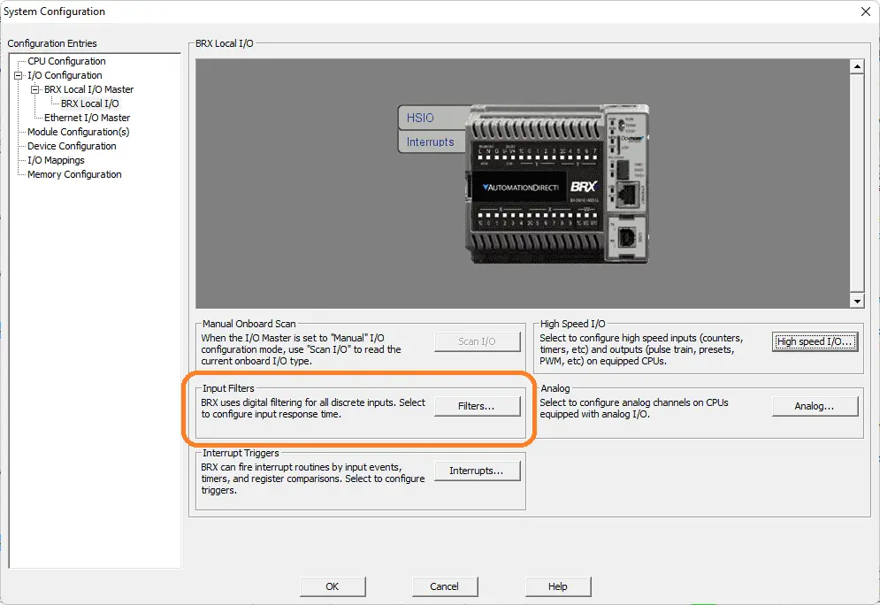 Select the filters button.
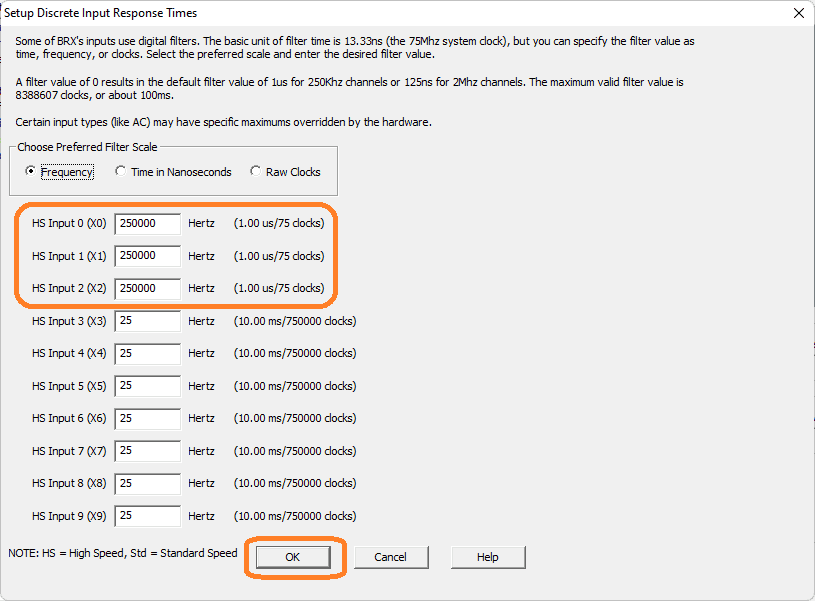 The setup discrete input response times window will allow us to ensure the first three inputs (A, B, Z phases of our incremental encoder) to 250 000 pulses per second are set. (250 kHz) Select OK.
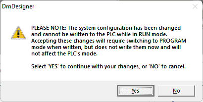 This warning indicates that we have changed the PLC system configuration. In order for this to function correctly in our BRX Do-More PLC, we must write this new configuration. Select Yes.
 In the project browser window under I/O, you will be able to see the structure for the high-speed input pulse catch that we just programmed. ($HsCtrTmr3)
BRX Do-More PLC High-Speed Input Pulse Catch Ladder Logic
Using the ladder logic developed last time for the high-speed input counter and timer, we will add new rungs.
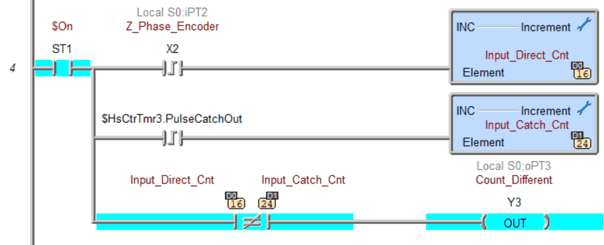 Using the leading edge of X2 (Z phase) we increment memory register D0. D1 memory register is incremented using the catch pulse of the high-speed input that we just programmed above. The two memory locations are compared for not being equal. If this is true then output Y3 is turned on.
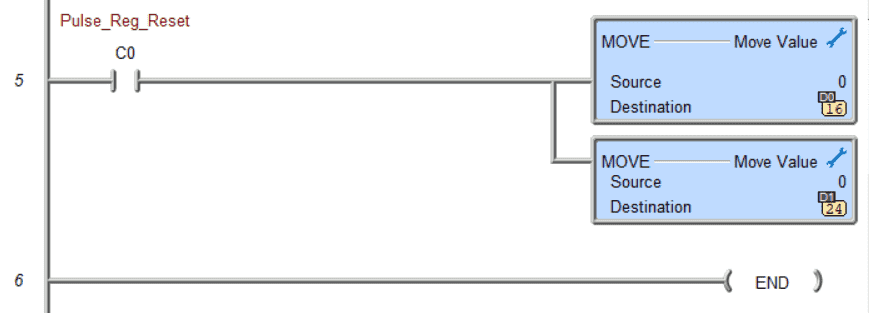 Bit C0 will reset the two memory locations back to zero.
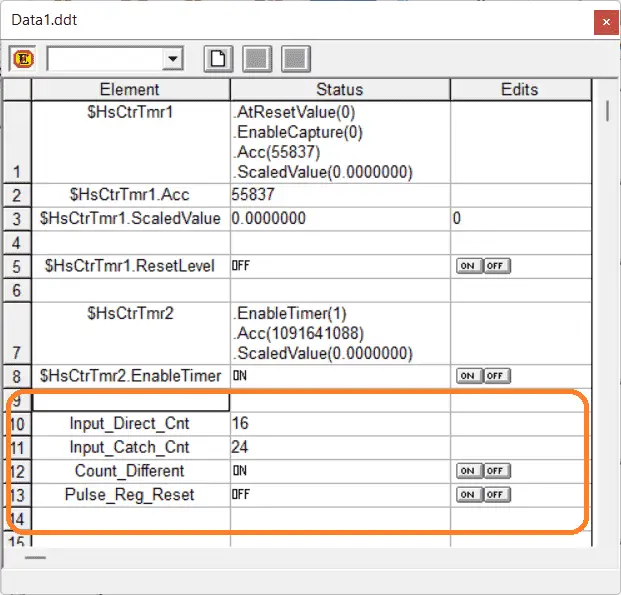 Use the data monitor to view and reset the memory locations. You will see that our high-speed input pulse catch will have a greater value because it will not miss counts due to the PLC scan time.
Watch the video below to see this high-speed input pulse catch in action on our BRX Do-More PLC.
BRX Do-More PLC Scan Time Monitor
The scan time of the BRX Do-More PLC can be viewed from the system information window. Scan time is the time that it takes to read inputs, solve logic, set outputs, and perform communication and self-diagnostics in the PLC.
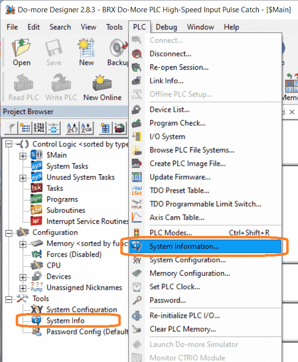 Select System Information under tools in the project browser or by the main menu | PLC | System Information…
 You can also see the system information by selecting the Info icon on the main menu.
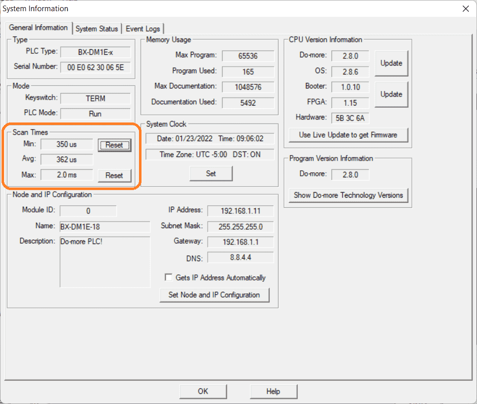 Under the heading of scan times the minimum, average, and maximum times are displayed. These can be reset by selecting the appropriate button.
The input on X2 will have to be on for at least the duration of the scan time if it is to be seen with the ladder logic alone.
 Watch the video below to see this high-speed input pulse catch and scan time in action on our BRX Do-More PLC. The encoder is turned by a drill to generate the pulse input on X2.
Download the BRX Do-More program here.
BRX Series PLC from Automation Direct – Power to deliver
Overview Link (Configure and purchase a system)
Manuals and Product Inserts (Installation and Setup Instruction)
Do-More Designer Software (Free Download Link) – The software will contain all of the instruction sets and help files for the BRX Series PLC.
Watch on YouTube: BRX Do-More PLC High-Speed Input Pulse Catch
If you have any questions or need further information please contact me.
Thank you,
Garry
If you’re like most of my readers, you’re committed to learning about technology. Numbering systems used in PLCs are not difficult to learn and understand. We will walk through the numbering systems used in PLCs. This includes Bits, Decimal, Hexadecimal, ASCII, and Floating Point. To get this free article, subscribe to my free email newsletter.
Use the information to inform other people how numbering systems work. Sign up now. The ‘Robust Data Logging for Free’ eBook is also available as a free download. The link is included when you subscribe to ACC Automation.