The productivity open Arduino P1AM I/O interface chip-set supports the full suite of Productivity 1000 (P1) Inputs / Outputs expansion modules. These modules are industry approved and proven in the industrial environment. Modern industrial signal levels for digital and analog inputs and outputs are used.
P1000 modules available to you include the following:
• Discrete (Digital)
• Analog
• Temperature
• Relay (Digital)
• High-speed Input
• PWM
We will be adding additional discrete input and output modules (cards) to our P1AM-START1 ProductivityOpen starter kit with Ethernet. A program will then be discussed that will print the modules in our system and then set and reset discrete digital inputs and outputs.
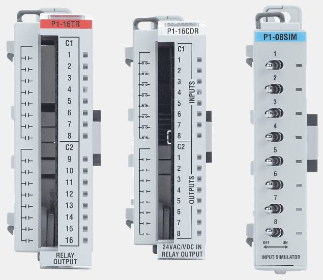
P1-16TR – Productivity1000 relay output module, 16-point, 6-24 VDC/6-120 VAC, (16) Form A (SPST) no-suppression, 2 isolated common(s), 8 point(s) per common, 2A/point, 8A/common.
P1-16CDR – Productivity1000 discrete combo module, Input: 8-point, 24 VAC/VDC, sinking/sourcing, Output: 8-point, 6-24 VDC/6-120 VAC, relay, (8) Form A (SPST) relays, 1A/point.
P1-08SIM – Productivity1000 simulator input module, 8-point.
Let’s get started.
Previous posts in this Productivity Open Arduino Compatible Industrial Controller Series
A full list can be obtained at the following location:
Productivity Open (P1AM-100) Arduino Controller
Productivity Open Arduino Controller Hardware
– Starter Kit Unboxing Video
– Powering Up Video
Installing the Software – Video
First Program – Video
Program Structure – Video
Variables Data Types – Video
Serial Monitor COM – Video
Program Control – Video
Operators – Video
GPIO Inputs and Outputs – Video
Math Instructions – Video
Time Instructions – Video
P1000 Expansion Analog Combination Module – Video
Watch the video below to see the program (sketch) using the P1000 discrete input and output modules on our productivity open industrial Arduino controller.
Arduino P1AM CPU Base LED
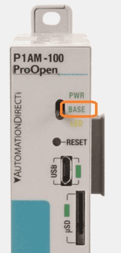
When this LED is on it indicates the Base Controller is powered and has been initialized by calling P1.init().
Note: External 24V or a P1000 Series power supply must be used for the Base Controller and modules to be powered.
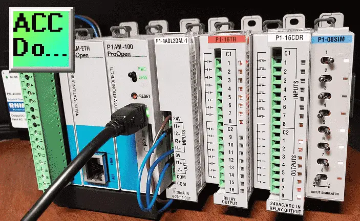
Discrete Digital Input / Output Cards
The following discrete digital inputs and outputs modules (cards) will be added to our Arduino P1AM-START1 ProductivityOpen starter kit with Ethernet.
Additional information on wiring can be obtained by the links below each module.
P1-16TR – Productivity1000 relay output module, 16-point, 6-24 VDC/6-120 VAC, (16) Form A (SPST) no-suppression, 2 isolated common(s), 8 point(s) per common, 2A/point, 8A/common.
Note: Requires removable terminal block or ZIPLink pre-wired cables
Data Sheet
P1-16TR on AutomationDirect.com
P1-16CDR – Productivity1000 discrete combo module, Input: 8-point, 24 VAC/VDC, sinking/sourcing, Output: 8-point, 6-24 VDC/6-120 VAC, relay, (8) Form A (SPST) relays, 1A/point.
Note: Requires removable terminal block or ZIPLink pre-wired cables
Data Sheet
P1-16CDR on AutomationDirect.com
P1-08SIM – Productivity1000 simulator input module, 8-point.
Data Sheet
P1-08SIM on AutomationDirect.com
I/O Card Addressing (Reference)
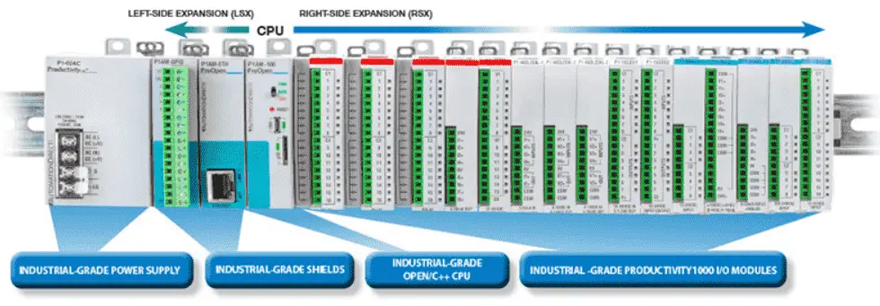
The P1000 modules are addressed or referenced by their position to the right-hand side of the P1AM CPU unit. We can add up to 15 cards (modules) to our CPU unit.
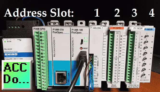
You can see that each of the cards will be numbered from 1 to 15 starting with the closest to the CPU unit being slot number 1. Each digital card may have discrete input and outputs called points. So we can address the individual input or output by the slot and point associated with it.
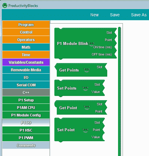
Arduino ProductivityBlocks P1 Inputs / Outputs Instructions
Under the P1 I/O heading in productivity blocks, we can select several instructions related to discrete inputs and outputs.
P1 Module Blink – Digital Outputs
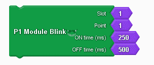
This will create a basic program that blinks the digital output of a P1 discrete output module. Select the module’s ‘Slot’ and the desired output ‘Point’ to blink. The ‘ON time’ and ‘OFF time’ give the duration that the output will remain on/off.
Note: This instruction uses the delay instruction so it is good to quickly test output but be careful when using it in your programs.
Time Instructions – Video
Get Points (Inputs) / Set Points (Outputs)
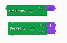
The get points is used to simultaneously retrieve all input points from a P1 digital input module. The input points are all packed into the binary digits of an integer. Use the ‘Slot’ to select which P1 digital input module to retrieve input data from. The output of the ‘Get Points’ block is an integer whose binary digits are the values of the input points (starting with point 1).
The set points is used to simultaneously set all output points on a P1 digital output module. The desired set values of the points are contained in the binary digits of an integer. Use the ‘Slot’ to select which P1 digital output module to set. The ‘Value’ is an integer whose binary digits will be written (in order) to the output points of the desired P1 digital output module.
Get Point (Inputs) / Set Point (Outputs)
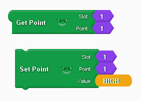
The get point is used to retrieve the state of an input point on a P1 digital input module. Use the ‘Slot’ to select which P1 digital input module to retrieve input data. The ‘Point’ selects which point to read from the P1 digital input module. (Boolean)
The set point is used to set the state of an output point on a P1 digital output module. Use the ‘Slot’ to select which P1 digital output module to set. The ‘Point’ is the desired output point of the P1 digital output module. The selected output point is set to the value of ‘Value’ (Boolean).
ProductivityBlocks Print Modules Instructions
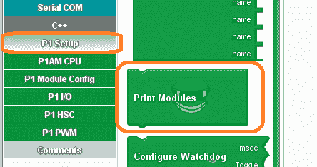
Under the P1 Setup menu on productivity blocks, we have the print modules instruction. This will print out digital inputs and outputs on our Arduino P1AM unit.
This instruction will print the modules discovered during the P1 module initialization to the Serial Monitor.
Serial Monitor COM – Video
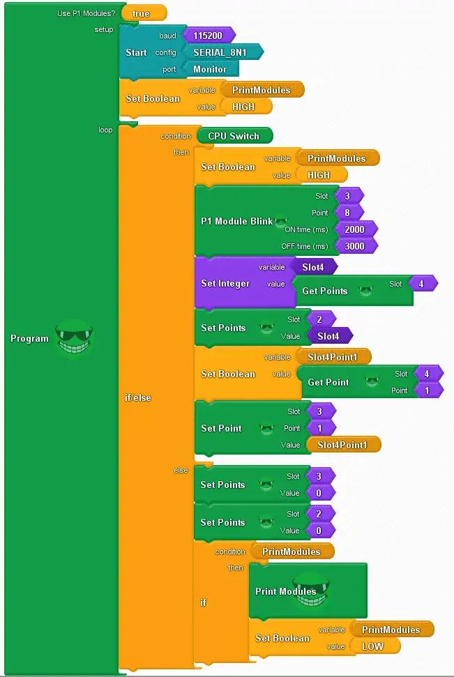
Arduino P1AM Expansion P1 Inputs and Outputs Sample Program
Our sample program (sketch) will see if the switch on the CPU is on. If it is then it will then blink slot 3 point 8 using the P1 Module Blink instruction. We will then get all of the points from slot 4 (Input Simulator) and set the output points to slot 2. (P1-16TR) Get Point is then used to read the first input on the simulator. (Slot 4 Point 1) This information is then used to Set Point slot 3 point 1.
If the switch is off then we will print the P1000 modules connected out the serial monitor port and all of the output P1000 modules will be turned off.
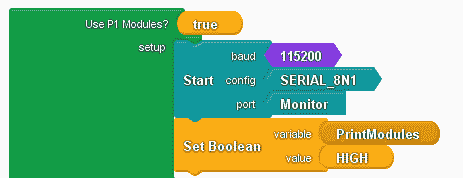
The use of P1 Modules is set to true. This will put in the library for the P1AM and P1_HSC. This allows our Arduino digital inputs and outputs to function correctly. The monitor will be configured using 115200 baud, 8N1. We will also set a Boolean variable (PrintModules) (on/off) to High.
#include
#include
/******************************************************************************************
* Automationdirect.com
* This version of ProductivityBlocks supports P1AM-100 Library V1.0.0
* To download this library, please visit https://github.com/facts-engineering/P1AM
* For information on the P1AM-100 hardware, please visit https://www.automationdirect.com
******************************************************************************************/
bool _PBVAR_1_PrintModules= false ;
boolean __proBlocksDigitalRead(int pinNumber)
{
pinMode(pinNumber, INPUT);
return digitalRead(pinNumber);
}
int _PBVAR_2_Slot4 = 0 ;
bool _PBVAR_3_Slot4Point1= false ;
void setup()
{
Serial.begin(115200);
while(!P1.init())
{
}
Serial.begin(115200, SERIAL_8N1);
_PBVAR_1_PrintModules = HIGH ;
}
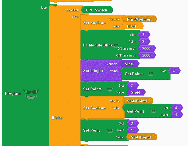
We will use an if/else instruction with the condition for the CPU switch. When it is on the boolean one-shot variable (PrintModules) is set to High. (reset) The P1 Module Blink will turn on slot 3 point 8 for 2000 milliseconds (2 sec) and off for 3000 milliseconds (3 sec). This is on our Arduino digital output P1 card. The set integer variable (Slot4) will contain all of the points in slot 4 which is the input simulator. All of the points in slot 2 are then set using the information from slot 4.
We then read a single input point in slot 4 point 1. This information is then used to set a single output at slot 3 point 1.
void loop()
{
if (__proBlocksDigitalRead(31))
{
_PBVAR_1_PrintModules = HIGH ;
P1.writeDiscrete(HIGH, 3, 8);
delay(2000);
P1.writeDiscrete(LOW, 3, 8);
delay(3000);
_PBVAR_2_Slot4 = P1.readDiscrete(4, 0) ;
P1.writeDiscrete(_PBVAR_2_Slot4, 2, 0);
_PBVAR_3_Slot4Point1 = bitRead(P1.readDiscrete(4, 0),1-1) ;
P1.writeDiscrete( (uint32_t)_PBVAR_3_Slot4Point1, 3, 1);
}
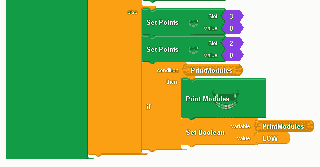
When the CPU switch is off then we will set the output slots 3 and 2 to 0. This will turn off all of the digital outputs.
If our PrintModules variable is high then we will trigger the Print Modules command and then set this one-shot variable to low.
else
{
P1.writeDiscrete(0, 3, 0);
P1.writeDiscrete(0, 2, 0);
if (_PBVAR_1_PrintModules)
{
P1.printModules();
_PBVAR_1_PrintModules = LOW ;
}
}
}
Our program is complete. Click the verify button in productivity blocks to compile and translate our program to the C++ code for our Arduino P1AM-100 CPU.
Note: You can also choose upload in productivity blocks to automatically compile and upload in one step.
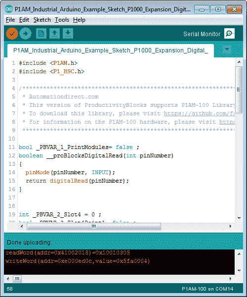
Once the Arduino software (IDE – integrated development environment) is finished compiling, select the upload button to send the program to our P1AM CPU.

Once the upload to the P1AM CPU is complete, we can select a serial monitor.
When the CPU switch is on will see our blink, set/read point, and set/read points working with our discrete input and output modules.
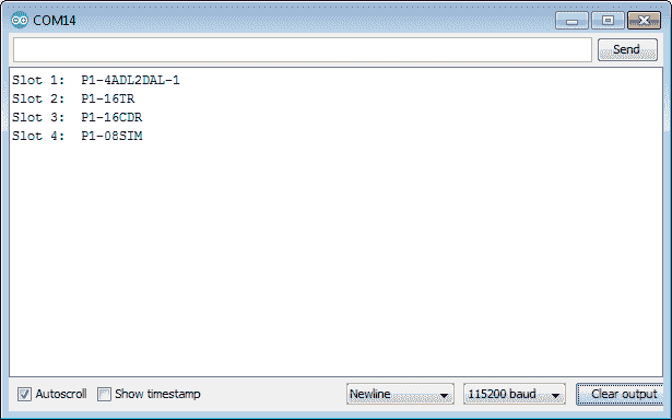
When the CPU switch is off the modules connected will be displayed on the serial monitor. The outputs will be turned off.
Watch the video below to see the operation of our sample time program with the productivity open industrial Arduino controller.
Download the P1AM-100 sample sketch and Productivity Block program here.
Productivity Open Arduino Compatible Links:
Product Hardware
– Productivity Open (Automation Direct)
– P1AM-100 Specifications
– Productivity Open User Manual
– Configure a Productivity Open Arduino-based Controller
– Open Source Controllers (Arduino-Compatible)
– Productivity Open Documentation (Facts Engineering)
– P1AM Design Files
Software
– Arduino IDE (Integrated Development Environment)
– P1AM-100 library (Easy Interface for controlling P1000 Modules)
– Productivity Blocks (Development Timesaver)
– Productivity Blocks Documentation (Wiki)
Community
– Automation Direct Forum – Open Source Devices
Next time we will continue looking at the P1000 Expansion Digital Inputs and Outputs in part 2 on our P1AM-100 Arduino Industrial Controller.
Watch on YouTube: Productivity Open P1AM Industrial Arduino P1000 Expansion Digital Inputs and Outputs Part 1
If you have any questions or need further information please contact me.
Thank you, Garry
If you’re like most of my readers, you’re committed to learning about technology. Numbering systems used in PLC’s are not difficult to learn and understand. We will walk through the numbering systems used in PLCs. This includes Bits, Decimal, Hexadecimal, ASCII and Floating Point. To get this free article, subscribe to my free email newsletter.

The ‘Robust Data Logging for Free’ eBook is also available as a free download. The link is included when you subscribe to ACC Automation.