
We will now look at the Arduino thermocouple module. The productivity open P1AM industrial Arduino P1000 thermocouple module can be connected to our P1AM-START1 ProductivityOpen starter kit with Ethernet. We will program our Arduino thermocouple module using the configuration tool on GitHub and the productivity blocks.
The productivity open P1AM I/O interface chip-set supports the full suite of Productivity 1000 I/O expansion modules. These modules are industry-approved and proven in the industrial environment. Modern industrial signal levels are used for digital and analog inputs and outputs. P1000 modules available to you include the following:
• Discrete
• Analog
• Temperature
• Relay
• High-speed Input
• PWM
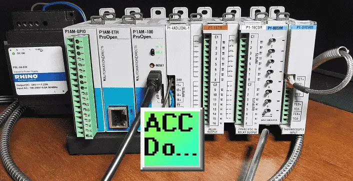
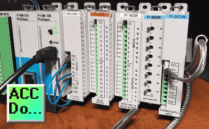
We will be adding and programming a P1-04THM thermocouple temperature and voltage input module to our P1AM-START1 ProductivityOpen starter kit with Ethernet. This card is very flexible, and we will use the configuration tool on GitHub and productivity blocks. Let’s get started.
Previous posts in this Productivity Open Arduino Compatible Industrial Controller Series
A full list can be obtained at the following location:
Productivity Open (P1AM-100) Arduino Controller
Productivity Open Arduino Controller Hardware
– Starter Kit Unboxing Video
– Powering Up Video
Installing the Software – Video
First Program – Video
Program Structure – Video
Variables Data Types – Video
Serial Monitor COM – Video
Program Control – Video
Operators – Video
GPIO Inputs and Outputs – Video
Math Instructions – Video
Time Instructions – Video
P1000 Expansion Analog Combination Module – Video
P1000 Expansion Digital Inputs and Outputs Part 1 – Video
P1000 Expansion Digital Inputs and Outputs Part 2 – Video
Watchdog Timer – Video
Watch the video below to see the wiring and sample program (sketch) using the P1000 thermocouple temperature module on our productivity open industrial Arduino controller.
P1AM CPU Base LED
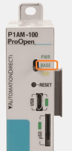
When this LED is on it indicates the Base Controller is powered and has been initialized by calling P1.init().
Note: External 24V or a P1000 Series power supply must be used for the Base Controller and modules to be powered.
P1-04THM – Thermocouple Temperature and Voltage Input
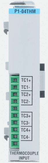
The P1-04THM Thermocouple Input Module provides four differential channels for receiving thermocouple and voltage input signals.
Data Sheet
P1-04THM on AutomationDirect.com
Thermocouple Input Ranges:
Type J -190° to 760°C (-310° to 1400°F)
Type E – 210° to 1000°C (-346° to 1832°F)
Type K -150° to 1372°C (-238° to 2505°F)
Type R 65° to 1768°C (149° to 3214°F)
Type S 65° to 1768°C (149° to 3214°F)
Type T -230° to 400°C (-382° to 752°F)
Type B 529° to 1820°C (984° to 3308°F)
Type N -70° to 1300°C (-94° to 2372°F)
Type C 65° to 2320°C (149° to 4208°F)
mV Device Input Ranges:
0–39.0625 mVDC,
±39.0625 mVDC,
±78.125 mVDC,
0–156.25 mVDC,
±156.25 mVDC,
0–1250 mVDC
P1-04THM Schematic
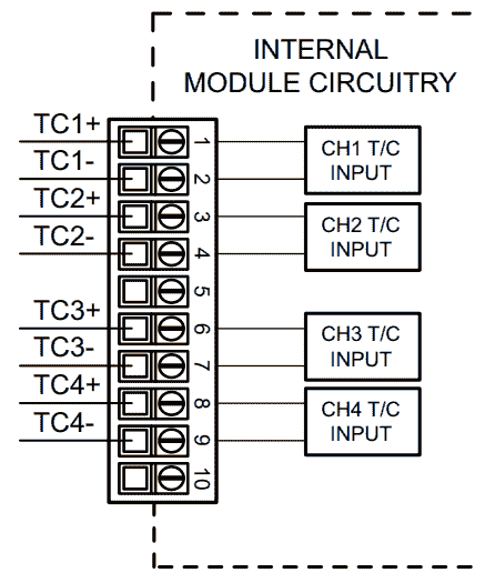
Wiring Diagrams
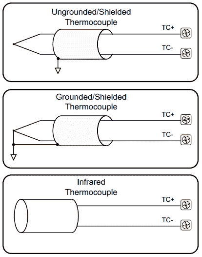
Thermocouple Input Circuits
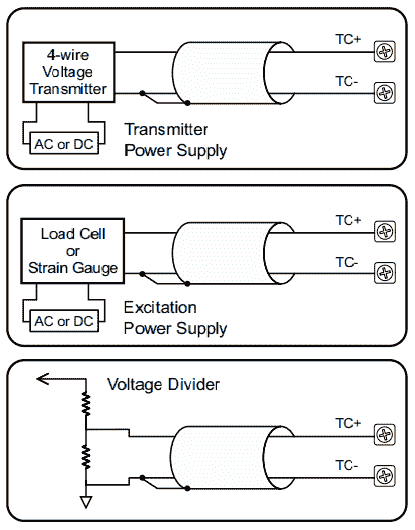
Voltage Input Circuits
Notes:
1. Connect the shield to the thermocouple signal/ground only. Do not connect to both ends.
2. Install jumper wire on each unused input, TC+ to TC-.
3. With grounded thermocouples, take precautions to prevent having a voltage potential between thermocouple tips. A voltage of 1.25V or greater between tips will skew measurements.
4. Use shielded, twisted thermocouple extension wire that matches the thermocouple type. Use thermocouple-compatible junction blocks.
P1-04THM Configuration C++
The P1-04THM configuration is located here.
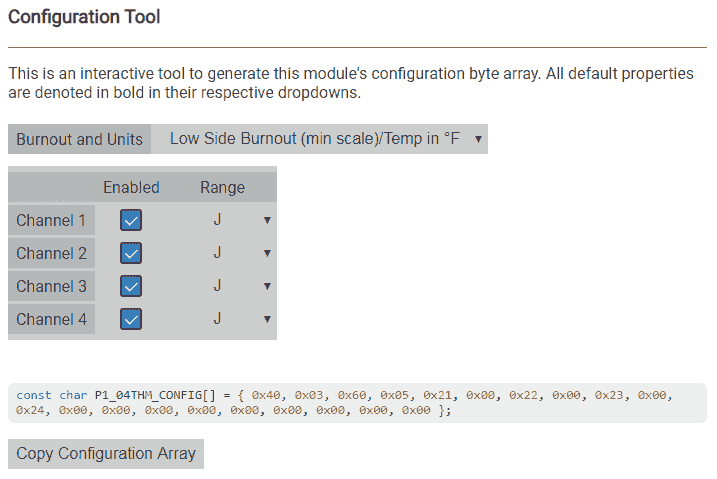
We will configure this for low side burnout (min scale)/Temp in C. (Celsius)
Channel 1 will be enabled. You have to select the channels in order from 1 to 4 and 4 to 1 to disable the channel.
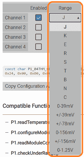
We will be using the J type thermocouple input, but you can select the arrow to the right of the range for any of the thermocouple or voltage input selection.
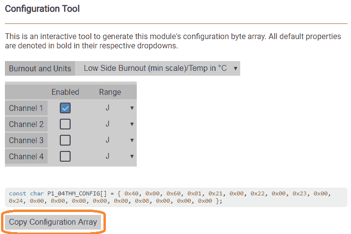
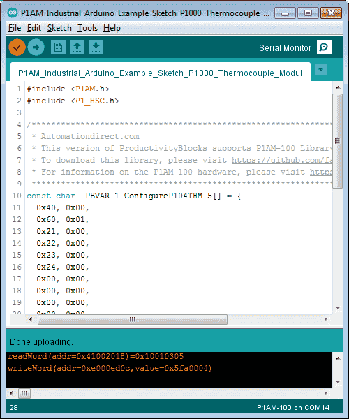
Here is our configuration in C++ for the thermocouple module.
const char P1_04THM_CONFIG[] = { 0x40, 0x00, 0x60, 0x01, 0x21, 0x00, 0x22, 0x00, 0x23, 0x00, 0x24, 0x00, 0x00, 0x00, 0x00, 0x00, 0x00, 0x00, 0x00, 0x00 };
Select copy configuration array to copy to the Windows clipboard. This then can be pasted into the Arduino IDE.
P1-04THM Configuration ProductivityBlocks
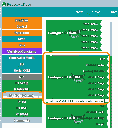
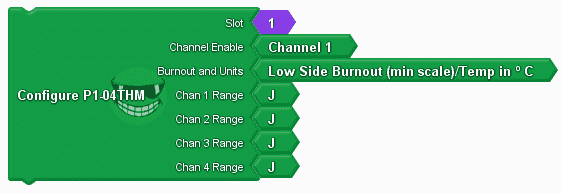
Call up productivity blocks from the arduino IDE. Main Menu | Tools | ProductivityBlocks. Select the configure P1-04THM block.
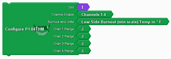
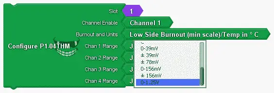
We will select the same settings as described above. Channel 1 only with a J type thermocouple. If you select the tag with your mouse you will then see an arrow to the right-hand side that will allow you to select different options.
Here is our completed configuration.
P1-04THM Sample Program (Sketch)
Our sample program (sketch) will set up the P1-04THM card and print the current temperature every second on the serial monitor.
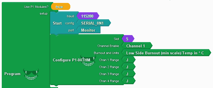
The use of P1 Modules is set to true. This will include the library for the P1AM and P1_HSC.
We use the configure P1-04THM as described above. Slot 5 is used because this is the fifth P1000 expansion module attached.
#include
#include
/******************************************************************************************
* Automationdirect.com
* This version of ProductivityBlocks supports P1AM-100 Library V1.0.0
* To download this library, please visit https://github.com/facts-engineering/P1AM
* For information on the P1AM-100 hardware, please visit https://www.automationdirect.com
*****************************************************************************************/
const char _PBVAR_1_ConfigureP104THM_5[] = {
0x40, 0x00,
0x60, 0x01,
0x21, 0x00,
0x22, 0x00,
0x23, 0x00,
0x24, 0x00,
0x00, 0x00,
0x00, 0x00,
0x00, 0x00,
0x00, 0x00
};
double _PBVAR_2_Double_Variable = 0.0 ;
void setup()
{
while(!P1.init())
{
}
Serial.begin(115200, SERIAL_8N1);
P1.configureModule(_PBVAR_1_ConfigureP104THM_5, 5);
}
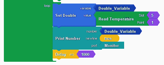
We set the double variable because this will allow us to use the range of the J type thermocouple unit we are using and the accuracy. (Two decimal places.) (-190° to 760°C) Using the read temperature block we set our double variable.
Note: Even if we are using a voltage input signal on this card, we would still use the read temperature block.
The temperature reading (double variable) is then printed to the serial monitor port. Our example then delays one second (1000 ms) and then loops again.
void loop()
{
_PBVAR_2_Double_Variable = P1.readTemperature(5, 1) ;
Serial.println(_PBVAR_2_Double_Variable);
delay( 1000 );
}
Here is the entire program.
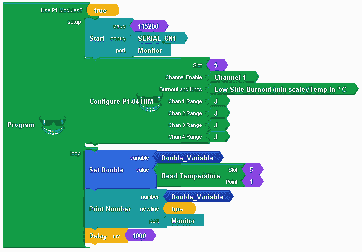
Once the upload to the P1AM CPU is complete, we can test our program.
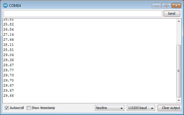
Calling up the serial monitor, we can see our current temperature in degrees Celsius being updated on our monitor every second.
Watch the video below to see the operation of our sample sketch with the temperature module in the productivity open industrial arduino controller.
Download the P1AM-100 sample sketch and Productivity Block program here.
Productivity Open Arduino Compatible Links:
Product Hardware
– Productivity Open (Automation Direct)
– P1AM-100 Specifications
– Productivity Open User Manual
– Configure a Productivity Open Arduino-based Controller
– Open Source Controllers (Arduino-Compatible)
– Productivity Open Documentation (Facts Engineering)
– P1AM Design Files
Software
– Arduino IDE (Integrated Development Environment)
– P1AM-100 library (Easy Interface for controlling P1000 Modules)
– Productivity Blocks (Development Timesaver)
– Productivity Blocks Documentation (Wiki)
Community
– Automation Direct Forum – Open Source Devices
Next time we will utilize PID with our P1-04THM module on our P1AM-100 Arduino Industrial Controller to control a cup of water. The heater will be controlled by a relay output.
Watch on YouTube: Productivity Open P1AM Industrial Arduino P1000 Expansion Thermocouple Module https://youtu.be/ONme9l2HK34
If you have any questions or need further information please contact me.
Thank you, Garry
If you’re like most of my readers, you’re committed to learning about technology. Numbering systems used in PLC’s are not difficult to learn and understand. We will walk through the numbering systems used in PLCs. This includes Bits, Decimal, Hexadecimal, ASCII and Floating Point. To get this free article, subscribe to my free email newsletter.

The ‘Robust Data Logging for Free’ eBook is also available as a free download. The link is included when you subscribe to ACC Automation.