
A watchdog is a piece of code that will time out when an error occurs in our program. It will usually cause the CPU (program/sketch) to stop or reset.

We will now look at the instructions for the watchdog timer in productivity blocks. This includes the Configure Watchdog, Start Watchdog, Stop Watchdog, and Pet Watchdog.
Our sample sketch will modify the P1000 Expansion Digital Inputs and Outputs Part 2 program by adding a watchdog timer.
Let’s get started.
Previous posts in this Productivity Open Arduino Compatible Industrial Controller Series
A full list can be obtained at the following location:
Productivity Open (P1AM-100) Arduino Controller
Productivity Open Arduino Controller Hardware
– Starter Kit Unboxing Video
– Powering Up Video
Installing the Software – Video
First Program – Video
Program Structure – Video
Variables Data Types – Video
Serial Monitor COM – Video
Program Control – Video
Operators – Video
GPIO Inputs and Outputs – Video
Math Instructions – Video
Time Instructions – Video
P1000 Expansion Analog Combination Module – Video
P1000 Expansion Digital Inputs and Outputs Part 1 – Video
P1000 Expansion Digital Inputs and Outputs Part 2 – Video
Watch the video below to see the watchdog timer in our sample program (sketch) on our productivity open industrial Arduino controller.
P1AM Arduino Setup – Watchdog Timer
A watchdog timer is a method to determine if something has gone wrong in your program. This will allow you to stop or reset the CPU. During the normal execution of your program, the watchdog gets reset. This prevents the watchdog timer from expiring or timing out.
We have four different productivity block instructions dealing with the watchdog timer.
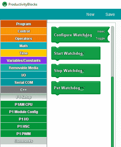
These instructions are under the P1 Setup menu option.
Configure Watchdog Timer

The configure watchdog will set the watchdog mode and the number of milliseconds before the watchdog times out.
The ‘msec’ socket sets the number of milliseconds before watchdog timeout. The value of ‘Toggle’ sets the mode of the watchdog feature:
false – watchdog timeout will stop CPU until the power cycle.
true – watchdog timeout will reset the CPU.
Start Watchdog

Once the watchdog has been configured using the ‘Configure Watchdog’ block, the watchdog timer can be started.
Stop Watchdog

Once the watchdog timer has been started, the watchdog timer can be stopped.
Pet Watchdog

Pet the watchdog means to reset the watchdog timer. If the “watchdog” is not “pet” before the timer reached the timeout time, the watchdog will trigger and reset/halt the P1AM-CPU depending on the setting given by the ‘Configure Watchdog’ block.
P1AM Arduino Expansion P1000 IO Sample Program with Watchdog Timer
The sample program is based upon the previous post on the P1AM Expansion P1000 IO. We will incorporate the watchdog timer into the program. Here is how the program will operate.
Our sample program (sketch) will see if the switch on the CPU is on. The CPU LED will be on if the program is running and off to indicate the outputs are all off. Every scan of the program will check to see if the digital input and output cards are still connected in the order that we have attached them. If they are not then the CPU LED will continually blink (flash) and all of the outputs will remain off.
When the program is running we will make a simple start-stop circuit. We have added switch 3 when turned on will enable the P1 Module Blink instruction. This instruction uses a delay that will then trigger our watchdog timer.
A shift register is used to turn on an output on the P1-16TR (16 relay output card) in sequence. Point 1 to 16 and then 16 to 1 at 500-millisecond increments.
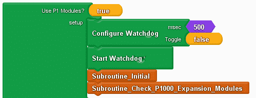
The use of P1 Modules is set to true. This will include the library for the P1AM and P1_HSC.
We used the configure watchdog instruction to setup our watchdog for 500 milliseconds. If the watchdog timer expires then the ‘False” means to stop the CPU from running. This will then turn off the outputs on our attached cards.
We then set up the subroutines that will be called.
Subroutine_Initial will turn off our outputs and initialize our timing variable for the shift register.
Subroutine_Check_P1000_Expansion_Modules will check to ensure that the digital cards are still attached and functioning correctly.
#include
#include
/******************************************************************************************
* Automationdirect.com
* This version of ProductivityBlocks supports P1AM-100 Library V1.0.0
* To download this library, please visit https://github.com/facts-engineering/P1AM
* For information on the P1AM-100 hardware, please visit https://www.automationdirect.com
*****************************************************************************************/
const char* _PBVAR_5_RollCall[] = {
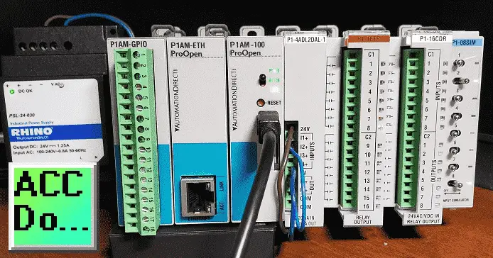
"P1-4ADL2DAL-1", "P1-16TR", "P1-16CDR", "P1-08SIM", "P1-", "P1-", "P1-", "P1-", "P1-", "P1-", "P1-", "P1-", "P1-", "P1-", "P1-"};
#define _PBVAR_6_CPU_LED_PIN 32
boolean __proBlocksDigitalRead(int pinNumber)
{
pinMode(pinNumber, INPUT);
return digitalRead(pinNumber);
}
void __proBlocksDigitalWrite(int pinNumber, boolean status)
{
pinMode(pinNumber, OUTPUT);
digitalWrite(pinNumber, status);
}
unsigned long _PBVAR_1_Slot4 = 0UL ;
int _PBVAR_2_Shift_Register = 0 ;
bool _PBVAR_3_Shift_Left= false ;
int _PBVAR_4_previousMillisecond = 0 ;
void Subroutine_Initial();
void Subroutine_Check_P1000_Expansion_Modules();
void setup()
{
while(!P1.init())
{
}
P1.configWD(500, (int)false);
P1.startWD();
Subroutine_Initial();
Subroutine_Check_P1000_Expansion_Modules();
}
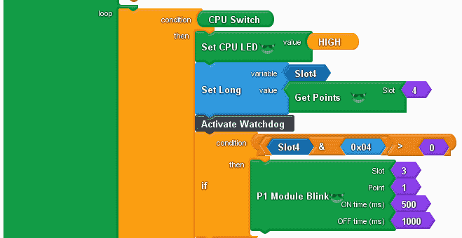
We use an if/else condition of the CPU switch. If on then we turn on the CPU LED and then set a long variable (Slot4) with the value from the get points instruction. This will tell us the position of each switch on our input simulator.
The If statement is used to look for switch 3 on slot 4. If it is greater then 0 (on) then use the P1 Module Blink instruction. Since this instruction uses a delay instruction, it will stop the CPU for 500 milliseconds to turn on the output and 1000 milliseconds to turn off the output. This will cause the watchdog timer to expire, stopping the CPU from executing our code.
void loop()
{
if (__proBlocksDigitalRead(31))
{
__proBlocksDigitalWrite(32, HIGH);
_PBVAR_1_Slot4 = P1.readDiscrete(4, 0) ;

//Activate Watchdog
if (( ( (_PBVAR_1_Slot4 & 0x04UL) ) > ( 0 ) ))
{
P1.writeDiscrete(HIGH, 3, 1);
delay(500);
P1.writeDiscrete(LOW, 3, 1);
delay(1000);
}

This is the simple start-stop circuit of our program. Slot 4 point 1 is our start and slot 4 point 2 is our stop. We use the AND instruction with the slot4 variable to determine the status of each of the inputs. When input 1 and input 2 are on then we will set slot 3 point 2 on. (start) If slot 4 point 2 turns off then we set slot 3 point 2 off. (stop)
//Start / Stop Circuit - Switch 1 Start / Switch 2 Stop (NC)
if (( ( ( (_PBVAR_1_Slot4 & 0x01UL) ) > ( 0 ) ) && ( ( (_PBVAR_1_Slot4 & 0x02UL) ) > ( 0 ) ) ))
{
P1.writeDiscrete( (uint32_t)HIGH, 3, 2);
}
if (( ( (_PBVAR_1_Slot4 & 0x02UL) ) == ( 0 ) ))
{
P1.writeDiscrete( (uint32_t)LOW, 3, 2);
}
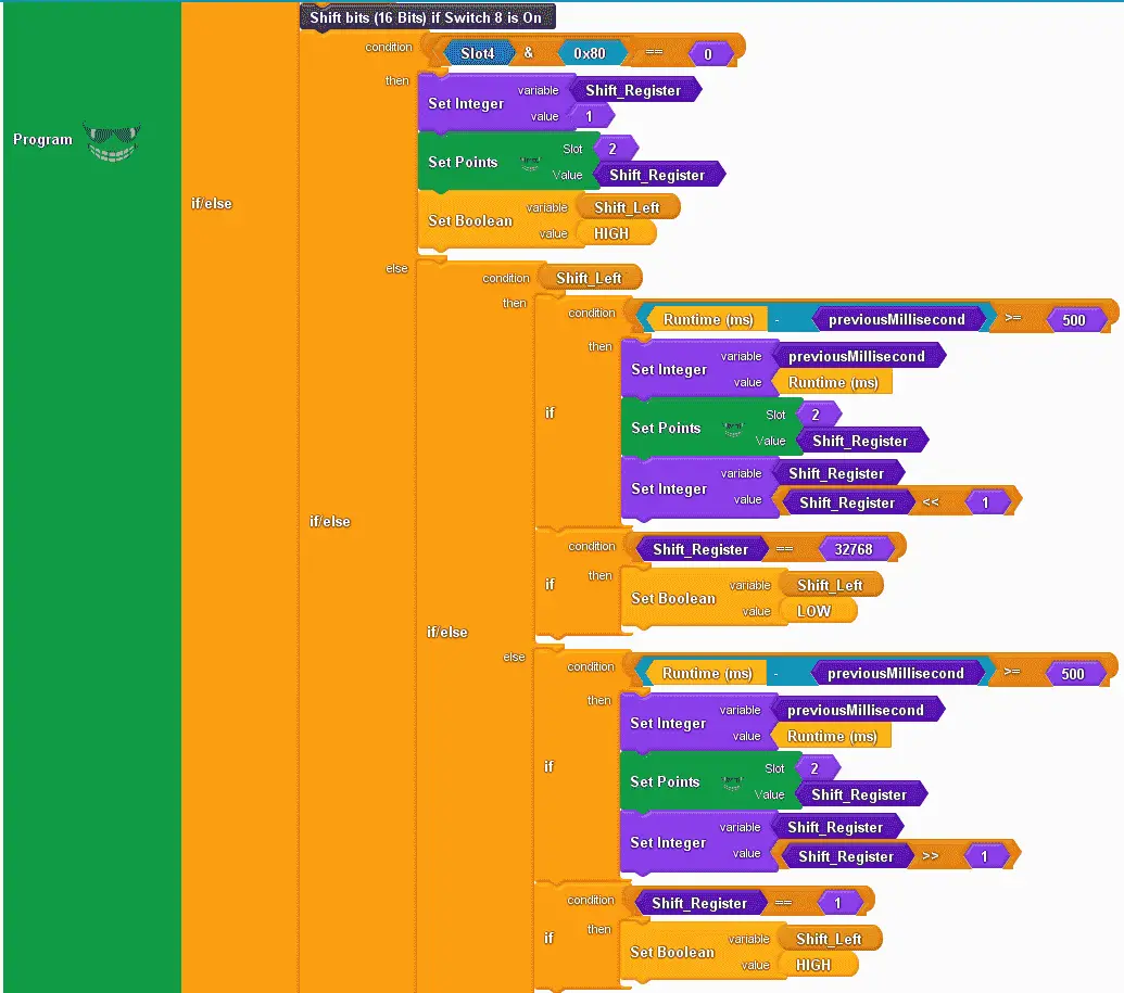
This is the shift register instruction. Using an if/else instruction we use the condition of slot 4 point 8. (0x80 = 1000 0000) If it is off, (equal to 0) then we will set the shift register variable to the value of 1. We then set slot 2 with the shift register variable. This will reset our output card. We also set a Boolean variable called shift left to high. This will keep track to see if we are shifting left or right.
When input slot 4 point 8 is on we will then use another if/else instruction. This checks for the condition of the variable shift left.
If on then we see if enough time (500 ms) has passed to shift the shift register left. We then set the output points and shift the shift register variable left by 1. We determine if the last bit of the shift register variable is on. (32768) If it is equal to this value, we then set the shift left variable to off. This will enable shifting to the right.
If off then we see if enough time (500 ms) has passed to shift the shift register right. We then set the output points and shift the shift register variable right by 1. We determine if the first bit of the shift register variable is on. (1) If it is equal to this value, we then set the shift left variable to on. This will enable shifting to the left again.
//Shift bits (16 Bits) if Switch 8 is On
if (( ( (_PBVAR_1_Slot4 & 0x80UL) ) == ( 0 ) ))
{
_PBVAR_2_Shift_Register = 1 ;
P1.writeDiscrete(_PBVAR_2_Shift_Register, 2, 0);
_PBVAR_3_Shift_Left = HIGH ;
}
else
{
if (_PBVAR_3_Shift_Left)
{
if (( ( ( millis() - _PBVAR_4_previousMillisecond ) ) >= ( 500 ) ))
{
_PBVAR_4_previousMillisecond = millis() ;
P1.writeDiscrete(_PBVAR_2_Shift_Register, 2, 0);
_PBVAR_2_Shift_Register = (_PBVAR_2_Shift_Register << 1) ;
}
if (( ( _PBVAR_2_Shift_Register ) == ( 32768 ) ))
{
_PBVAR_3_Shift_Left = LOW ;
}
}
else
{
if (( ( ( millis() - _PBVAR_4_previousMillisecond ) ) >= ( 500 ) ))
{
_PBVAR_4_previousMillisecond = millis() ;
P1.writeDiscrete(_PBVAR_2_Shift_Register, 2, 0);
_PBVAR_2_Shift_Register = (_PBVAR_2_Shift_Register >> 1) ;
}
if (( ( _PBVAR_2_Shift_Register ) == ( 1 ) ))
{
_PBVAR_3_Shift_Left = HIGH ;
}
}
}

If the CPU switch is off, we call the subroutine initial.
At the end of every loop, we will use the pet watchdog instruction and call the subroutine to check P1000 expansion modules. Petting the watchdog will reset the timer.
}
else
{
Subroutine_Initial();
}
P1.petWD();
Subroutine_Check_P1000_Expansion_Modules();
}
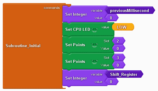
Subroutine initial will set our previous milliseconds to a value of 0, set the CPU LED low (off), and set all of the digital output points off. The shift register variable is also set to 0.
void Subroutine_Initial()
{
_PBVAR_4_previousMillisecond = 0 ;
__proBlocksDigitalWrite(32, LOW);
P1.writeDiscrete(0, 2, 0);
P1.writeDiscrete(0, 3, 0);
_PBVAR_2_Shift_Register = 0 ;
}
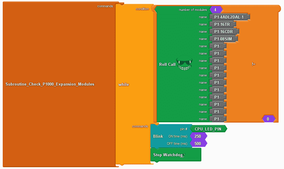
Subroutine check P1000 expansion modules will use the roll call instruction. While the roll call instruction is not equal to 0 (modules do not match) then blink the CPU LED light. We will also use the stop watchdog instruction. This will turn off the watchdog timer. Using the pet watchdog at this location would continue the execution of the program.
void Subroutine_Check_P1000_Expansion_Modules()
{
while ( ( ( P1.rollCall(_PBVAR_5_RollCall, 4) ) != ( 0 ) ) )
{
__proBlocksDigitalWrite(_PBVAR_6_CPU_LED_PIN,HIGH);
delay(250);
__proBlocksDigitalWrite(32,LOW);
delay(500);
P1.stopWD();
}
}
Once the upload to the P1AM CPU is complete, we can test our program.
When the CPU switch is on will see our start-stop circuit and shift register program working. Switch 3 will cause the watchdog timer to expire and the base LED will start to blink.
Watch the video below to see the operation of our sample sketch with a watchdog timer in the productivity open industrial Arduino controller.
Download the P1AM-100 sample sketch and Productivity Block program here.
Productivity Open Arduino Compatible Links:
Product Hardware
– Productivity Open (Automation Direct)
– P1AM-100 Specifications
– Productivity Open User Manual
– Configure a Productivity Open Arduino-based Controller
– Open Source Controllers (Arduino-Compatible)
– Productivity Open Documentation (Facts Engineering)
– P1AM Design Files
Software
– Arduino IDE (Integrated Development Environment)
– P1AM-100 library (Easy Interface for controlling P1000 Modules)
– Productivity Blocks (Development Timesaver)
– Productivity Blocks Documentation (Wiki)
Community
– Automation Direct Forum – Open Source Devices
Next time we will look at using the P1-04THM module on our P1AM-100 Arduino Industrial Controller. This is a four-point thermocouple input card.
Watch on YouTube: Productivity Open P1AM Industrial Arduino Watchdog Timer
If you have any questions or need further information please contact me.
Thank you, Garry
If you’re like most of my readers, you’re committed to learning about technology. Numbering systems used in PLC’s are not difficult to learn and understand. We will walk through the numbering systems used in PLCs. This includes Bits, Decimal, Hexadecimal, ASCII and Floating Point. To get this free article, subscribe to my free email newsletter.

The ‘Robust Data Logging for Free’ eBook is also available as a free download. The link is included when you subscribe to ACC Automation.