
AI PLC code is everywhere in the conversation right now, but does it actually work on a real machine? Instead of guessing, I set a trap. I gave both ChatGPT and Claude the exact same motor control task for the CLICK PLC — a task with a classic wiring gotcha buried in it — took exactly what each one handed back, and checked whether the AI PLC code really runs. I fully expected to catch at least one of them out. Neither took the bait. Both wrote a working program, but in two different ways. In this post, I will show you the task, what each AI produced, why both are correct, the one thing I would still add, and my honest verdict on whether AI can really program a PLC.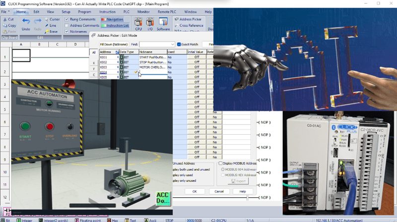
You can follow along for free. The CLICK programming software is a free download, and you can prove out the logic in a free online ladder simulator before it ever touches hardware.
This follows on from Using AI to Program a Click PLC.
If you want the ground rules I follow, see my rules for using AI in PLC programming.
New to this? Start with the PLC Beginner’s Guide.
The test I set for the AI
I wanted a task that was small enough to explain but real enough to catch a lazy answer. Here is exactly what I asked both AIs to program on the CLICK PLC:
Start and stop a motor. The start pushbutton is normally open on input X1. The stop pushbutton is wired normally closed on input X2, so X2 is ON when it is not pressed. The motor overload contact is wired normally closed on input X3, so it is ON while the motor is healthy. The motor contactor is output Y1, and a green running light is output Y2. One more twist: when I press start, I want a warning buzzer on output Y3 to sound for two seconds first, and then the motor starts.
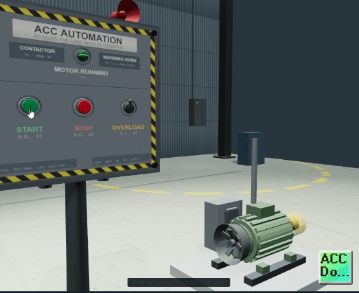
The gotcha is the normally closed wiring on the stop and overload. A lazy answer uses normally closed contacts in the ladder to match “normally closed buttons,” which is a double negative — those inputs are already ON at rest, so the motor would never start. That single detail is where I expected an AI to trip. It has a seal-in, a timer, an overload, and a small sequence on top of it. A fair test.
What ChatGPT produced
ChatGPT answered in seconds with an address list, seven rungs of ladder logic, and an explanation of each one.
CLICK PLC — MOTOR START / STOP WITH 2-SECOND PRE-START WARNING
Inputs:
X1 = START pushbutton (NO)
X2 = STOP pushbutton (NC) → ON when NOT pressed
X3 = MOTOR OVERLOAD (NC) → ON when motor is healthy
Outputs:
Y1 = Motor contactor
Y2 = Green RUN light
Y3 = Warning buzzer
Internal:
C1 = Motor start/run request
T1 = 2-second warning timer
RUNG 1 — START / RUN LATCH
X2 X3 X1
──| |─────────| |─────────| |──────────( SET C1 )
STOP OK OL OK START
RUNG 2 — STOP RESETS MOTOR REQUEST
X2
──|/|──────────────────────────────────( RST C1 )
STOP
(X2 OFF when STOP is pressed)
RUNG 3 — OVERLOAD RESETS MOTOR REQUEST
X3
──|/|──────────────────────────────────( RST C1 )
OL
(X3 OFF when overload trips)
RUNG 4 — 2-SECOND WARNING TIMER
C1
──| |──────────────────────[ T1 2.0 s ]
START REQUEST
RUNG 5 — WARNING BUZZER
C1 T1
──| |─────────|/|──────────────────────( Y3 )
REQUEST TIMER NOT DONE
BUZZER ON
RUNG 6 — MOTOR CONTACTOR
C1 T1 X2 X3
──| |─────────| |─────────| |─────────| |────( Y1 )
REQUEST DONE STOP OK OL OK
RUNG 7 — GREEN RUNNING LIGHT
Y1
──| |──────────────────────────────────( Y2 )
MOTOR ON
Its approach was a SET/RST latch. The first rung watches the start button in series with the stop and overload, and when all three are satisfied it SETs a start-request bit, C1. It then gave the stop and the overload their own separate reset rungs, each one able to RST that bit. From there it ran a two-second timer off C1, sounded the buzzer while the timer had not finished, energized the motor once it had, and turned the green light on with the motor.
The key point: it used normally open contacts for the stop and overload in the ladder, exactly right for normally closed field wiring. It did not fall for the double negative. It is correct, working AI PLC code.
What Claude produced
I gave Claude the identical prompt. It answered with an address list, five rungs, and its own explanation.
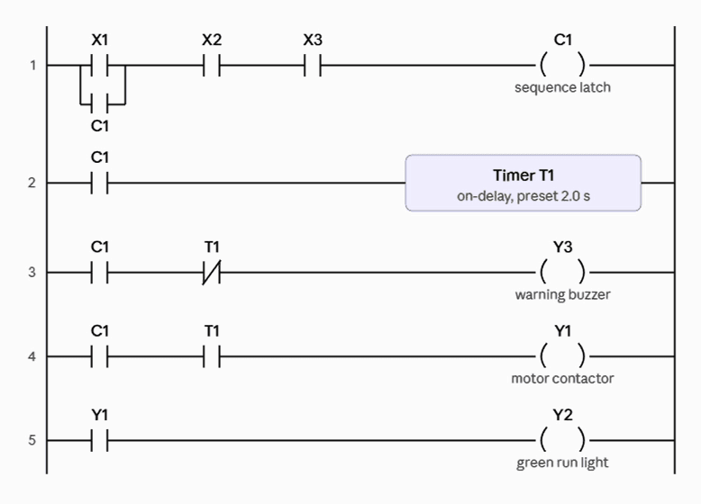
Its approach was a classic seal-in latch. Instead of splitting the logic into set and reset rungs, it put the start button in parallel with the C1 bit to form a hold, then placed the stop and overload in series so either one breaks the latch. The rest matched — a two-second timer, the buzzer while the timer runs, the motor when it finishes, and the green light with the motor.
Claude also used normally open contacts for the stop and overload, so it handled the normally closed wiring correctly too. It is also correct, working AI PLC code — just built in a different style.
Both passed the trap — here is why that matters
This is the honest headline. I designed the task to catch an AI out on the normally closed wiring, and both of them got it right. That would have been the number one mistake a beginner made too, and neither AI made it. On a clearly specified task like this one, today’s AI PLC code actually runs.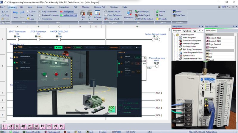
That surprised me, and I think it is worth being upfront about rather than pretending otherwise.
The interesting part — two valid styles
What I found most useful was not that they passed, but how differently they passed. ChatGPT used SET and RST; Claude used a seal-in. Both are correct, and the difference is a real lesson in PLC design.
The SET/RST version gives each stop condition its own rung. That makes it easy to see why the motor stopped and easy to add another fault later—you just add another reset rung. It costs you a few more rungs.
The seal-in version is the traditional motor-starter circuit every electrician recognizes from relay logic. It is compact; everything about the latch lives in one place, and it is instantly familiar. If you want to add another stop condition, you edit that one rung.
Neither is wrong. For a simple motor, I lean toward the seal-in because it is compact and familiar. For a machine with many stop and fault sources, the SET/RST style scales more cleanly. The fact that two AIs handed me the two textbook approaches is a nice way to teach the trade-off.
Why the AI PLC code worked — the prompt did the heavy lifting
Before anyone decides AI has this solved, here is the catch. Both pieces of AI PLC code came back correct because I told the AI exactly what it needed: the precise input and output addresses, that the stop and overload were wired normally closed and ON at rest, and the exact sequence I wanted. I gave it the same information I would give a co-worker.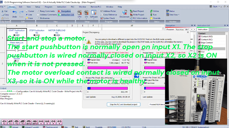
Feed an AI a vague request — “write me a motor start-stop program” — and you will get vague, generic logic that does not match your wiring and may well fall for the double negative. The skill that made this test succeed wasn’t the AI’s. It was writing a clear, specific prompt. That is the part worth practicing.
The one thing I would still add
Both pieces of AI PLC code are logically correct, but I would still change one thing on either of them, and it has nothing to do with the code. Both run the motor overload through the PLC — in a reset rung or the latch — as one of the conditions. That is fine for indication and control, but it should not be the only thing stopping the motor on a fault.
A motor overload should also be hardwired into the contactor coil circuit, so the motor drops out even if the PLC halts or an output card fails. Neither AI mentioned this, because neither AI knows how your panel is wired or what your risk is. That judgment is yours. The logic can watch the overload; the hardware must be able to stop the motor without the logic.
I still tested it before trusting it
Correct on paper is not the same as proven, so I ran it. I entered one of the AI PLC code programs in the free CLICK software, and because the CLICK software has no offline simulator, I connected the PLC, went online, and forced the inputs in the Data View window with the field wiring off.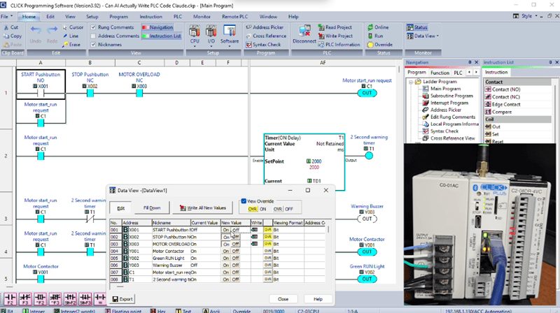
Press start — the buzzer sounds, two seconds pass, the motor output comes on and the green light follows. Drop the stop input, then the overload input, and each one kills the motor. I proved the logic shape first in a free online ladder simulator, which is a good no-hardware check before you wire anything.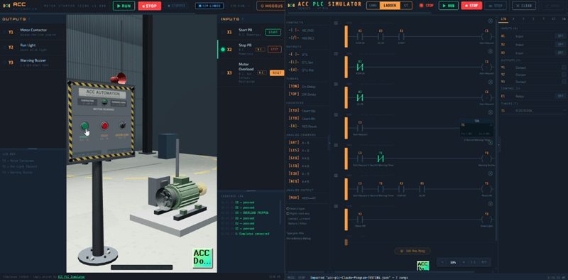
Only after it passed every one of those checks would I let it near a real motor — and even then, with the overload hardwired as a backstop.
My verdict on AI PLC code
Yes, AI can write it. I went in expecting to catch it out, and both ChatGPT and Claude wrote correct, working ladder logic for a real task, each in a sound and different style. For drafting, for learning, and for a second set of eyes, AI is genuinely good at this now, and I am not going to pretend it is not.
But writing correct code for a task I specified perfectly is not the same as programming your machine. It does not know your wiring, it did not think about hardwiring the overload, and it will never be responsible for what your program does. The limit is no longer whether AI can write a rung. The limit is that it cannot see your machine, and it cannot own the outcome. You can, and you do.
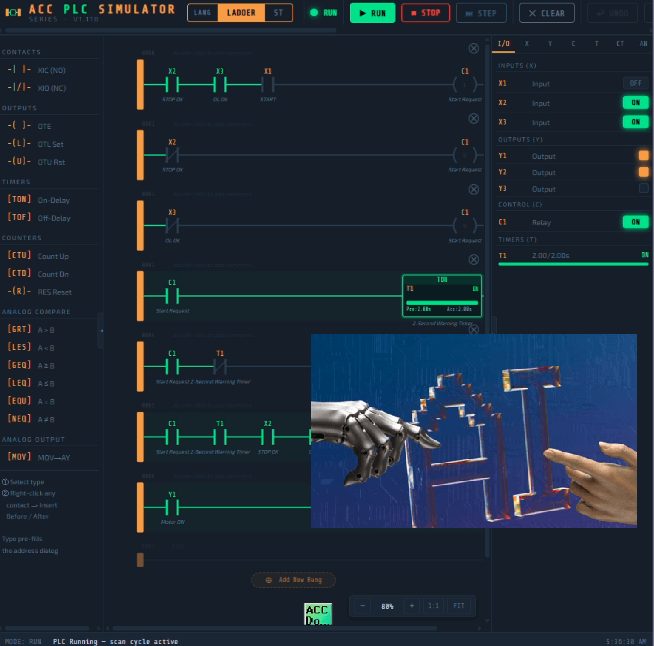
So use it the way I do. Write a clear, specific prompt, let the AI draft the logic, then verify every line, test with the outputs isolated, keep the safety functions in hardware, and put your name on it only when you understand it. Do that, and AI makes you a faster programmer. Skip it, and it will eventually cost you.
Watch on YouTube: Can AI Actually Write PLC Code? I Put It to the Test…
Downloads and Resources
- CLICK Programming Software (Free Download Link)
- CLICK PLC Instruction Set (Free Reference)
- ACC PLC Simulator (Free)
- Using AI to Program a CLICK PLC
- CLICK PLC Series
- PLC Beginner’s Guide
- Shop the hardware: AutomationDirect
- Parts Guide
If you have any questions or need further information, please contact me.
I hope this is helpful.
Regards,
Garry
ACC Automation
http://www.accautomation.ca