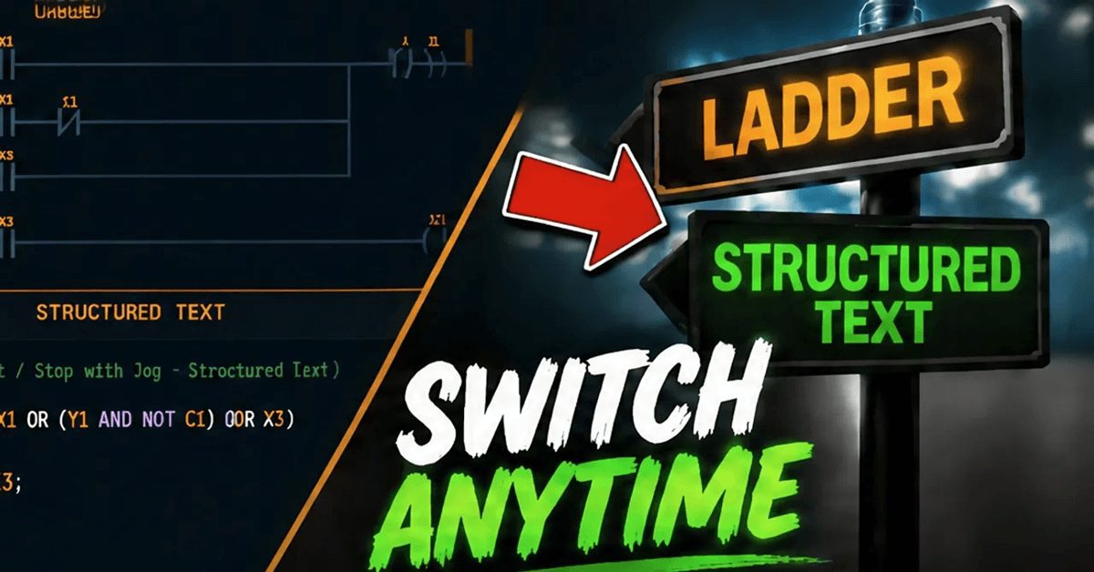
Structured Text is widely recognized as the fastest-growing PLC programming language. It is an IEC 61131-3 standard text-based language that reads like Pascal or C. If you have worked with any high-level programming language, ST will feel familiar. And if you have only used ladder logic, ST opens up a new way to think about PLC programs. The ACC PLC Simulator is the first free Structured Text PLC simulator that lets you write, test, and debug ST code right in your browser with interactive 3D scene feedback.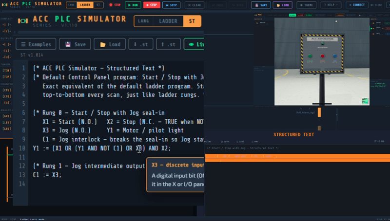
The ACC PLC Simulator now supports Structured Text as a first-class programming mode alongside ladder logic. You can switch between ladder and ST with a single click, and both modes use the same I/O, the same 3D scenes, the same Modbus bridge, and the same gamepad support. There is nothing extra to install. It is built right into the simulator.
Try it now: accautomation.ca/simulator/
Why Learn Structured Text
Here is why ST matters if you are serious about PLC programming.
Most modern PLCs support ST. Allen-Bradley, Siemens, CODESYS-based platforms, Beckhoff, Schneider, and many others all support IEC 61131-3 Structured Text. Practicing in a structured text PLC simulator gives you a transferable skill that works across brands.
ST is better than ladder for math-heavy logic. Analog scaling, PID calculations, data manipulation, and complex conditional logic are all cleaner and faster to write in ST than in ladder. If you have ever tried to build a multi-step analog scaling calculation in ladder, you know what I mean.
ST is the language that industry is moving toward. Many job postings now list ST as a required or preferred skill. The sooner you start practicing, the better your position.
Switching to Structured Text Mode
Open the simulator at accautomation.ca/simulator/.
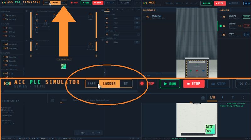
The ladder editor disappears, and a text editor appears in its place. This is where you write your Structured Text program. The I/O panel on the right stays exactly the same. The toolbar buttons for RUN, STOP, and STEP work exactly the same. The Connect button for 3D scenes works exactly the same. The only change is the programming language.
Your mode choice is remembered across reloads. If you close the browser and come back, it will be in whatever mode you left it in.
The Shared I/O Model
This is important to understand. Ladder and ST both read and write the same memory. Both modes use the same X, Y, C, AX, and AY registers. You write a program in ladder or ST, not both at the same time. But the I/O is identical.
That means every 3D scene works with ST programs unchanged. The Modbus bridge works unchanged. The gamepad works unchanged. If you already built a Start/Stop/Jog circuit in ladder for the Control Panel Scene, you can write the same program in ST and connect to the same scene with the same I/O addresses.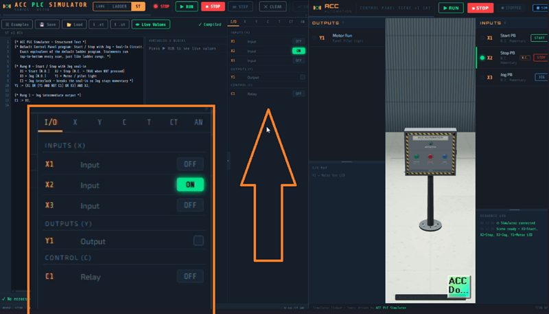
Here are the hardware addresses available in ST. These are pre-declared. Do not put them in a VAR block.
| Name | Type | Description |
|---|---|---|
| X1 through X16 | BOOL | Discrete inputs |
| Y1 through Y16 | BOOL | Discrete outputs |
| C1 through C256 | BOOL | Internal relays |
| AX1 through AX8 | INT (0-4095) | Analog inputs |
| AY1 through AY4 | INT (0-4095) | Analog outputs |
Your First ST Program — Start/Stop with Jog
Here is the default Structured Text program that ships with the ACC PLC Simulator. It is the exact equivalent of the default ladder program used with the Control Panel Scene.
(* Rung 0 — Start / Stop with Jog seal-in
   X1 = Start (N.O.)   X2 = Stop (N.C. — TRUE when NOT pressed)
   X3 = Jog (N.O.)     Y1 = Motor / pilot light
   C1 = Jog interlock — breaks the seal-in so Jog stays momentary *)
Y1 := (X1 OR (Y1 AND NOT C1) OR X3) AND X2;

(* Rung 1 — Jog intermediate output *)
C1 := X3;
That is the entire program. Two lines of executable code. Let me break it down.
The first line does everything. X1 OR (Y1 AND NOT C1) OR X3 creates three parallel paths, exactly like the three branches in the ladder rung. X1 is the Start button. Y1 AND NOT C1 is the seal-in path — Y1 feeds back on itself to stay latched, but only when C1 is FALSE. X3 is the Jog button. All three paths feed into AND X2, which is the Stop button. X2 is TRUE at rest because it is wired Normally Closed. When you press Stop, X2 goes FALSE and the AND fails.
The second line sets C1 equal to X3. When Jog is pressed, C1 goes TRUE. Back in the first line, Y1 AND NOT C1 becomes Y1 AND FALSE, which breaks the seal-in path. The motor runs through the X3 branch only. Release Jog and both X3 and C1 go FALSE. Y1 drops because there is no seal-in to hold it.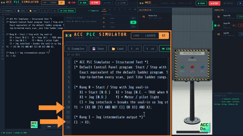
This is a direct translation of the ladder logic. The same addresses. The same behavior. The same I/O. Connect the Control Panel Scene and press the 3D buttons to test it.
Variables and Data Types
Your working variables go in VAR blocks. You must declare them before you use them.
VAR
  Count    : INT := 0;
  Level    : REAL;
  Alarm    : BOOL;
  Speed    : INT;
  Temps    : ARRAY[1..8] OF REAL;
END_VAR
The supported types are BOOL for true/false, INT and DINT and WORD for integers, REAL for floating point, TIME for durations using T# literals like T#500ms or T#2s, and ARRAY for indexed collections.
You can declare multiple variables of the same type on one line: a, b, c : INT;
Operators
ST uses familiar operators. Assignment is := not just the equals sign.
Boolean: AND, OR, XOR, NOT
Comparison: =, <>, <, >, <=, >=
Arithmetic: +, -, *, /, MOD, ** (exponent)
Boolean operators short-circuit. Divide by zero yields 0 instead of crashing.
Control Flow
This is where ST really shines compared to ladder.
IF/ELSIF/ELSE:
IF AX1 > 3000 THEN
  Y1 := TRUE;
  Y2 := FALSE;
ELSIF AX1 > 1500 THEN
  Y1 := FALSE;
  Y2 := TRUE;
ELSE
  Y1 := FALSE;
  Y2 := FALSE;
END_IF;
CASE for state machines:
CASE step OF
  0:     Y1 := TRUE;
  1, 2:  Y2 := TRUE;
  3..5:  Y3 := TRUE;
ELSE
  Y4 := TRUE;
END_CASE;
FOR loops:
FOR i := 1 TO 8 BY 1 DO
  // process each input
END_FOR;
WHILE and REPEAT are also supported. Remember the PLC scan model. The whole program runs top to bottom every scan. Use function block timers for delays. Never use a WHILE loop to wait.
Function Blocks
Function blocks are instances that hold their state across scans. Declare them in VAR, call them each scan with named parameters, and read their outputs as members.
TON — On-Delay Timer:
VAR
  StartDelay : TON;
END_VAR

StartDelay(IN := X1, PT := T#2s);
Y1 := StartDelay.Q;
AY1 := StartDelay.ET;
Y1 turns on 2 seconds after X1 goes true. AY1 shows the elapsed time in milliseconds.
CTU — Count Up:
VAR
  BoxCount : CTU;
END_VAR

BoxCount(CU := X1, R := X2, PV := 10);
Y2 := BoxCount.Q;
Y2 turns on when the count reaches 10. X2 resets the counter.
R_TRIG — Rising Edge:
VAR
  StartEdge : R_TRIG;
END_VAR

StartEdge(CLK := X1);
IF StartEdge.Q THEN
  Count := Count + 1;
END_IF;
StartEdge.Q is TRUE for exactly one scan when X1 transitions from FALSE to TRUE.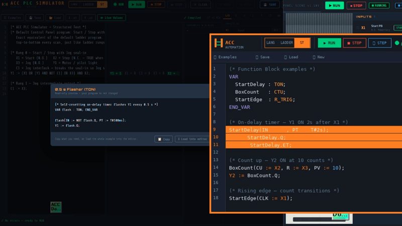
The full list of supported function blocks is TON, TOF, TP, CTU, CTD, R_TRIG, and F_TRIG.
Standard Functions
The simulator includes common IEC standard functions.
pct := LIMIT(0, AX1 * 100 / 4095, 100);
peak := MAX(AX1, AX2, AX3);
clamped := ABS(value);
scaled := TRUNC(level * 10.0);
Available functions include ABS, SQRT, MIN, MAX, LIMIT, TRUNC, ROUND, EXPT, SEL, SHL, SHR, and type converters like REAL_TO_INT and INT_TO_REAL.
User-Defined Functions and Function Blocks
You can define your own reusable functions and function blocks.
FUNCTION Scale : INT
  VAR_INPUT raw : INT; END_VAR
  Scale := LIMIT(0, raw * 100 / 4095, 100);
END_FUNCTION

VAR
  level : INT;
END_VAR

level := Scale(AX1);
AY1 := level;
Functions are stateless. Function blocks keep their internal state across scans, just like the built-in blocks.
The Variable Watch Panel
When you run an ST program, a live watch panel appears showing the current value of every variable and function block instance. This updates every scan so you can watch your logic execute in real time.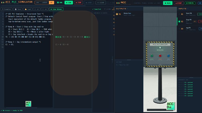
This is extremely useful for debugging. You can see the value of Running, the elapsed time of a TON timer, the current count of a CTU, and every other variable in your program without adding any debug code.
Error Handling
If your ST program has syntax errors, the simulator will refuse to enter Run mode and display a list of errors with line numbers and descriptions. Fix the errors and try again. This is the same behavior as a real PLC programming environment.
Runtime errors like possible infinite loops or other issues will stop the program and display the error with a line number in the status bar. The infinite loop guard prevents a bad WHILE TRUE from freezing your browser.
Connecting to 3D Scenes
Connecting to 3D scenes works the same way in ST mode. The structured text PLC simulator uses the same BroadcastChannel connection as ladder mode. Click CONNECT, select a scene, click LAUNCH. The scene sends X inputs to the simulator and receives Y outputs back. The scene can’t tell whether you’re using ST or ladder.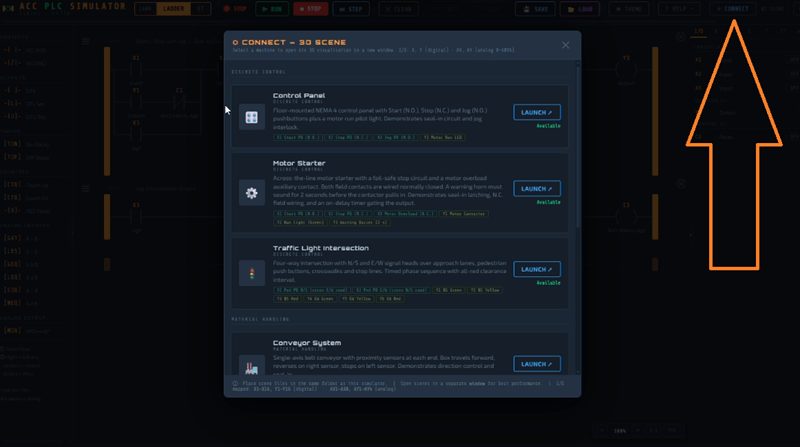
This means you can write the Control Panel Start/Stop/Jog program in ST, connect the panel scene, and press the 3D buttons to test your logic. Same experience. Different language.
Saving and Loading – Structured Text PLC Simulator
In ST mode, the toolbar SAVE and LOAD buttons store ST programs in named slots in the browser. You can also Export your program as a .st text file and Import .st files from disk. Your source auto-saves as you type and is restored on reload.
The simulator includes built-in ST examples covering seal-in, TON flasher, CTU counter, analog tank control, and a CASE-based traffic sequence. Use the Examples button to load them.
Ladder vs ST — Same Problem, Two Languages
Here is the Start/Stop/Jog side by side for comparison.
Ladder version (2 rungs):
- Rung 0: XIC X1 parallel with (XIC Y1 series XIO C1), parallel with XIC X3, series XIC X2, OTE Y1
- Rung 1: XIC X3, OTE C1
ST version (2 lines):
Y1 := (X1 OR (Y1 AND NOT C1) OR X3) AND X2;
C1 := X3;
Both produce the same behavior. Both use the same I/O addresses. Both connect to the same 3D scenes. The ST version is a direct translation — the same Y1 seal-in, the same C1 interlock, the same X2 Stop in series. The structured text PLC simulator makes it easy to compare both approaches side by side. Learn both, and you can work on any PLC platform.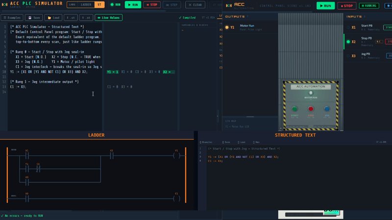
Tips for Getting Started with ST
Start with programs you already know in ladder. Rewrite the Start/Stop circuit in ST. Then the conveyor. Then add a timer. Converting familiar logic is the fastest way to learn the syntax.
Use the variable watch panel constantly. It is your best debugging tool. Every variable and every function block output is visible in real time.
Use named parameters for function block calls. Writing StartDelay(IN := X1, PT := T#2s) is much clearer than StartDelay(X1, T#2s), especially when you come back to the code later.
Comment your code. Use // for inline comments and (* *) for block comments. The same rule applies as ladder: if you cannot explain what a line does, do not run it.
Remember the scan model. Your entire ST program executes top to bottom every scan. There is no looping to wait for something to happen. Use TON, TOF, and state variables to manage timing and sequencing.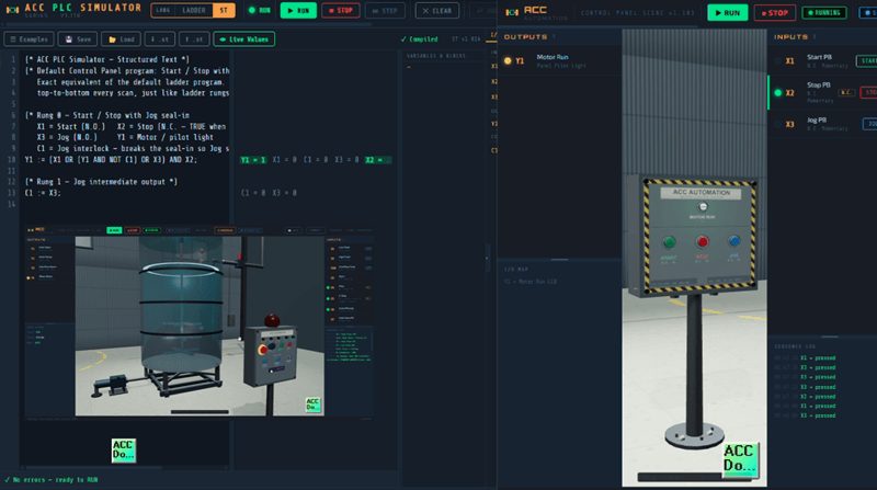
What is Next
Structured Text is the second programming language in the ACC PLC Simulator and it opens up the structured text PLC simulator to a much broader audience. If you have been working in Python, C, or JavaScript and want to learn PLC programming, ST will feel natural. If you have been working in ladder and want to expand your skills, ST is the next step.
Head over to accautomation.ca/simulator/ and click the ST button in the toolbar to get started.
If you have any questions or need further information, please contact me. Thank you, Garry