We will now look at the parts of a PLC system. When I was in school PLCs were just in their infancy. We were taught that the PLC consisted of the central processing unit (CPU), analog and digital inputs, and outputs. Everything was programmed with dedicated handheld devices and/or software devices on specialized hardware. We now have modern PLC systems that are capable of so much more. Let’s look at how we can now break up these modern PLC systems into the seven essential components.
CPU
Inputs and Outputs (I/O)
Analog I/O
Specialty I/O
Programming Tools
HMI
Networking
CPU – Central Processing Unit – PLC System Parts
PLC manufacturers use proprietary computer chips in their controllers. These are the brains in the controller to do the work we want. There has been an effort to standardize the programming languages of the PLC. IEC 61131-3 specifies the five different languages being:
• Structured Text (ST)
• Function Block Diagram (FBD)
• Sequential Function Chart (SFC)
• Instruction List (IL)
• Ladder Diagram (LD)
Support for a language does not mean that the key stokes for writing and implementing the logic is the same in each manufacturer‘s controller. Every manufacturer will have a different method of implementation. Additional information about programming languages can be obtained by viewing ‘What everybody ought to know about PLC programming languages.’
Every manufacturer will try to set themselves apart by quoting the execution time of the program code. This is the speed at which the program is looked at and the physical hardware is scanned or set. The following posts will explain the PLC program scan.
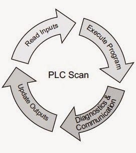
Who else wants to know how a PLC Scans?
Understanding the PLC Program Scan.
People/organizations get ‘locked’ into one manufacturer of PLC by having knowledge and hardware only of one supplier. Training personal throughout the organization on programming and troubleshooting can be expensive. This is also true of the actual hardware already installed and running on the plant floor.
The sizing and actual model number of a PLC are determined by all of the rest of the parts of the PLC system.
Inputs and Outputs (I/O) – PLC System Parts
Sizing of the PLC was traditionally done by the number of inputs and outputs that the system will control. When we talk of I/O, this is referring to discrete on/off devices. Inputs would be items like pushbuttons, switches, sensors, etc. Outputs would be items like motors, lights, solenoids, etc.
How PLC Inputs Work
How PLC Outputs Work
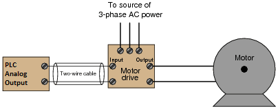
Analog I/O – PLC System Parts
The analog inputs and outputs on a PLC system refer to an input or output that gives us a range. An example of the input would be the weight of a product, speed of the motor, etc. Analog outputs would include setting the speed of the motor, controlling a proportional valve, etc.
How PLC Inputs Work
How PLC Outputs Work
Specialty I/O – PLC System Parts
High-speed counters, position control units (2 axes or more interpolated), Basic card modules, thermocouple / RTD input cards, etc. These are just a few samples of specialty cards that are available for specific tasks that the PLC may have to control. Manufacturers have started to incorporate a lot of these features within the standard PLC unit.
Programming Tools – PLC System Parts
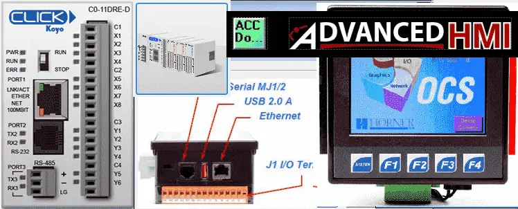
Small portable dedicated devices are sometimes available to program and troubleshoot the PLC. However the majority of the time now you will be using a computer running the software from the manufacture to program and troubleshoot the PLC. The computer is usually a windows based machine.
Simulators are also very common now when developing and testing your logic. You can limit the amount of troubleshooting required before installing on the factory floor when using a simulator. This may not be available on all software packages. Please refer to the unit you are using.
Here is an example: AdvancedHMI to communicate Modbus TCP to the Automation Direct Do-More Designer Software Simulator. The following is the sequence of operation:
Watch on YouTube : Running the Cylinder Sequence (PLC / HMI)
Note: All of the programs used are provided free of charge and are an excellent way to learn PLC / HMI programming.
Each manufacturer will have different specifications for the computer hardware and software required to run their package. (Example: Communication ports and Operating systems)
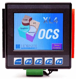
HMI – PLC System Parts
The HMI (Human Machine Interface) is a method in which the operator can control, adjust or troubleshoot the machine. It usually involves a visual screen to display information to the operator and/or touch screen/ keys for input back from the operator. HMI‘s can be built into the controller or as a separate item through networking.
Horner XL4 System Hardware
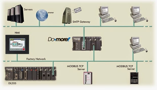
Networking – PLC System Parts
Networking is the ability to communicate to other devices in the system. This will involve the physical and software methods. The physical will be items such as the cable, signal voltages, and configuration. The software will consist of the protocol (language) used to communicate so each device understands the other. 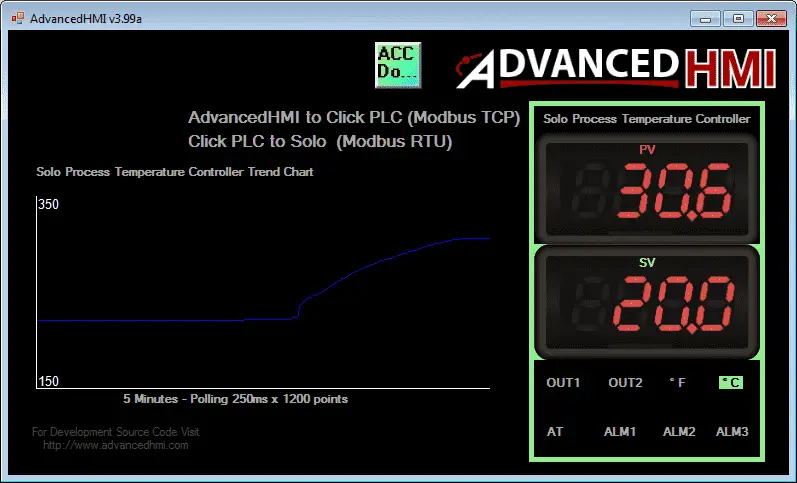
Peer to Peer Communications
Modern controllers will often have the ability to communicate with each other in the system by sharing a common memory block. Each PLC will have the ability to write to a certain section and read the entire memory block. This works well in applications where you need to decentralize the control system. (Smaller controllers networked together in a system.) A decentralized system is generally more flexible and quicker.
SCADA – Supervisory Control and Data Acquisition – This term is used to describe the ability to retrieve data from the system, make decisions, and store information.
Modern controllers will now have open protocols. This means that the information is published on how to communicate on the network.
Networking is a large topic. Here are a couple of posts that dive into some of the details.
How to Send Email to SMTP Server (VB)
Here’s is a quick way to send email (text) messages from the PLC
How to Implement the Omron PLC Host Link Protocol (VB)
How to Implement the Omron Host Link Protocol Part 2 – VBA
Implementing the Omron CX Server DDE and Excel
Modbus TCP Data Logging to Database
Creating an HMI Login Screen on AdvancedHMI
Deploying an AdvancedHMI Project
What Everybody Ought to Know About IP Addressing
The seven parts of the PLC system give you a good understanding of what to look for and ask about when specifying a PLC. Manufactures will assist you in specifying the controller by giving you information. The following is the system builder for Automation Direct.
https://www.automationdirect.com/systembuilder/index
Ask your local PLC supplier on sizing your next PLC project.
Watch on YouTube: The 7 Essential Parts of a PLC System
If you have any questions or need further information please contact me.
Thank you,
Garry
If you’re like most of my readers, you’re committed to learning about technology. Numbering systems used in PLCs are not difficult to learn and understand. We will walk through the numbering systems used in PLCs. This includes Bits, Decimal, Hexadecimal, ASCII, and Floating Point.
To get this free article, subscribe to my free email newsletter.
Use the information to inform other people how numbering systems work. Sign up now.

The ‘Robust Data Logging for Free’ eBook is also available as a free download. The link is included when you subscribe to ACC Automation.