
The Do-more PLC Modbus ASCII protocol will be used to communicate with a Solo process temperature controller. A sample program will explain in detail how this is accomplished through a serial port.
Modbus is a communication method used for transmitting information over serial lines between electronic devices. The device requesting the information is called the Modbus Master (Client), and the devices supplying information are Modbus Slaves (Servers). Modicon Systems initially developed this protocol.
The Modbus protocol comes in three basic types. Ethernet (Modbus TCP) or Serial (Modbus RTU or Modbus ASCII). Modbus TCP and Modbus RTU come as standard protocols in the BRX Do-More series of PLCs.
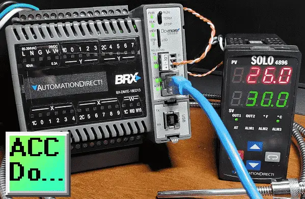
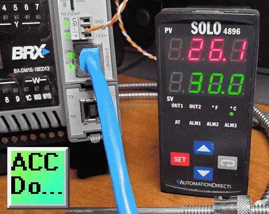
We will connect the BRX Do-More PLC to a Solo process temperature controller. This will be done using the Modbus ASCII protocol over serial RS-485 communication wire. (Media) The present and set values (PV / SV) will be read from the Solo controller, and the set value will be written when required. Let’s get started.
Previously in this BRX series PLC, we have discussed:
System Hardware – Video
Unboxing – Video
Installing the Software – Video
Establishing Communication – Video
Firmware Update – Video
Numbering Systems and Addressing – Video
First Program – Video
Monitoring and Testing the Program – Video
Online Editing and Debug Mode – Video
Timers – Video
Counters – Video
High-Speed IO – Video
Compare Instructions – Video
Math Instructions – Video
Program Control – Video
Shifting Instructions – Video
Drum Instruction – Video
Serial Communication – Modbus RTU to Solo Process Temperature Controller – Video
Data Logging – Video
Email – Text SMS Messaging Gmail – Video
Secure Email Communication Video
AdvancedHMI Communication – Modbus TCP – Video
Analog IO – System Configuration – Video
HTTP JSON Instructions – Video
Analog Dusk to Dawn Program – Video
INC DEC 512 Registers for DMX512 – Video
PID with PWM Output – Video
PID Ramp Soak Profile – Video
Do-More Simulator MQTT Publish / Subscribe – Video
BRX Do-More PLC MQTT Communications – Video
Stride Field Remote IO Modules Modbus TCP Ethernet
– Unboxing SIO MB12CDR and SIO MB04ADS Video
– Powering and Configuring Video
BRX Do-More PLC to Stride Field IO Modbus TCP – Video
BRX Do-More PLC Ethernet Remote IO Controller BX-DMIO
– Unboxing BX-DMIO Video
– Configuration and Programming Video
Modbus RTU TCP Remote IO Controller BX-MBIO
– Hardware Video
– Powering and Configuring Video
BRX Do-More PLC to Modbus Remote IO Controller BX-MBIO – Video
Our entire BRX D0-More series can be found here.
The programming software and manuals can be downloaded from the Automation Direct website free of charge.
Watch the video below to see the BRX Do-More PLC implement the Modbus ASCII protocol to communicate to the Solo process temperature controller.
Solo Process Temperature Controller
All Solo Standard Controllers are capable of Modbus communication.
The data and bit registers support the following Modbus function codes.
Data Registers
03: Read Holding Registers (maximum limit is read of eight registers)
06: Write Single Register
16: Write Multiple Registers (maximum limit is eight)
Bit Registers
01: Read Coils
02: Read Discrete Inputs (Both Function Code 1 & 2 read the same memory area.)
05: Write Single Coil (Write FF00H to set the coil or 0000H to reset the coil.)
The Modbus addresses for the Solo process temperature controller can be found in Chapter 7 of the manual. See the link below.
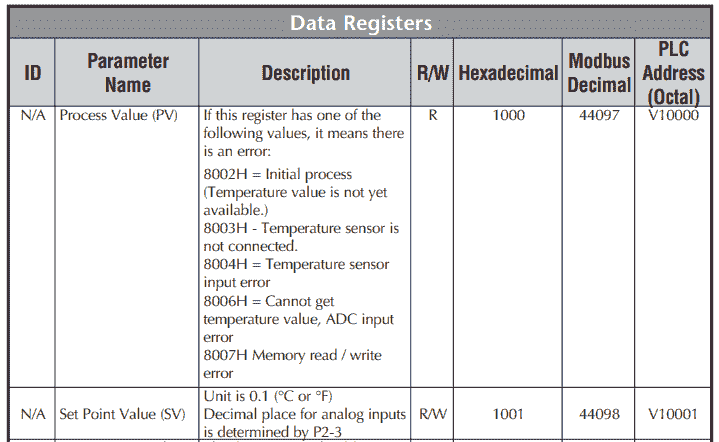
In our example, we will read the PV and SV values from the controller and write the SV when required.
Solo Process Temperature Controller Configuration
The first thing that we will do is set up the Solo Temperature Controller. Additional information can be found at the following link.
Wiring diagram:
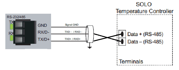
The solo process temperature controller needs to be set up before we can communicate with it. The default setting is ‘Off’ for the On-Line Configuration. Here is the way to change into the different modes in the Solo.
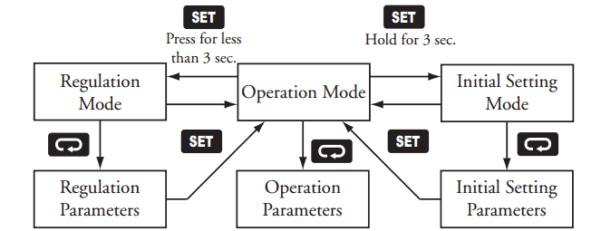
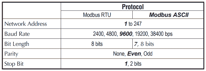
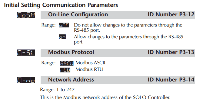
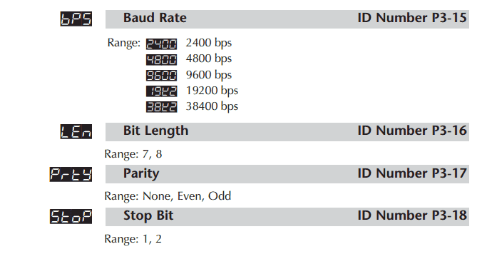
In the Initial Setting Mode, we will change the online configuration to on and make the changes to the Modbus settings as follows: 19200 Baud, Even, 7 Data Bits, 1 Stop Bit, Modbus ASCII Format. We will leave the default unit number as 1.
Our controller is now set to communicate.
Download the documentation and/or configuration and monitoring software at the following URL link:
Solo Process Temperature Controller Manual
Modbus ASCII Protocol Format
As the name states, ASCII (American Standard Code for Information Interchange) is used for communication messages.
Modbus ASCII marks the start of each message with a colon character “: ” (hex 3A).
The end of each message is terminated with the carriage return and line feed characters (hex 0D and 0A).
Example:
Sent data from the master
:010310000002EA
: – Start of message
01 – Address (unit) number
03 – Function Code (read multiple registers)
1000 – Data – Starting address to read
0002 – Data – Number of registers to read
EA – LRC (Longitudinal Redundancy Check) error checking byte
Response data from the slave
:01030400DC012CEE
: – Start of message
01 – Address (unit) number
03 – Function Code (read multiple registers)
04 – Number of return registers in bytes
00DC – Data returned PV in Hexadecimal = 22.1 degrees C
012C – Data returned SV in Hexadecimal = 30.0 degree C
EE – LRC (Longitudinal Redundancy Check) error checking byte
The bytes that you see in sending and receiving information are represented by two ASCII characters. Each ASCII character is 8 bits long. This means that Modbus ASCII sends more information back and forth than Modbus RTU.
Note: Since the space between bytes is variable, transmission through modems is possible with Modbus ASCII.
BRX Do-More PLC System Modbus Setup – Client (Master)
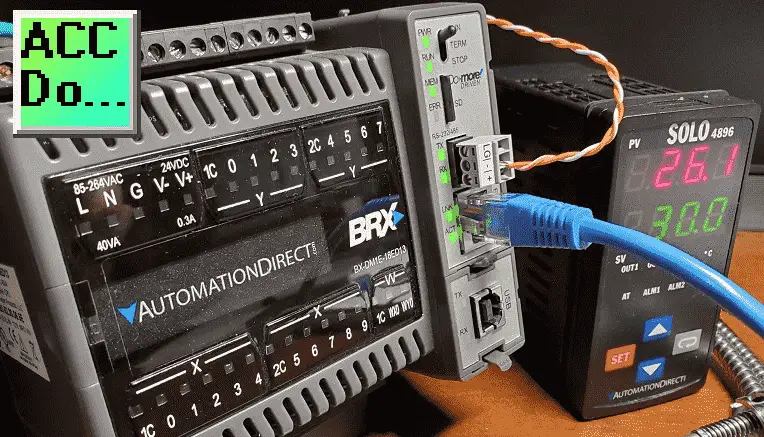
Modbus ASCII will be the serial (RS-485) method used for communication between the BRX Do-More PLC serial port and the Automation Direct Solo Process Temperature Controller.
We can address up to 247 (Solo 1 to 247) devices on this master-slave protocol. A maximum of 32 devices (Nodes) on the network can communicate with the master.
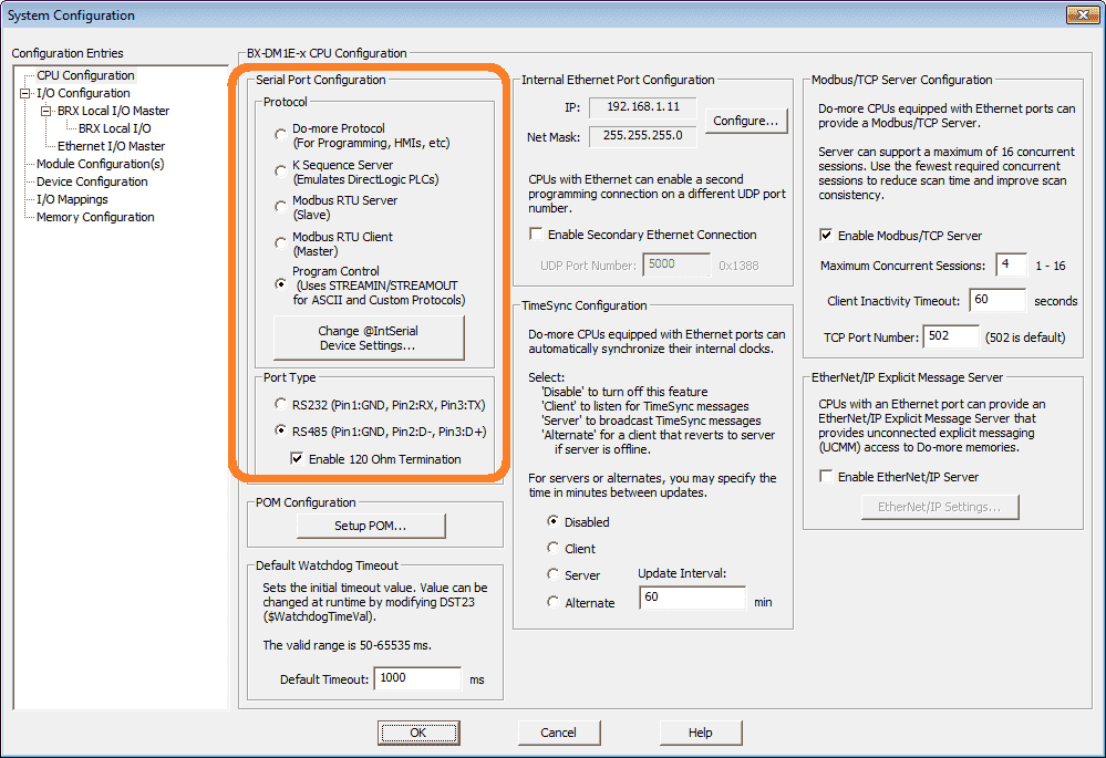
Using the Do-More Designer programming software, call up system configuration by selecting it from the main menu: PLC> System Configuration…
Under the protocol heading, we will select ‘STREAMIN/STREAMOUT’ for ASCII and Custom Protocols.
Note: Modbus RTU Server and Client are already incorporated into the controller. Modbus ASCII protocol will have to be assembled within our PLC program.
Under the port type, select RS-485 and enable the 120-ohm termination resistor.
Select Change @IntSerial Device Settings…
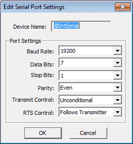
These serial port communication settings must be set to match our selection from the Solo controller. (19200, Even, 7, 1) Transmit control is unconditional, and RTS control will follow the transmitter. Select OK to save the parameters.
Our PLC is now set to start programming our Modbus ASCII protocol.
BRX Do-More PLC Program
Our sample program features a Main program that handles the overall logic. It will call up the program that handles communications with the Solo controller unit.
– Modbus_ASCII(BRX_to_Solo) – Modbus ASCII via Serial RS485
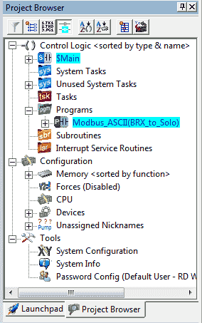
Using the Modbus ASCII Protocol to communicate with a Solo Process Temperature Controller
V1 – PV present value
V2 – SV set value
V100 – Change SV
When the value in V10 changes to a value greater than 0, it is then written into the Solo controller.
Modbus_ASCII(BRX_to_Solo)
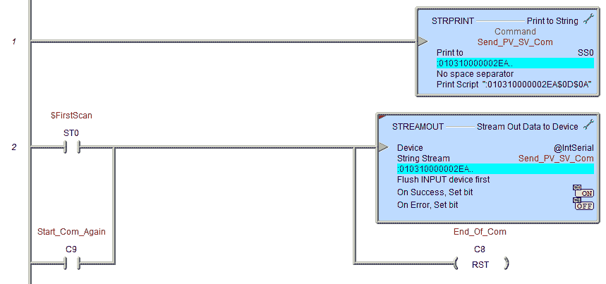
Modbus ASCII Send:
:010310000002EA
: – Start character
01 – Slave unit number
03 – Command Code – Multiple read
1000 – Data – Starting Address
0002 – Data – Number of addresses to read
EA – LRC – (Longitudinal Redundancy Check) error checking byte
The carriage return line feed is represented by $0D$0A. This marks the end of the message to the solo controller.
The STRPRINT instruction will put our print script into SS0. STREAMOUT is used to send the command out through our RS-485 port to the solo controller.
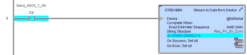
Modbus ASCII Receive:
:010304XXXXYYYYZZ
: – Start character
01 – Slave unit number
03 – Command Code – Multiple read
04 – Number of bytes times 2 returned (ASCII)
XXXX – Data from the first register – PV value
YYYY – Data from the second register – SV value
ZZ – LRC
The STREAMOUT success bit is used to trigger the STREAMIN instruction. This will place the returned information (ASCII) into SS1.
Note: $0D$0A is the exact delimiter sequence.
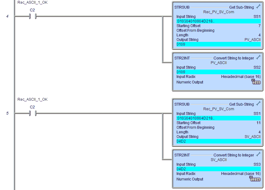
Using the STRSUB instruction, we place the PV and SV in SS2 and SS3. We then use the string-to-integer instruction (STR2INT) to convert the ASCII value to hexadecimal. This will then show us the correct values.
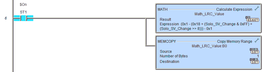
Calculation of LRC value for Sending SV to Solo
The LRC is calculated by adding together successive eight-bit bytes in the message, discarding any carries, then two’s complementing the result.
Modbus ASCII SV Write – :01061001XXXXYY (XXXX SV) (YY LRC)
01 + 06 + 10 + 01 = 18
Formula: 1 – (18 + SV LSB + SV MSB) – 1
The result word is then converted to ASCII text.
We are using a mask function by “logical AND ” and shifting instructions to add the SV LSB and MSB.
The resulting word is 2 bytes. We use the MEMCOPY to only move the least significant byte of information for our LRC.
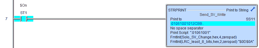
The string print instruction is then used to build up the write information to change the SV of the Solo.
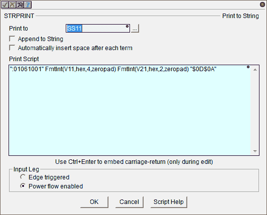
STRPRINT instruction has a print script that will format the information that we want.
“:01061001” – Modbus ASCII write starting at address 1001 hex (Solo SV)
FmtInt(V11,hex,4,zeropad) – SV information – format integer, hexadecimal value, 4 digits, pad with leading zeros.
FmtInt(V21,hex,4,zeropad) – LRC information – format integer, hexadecimal value, 2 digits, pad with leading zeros.
$N will put a “$0D$0A” into the script for the termination. (Carriage return / Line feed)
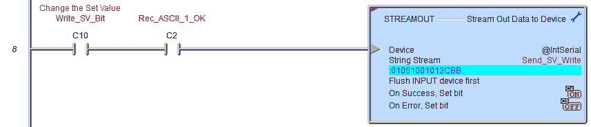
Send the Modbus ASCII string to change the Solo set value (SV).
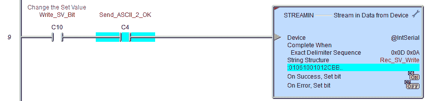
Receive the return string after changing the solo SV.
Modbus SV Write Receive:
:010602XXXXZZ
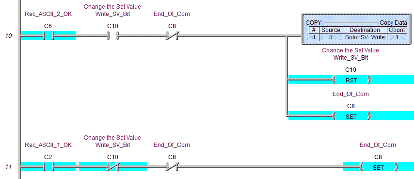
If we are writing the SV and it is finished, copy 0 to the SV write register. Then reset the write SV bit (C10) and set the end of communication bit.
If we are not writing and the read PV and SV are complete, then set the end of communication bit.
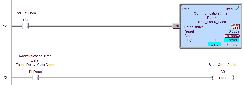
When the end of the communication bit is set, start a 20-millisecond timer. Once it has timed out, turn on the start communication again bit.
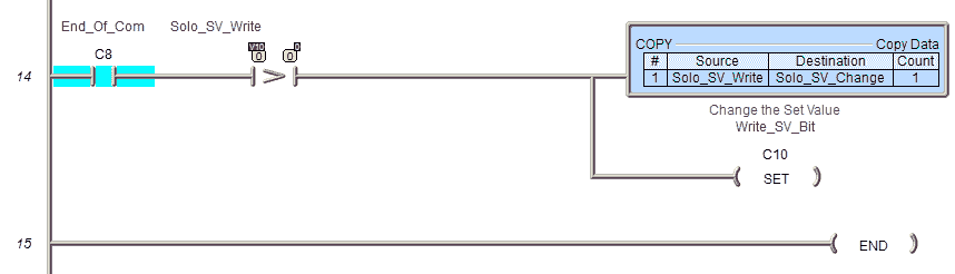
When the end of the communication bit is set, we check if the Solo SV Write (V10) value is greater than 0. If it is, we transfer V10 to V11 and set the write SV bit.
Watch the video below to see the operation of the BRX PLC program, which communicates with our Solo process temperature controller via Modbus ASCII protocol.
Download the BRX Do-More PLC program here.
BRX Series PLC from Automation Direct – Power to deliver
Overview Link (Configure and purchase a system)
Manuals and Product Inserts (Installation and Setup Instructions)
Do-More Designer Software v2.7.4 (Free Download Link) – The software includes all instruction sets and help files for the BRX Series PLC.
Modbus Learning Links:
Simply Modbus Frequently Asked Questions
Modbus TCP/IP Overview – Real-Time Automation
All You Need to Know About Modbus RTU – Video
Watch on YouTube: BRX Do-More PLC Modbus ASCII Protocol
If you have any questions or require additional information, please do not hesitate to contact me.
Thank you,
Garry
If you’re like most of my readers, you’re committed to learning about technology. Numbering systems used in PLCs are not difficult to know and understand. We will walk through the numbering systems used in PLCs. This includes Bits, Decimal, Hexadecimal, ASCII, and Floating Point. To get this free article, subscribe to my free email newsletter.
Use the information to inform other people how numbering systems work. Sign up now. The ‘Robust Data Logging for Free’ eBook is also available as a free download. The link is included when you subscribe to ACC Automation.