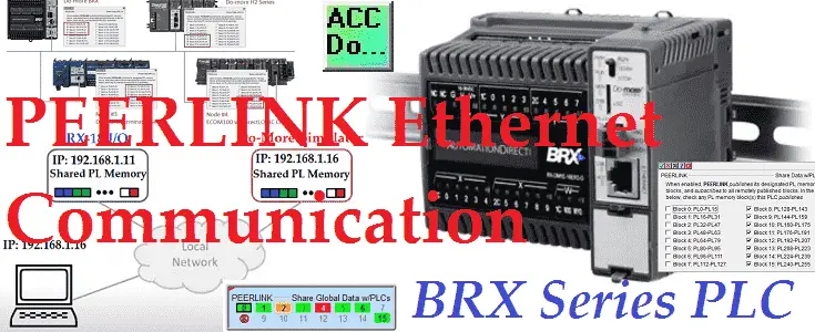
The BRX Do-More PLC Peerlink Ethernet communication network is one of the easiest networks to set up and run. Peerlink is a shared programmable logic controller (PLC) common memory area within a local network. Do-More central processing units (CPUs) or DirectLogic PLC systems using ECOM100 modules can read the entire area and write to their programmed area if selected.
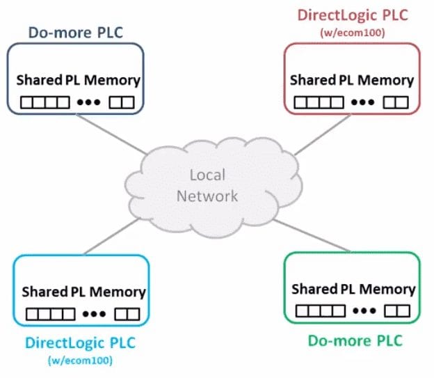
The network uses TCP/IP broadcast packets to publish the blocks of data PEERLINK (PL) memory to all of the devices attached. This broadcast will share the data network to the local domain only. Each member can optionally send data to the other members of the data-sharing network by electing to “publish” one or more blocks of PEERLINK (PL) memory.
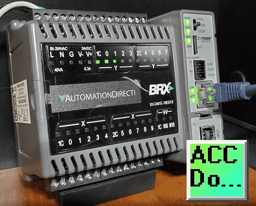
This can sound confusing at first, but it is the simplest network to set up. You can have your Peerlink network up and running in a matter of minutes. We will be setting up and demonstrating the Peerlink network using a BRX BX-DM1E-18ED13 and the Do-More Simulator. Let’s get started.
Previously in this BRX series PLC, we have discussed:
System Hardware – Video
Unboxing – Video
Installing the Software – Video
Establishing Communication – Video
Firmware Update – Video
Numbering Systems and Addressing – Video
First Program – Video
Monitoring and Testing the Program – Video
Online Editing and Debug Mode – Video
Timers – Video
Counters – Video
High-Speed IO – Video
Compare Instructions – Video
Math Instructions – Video
Program Control – Video
Shifting Instructions – Video
Drum Instruction – Video
Serial Communication – Modbus RTU to Solo Process Temperature Controller – Video
Data Logging – Video
Email – Text SMS Messaging Gmail – Video
Secure Email Communication Video
AdvancedHMI Communication – Modbus TCP – Video
Analog IO – System Configuration – Video
HTTP JSON Instructions – Video
Analog Dusk to Dawn Program – Video
INC DEC 512 Registers for DMX512 – Video
PID with PWM Output – Video
PID Ramp Soak Profile – Video
Do-More Simulator MQTT Publish / Subscribe – Video
BRX Do-More PLC MQTT Communications – Video
Stride Field Remote IO Modules Modbus TCP Ethernet
– Unboxing SIO MB12CDR and SIO MB04ADS Video
– Powering and Configuring Video
BRX Do-More PLC to Stride Field IO Modbus TCP – Video
BRX Do-More PLC Ethernet Remote IO Controller BX-DMIO
– Unboxing BX-DMIO Video
– Configuration and Programming Video
Modbus RTU TCP Remote IO Controller BX-MBIO
– Hardware Video
– Powering and Configuring Video
BRX Do-More PLC to Modbus Remote IO Controller BX-MBIO – Video
Modbus ASCII Protocol – Video
Our entire BRX D0-More series can be found here.
The programming software and manuals can be downloaded from the Automation Direct website free of charge.
Watch the video below to see the BRX Do-More PLC and Do-More Simulator share the common PEERLINK (PL) area on a local Ethernet network.
PLC Peerlink Area
The PEERLINK instruction works with a predefined section of memory named PL. The PL memory contains 256 locations named PL0 through PL255. These 256 locations are divided into 16 blocks. Each of these 16 data blocks consists of 16-Bit unsigned registers. These blocks provide the local storage for the data that is sent and received over the data-sharing network. In addition to the data blocks, PL memory contains entries for some Bits and Words that are available for use in a ladder program to monitor the runtime status of the PEERLINK network and to optionally control the updates to individual PEERLINK blocks.
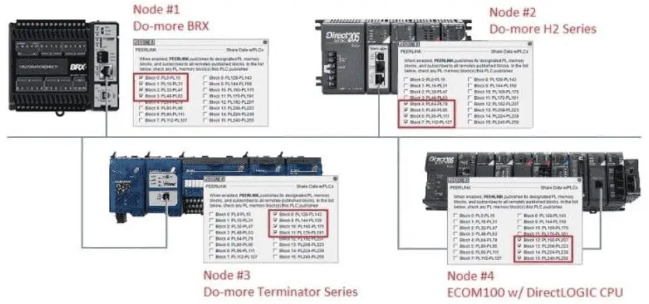
Each controller on the network can select what blocks that it will write. Only one controller can write to a block. If no blocks are selected, then it will still be able to read the entire Peerlink PL memory area.
Do-More PLC PEERLINK Example
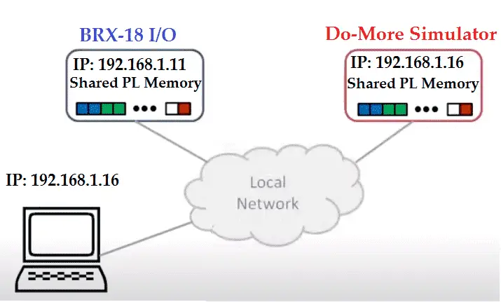
We will set up the BRX-18 IO unit to write to the first 8 blocks of the peerlink network and the last 8 blocks will be written by the Do-More Simulator. This way we will demonstrate the entire area being used.
Do-More PLC Simulator
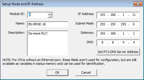
The Ethernet port needs to be configured with a TCP/IP address and Subnet Mask that is unique on the local network.
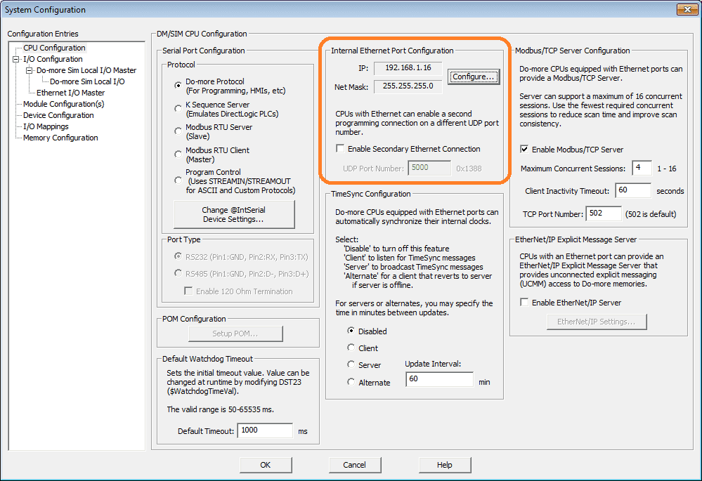
Call up the system configuration by selecting it from the main menu | PLC | System Configuration… This can also be selected under the Tools heading in the project browser. Select configure…
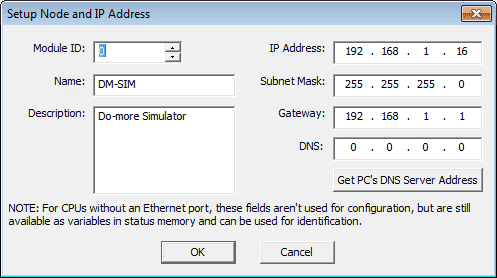
This IP address is the same as our computer because we are using the simulator. Once this is set we can return to the $Main program area. There can only be one PEERLINK instruction in a Do-more Designer project and it must be in the $Main code-block.

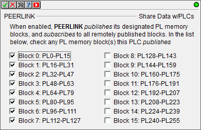
Calling up the PEERLINK instruction, we select the blocks that the PLC will write (publish) to the network. In our case, we writing Blocks 8 to 15. Since each block is 16 registers the address will be PL128 to PL255 for the blocks published.
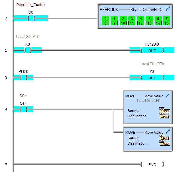
When the input logic to the PEERLINK instruction is on (the instruction is enabled the instruction will publish all of the blocks that it is configured to publish, and will process any PEERLINK data blocks that it receives. When the input logic is off, (the instruction is disabled), it does not publish any of its blocks and does not process any PEERLINK data blocks that it receives.
X0 will turn on PL128:0. This is the first bit of the first register in block 8.
PL0:0 will turn on Y0. The first bit of the first register in block 0 will turn on the first output of the simulator.
Analog input WX0 is moved to the second register in block 8 (PL129) and PL1 is moved to the analog output WY0 in our simulator.
The red flag in the upper left corner of the PEERLINK instruction means that the instruction is fully asynchronous. This means that information is sent and received without the involvement of the PLC scan.
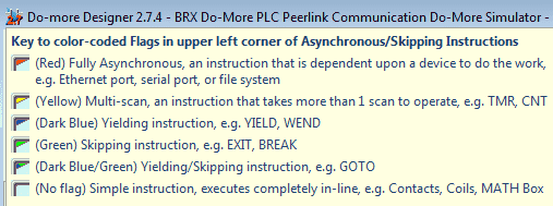
Here is a list of all of the colour codes.
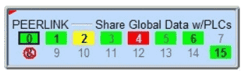
The PEERLINK instruction will have colour codes. Here is what each of the colours mean.
Green Background – indicates normal communication speed (receiving eight or more packets per second). In the example above Blocks 0, 1, 3, 5, 6 & 15 are communicating normally.
Yellow Background – indicates slower than normal communication rate, (receiving four to seven packets per second). In the example above Block 2 is communicating slowly.
Red Background – indicates a very slow communication rate, (receiving fewer than three packets per second). In the example above Block 4 is communicating very slowly or not at all.
Normal Box Background (with Grayed Numeral) – indicates that no controller on the network is publishing that particular block. In the example above Blocks 7, 9, 10, 11, 12, 13, and 14 are not being published.
The PEERLINK instruction also uses combinations of the following attributes to display important status information for each of the blocks:
• Bold Box Outline – indicates ‘My Blocks’, that is, the blocks that this controller is publishing. In the example above Block 0 is being published by this PLC.
• Green, Yellow, or Red background with Greyed Numeral – indicates that updates to the block have been inhibited, in the example above Blocks 3 and 5 have their updates inhibited. The inhibit bits for the blocks allow both the publisher and the subscribers to control updates to the controller’s PEERLINK memory.
•In the PLC that is publishing the block, setting the inhibit bit prevents that block from being published.
•In the PLC that is subscribing to a block, setting the inhibit bit prevents that block from being updated in the PLC.
• Red Circle with a Slash- indicates a configuration error meaning there is more than one controller configured to publish this block. In the example above Block 8 has a configuration error.
Using Data View we can monitor the values and bits to control the peerlink network.
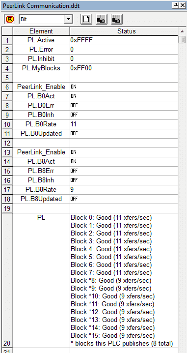
PL.Active will show you the current active blocks. In our case, we are using all 16 blocks that are represented by the value 0xFFFF.
PL.MyBlocks show in hexadecimal the blocks that this PLC will publish. 0xFF00 means blocks 8 to 15.
Each block can also be viewed and controlled. We will look at block 8 but this can apply to each of the 16 blocks of memory.
PL.B8Act – Active will display on or off for the bit depending on the status. If the publishing controller for the block turns off the PEERLINK instruction, then this will turn off this bit.
PL.B8Err – Bit will be on if an error occurs.
PL.B8Inh – Inhibit bit can be turned on by the publishing controller.
PL.B8Rate – This will show the rate per second that the block is being updated.
PL.B8.Updated – On means that new data has arrived in one or more locations in the designated data block during the last scan. Off means that the data in the designated block has not changed since the last scan.
PL – This will show you all of the conditions in the block and the rate if the long multi-line is displayed.
BRX PLC BX-DM1E-18ED13
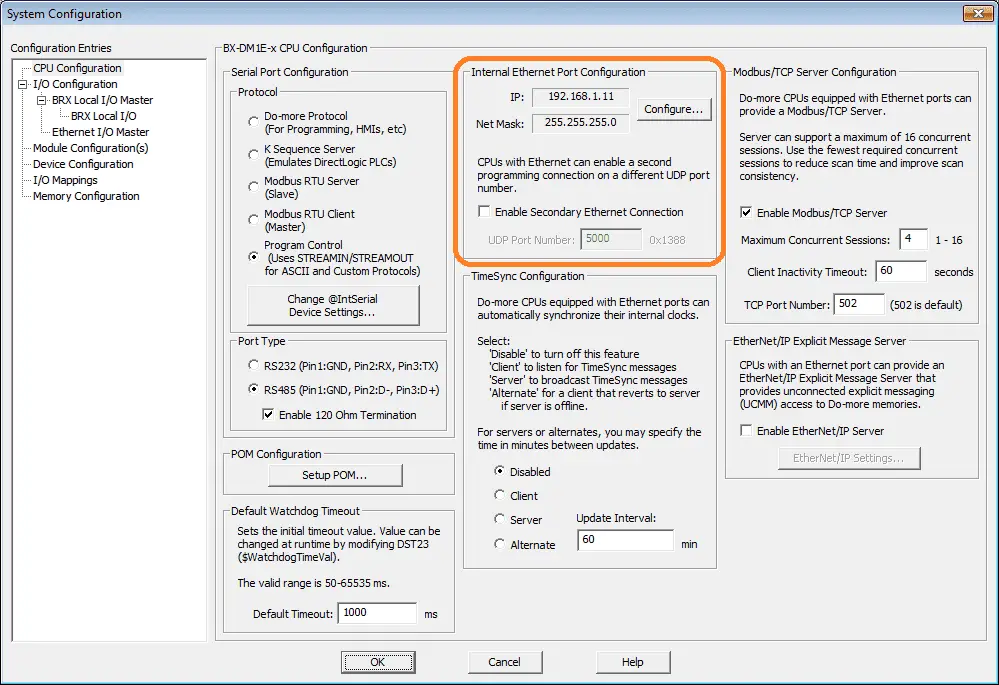
Call up the system configuration menu to ensure that the IP address has been set. (main menu | PLC | System Configuration…) Select configure.
This IP address must be unique on the local network.
The main program code block will contain PEERLINK instruction.
Our BRX will publish to the first 8 blocks of the PL memory area. (PL0 to PL127)
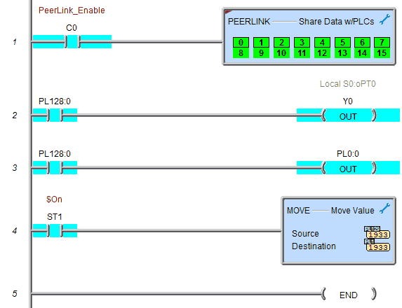
You can see that our peerlink instruction has the box outline indicating that it is controlling the publishing of these blocks.
PL128:0 will turn on Y0. This is the first bit of the first register in block 8 that will turn on our first output Y0. Remember that above this bit was controlled by X0 of our simulator.
PL128:0 will turn on PL0:0. This PL bit will also turn on the first bit of the first register of block 0. In our simulator, this will turn on output Y1 as well.
PL129 is moved to PL1. PL129 was controlled by the analog input WX0 of our simulator. We move this to PL1. In the simulator, this is used to control the analog output WY0.
Using Data View we can monitor the same control bits as above.
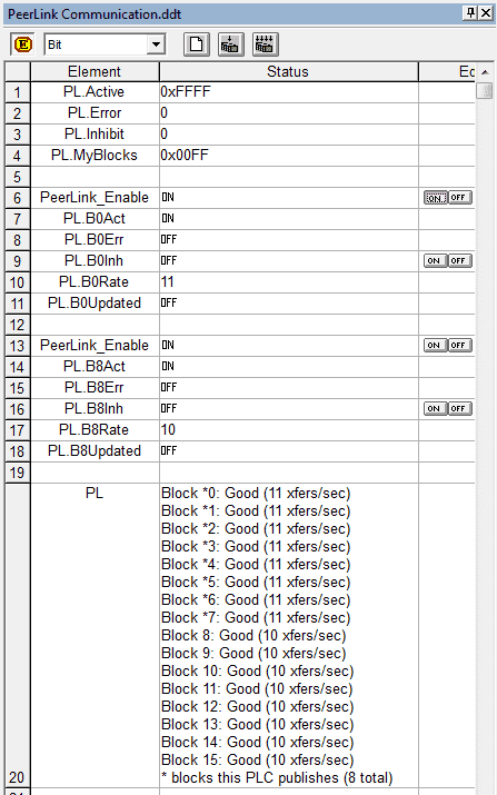
PL.MyBlocks – This will now show the value of 0x00FF to represent the blocks 0 to 7 being published by this controller.
PL will show and * on the blocks that are published by this PLC.
Watch the video below to see the running of the PEERLINK Ethernet communication network using our BRX PLC and the Do-More Simulator.
Download the BRX Do-More PLC program here.
BRX Series PLC from Automation Direct – Power to deliver
Overview Link (Configure and purchase a system)
Manuals and Product Inserts (Installation and Setup Instruction)
Do-More Designer Software (Free Download Link) – The software will contain all of the instruction sets and help files for the BRX Series PLC.
Watch on YouTube: BRX Do-More PLC Peerlink Ethernet Communication Network
If you have any questions or need further information please contact me.
Thank you,
Garry
If you’re like most of my readers, you’re committed to learning about technology. Numbering systems used in PLC’s are not difficult to learn and understand. We will walk through the numbering systems used in PLCs. This includes Bits, Decimal, Hexadecimal, ASCII, and Floating Point. To get this free article, subscribe to my free email newsletter.
Use the information to inform other people how numbering systems work. Sign up now. The ‘Robust Data Logging for Free’ eBook is also available as a free download. The link is included when you subscribe to ACC Automation.