We will now look at the C-More EA9 object shapes. These shapes can move and resize when connected to the PLC. The C-More HMI Panel software uses virtual components called Objects. These objects are programmable to simulate the functions that you require on your automation project. Pushbuttons, Switches, meters, and graphs are just a few of the objects that are available to you.
We can place several of these objects on one screen and have multiple panel screens. This helps you produce simple, intuitive looking human-machine interfaces.
We will be looking at our program we have so far developed (Simulate Project) and add shapes to a new screen page. These shapes can move and resize when interacting with the PLC. The navigation of the objects and additional information will also be discussed. Let’s get started.
Previously in this C-More EA9 HMI Panel series, we have done the following:
System Hardware
– Unboxing and Review Video
– Powering the Unit Video
Installing the Software – Video
System Setup Screens – Video
First Program
– Establishing Communication and Updating Firmware Video
– First Program Video
Panel to PLC and PLC to Panel Settings – Video
Common Screen Menu – Video
Simulate Project – Video
Watch the video below to see the Object Shapes in action on our C-More EA9 HMI Panel.
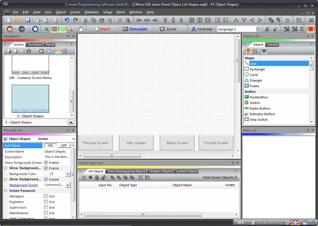
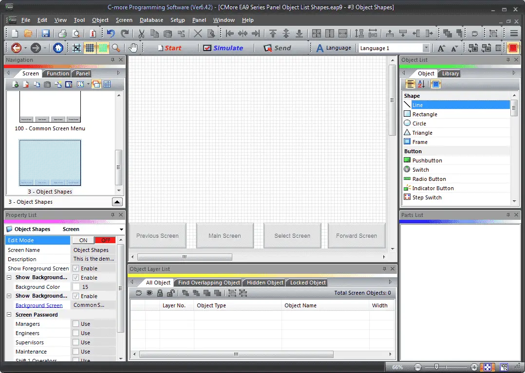
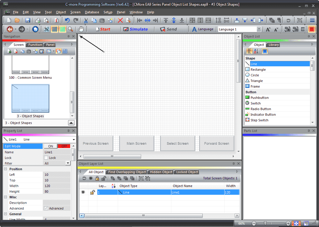
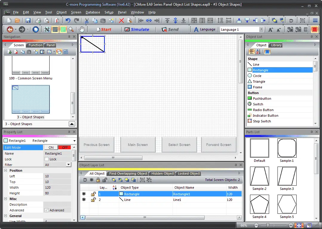
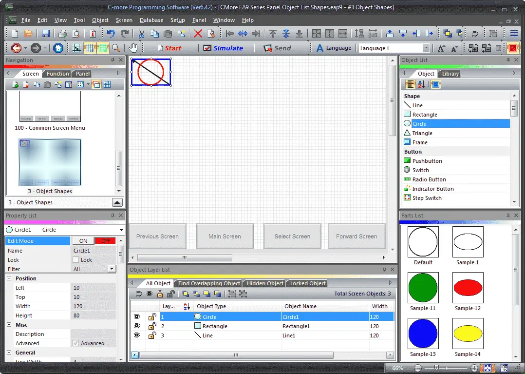
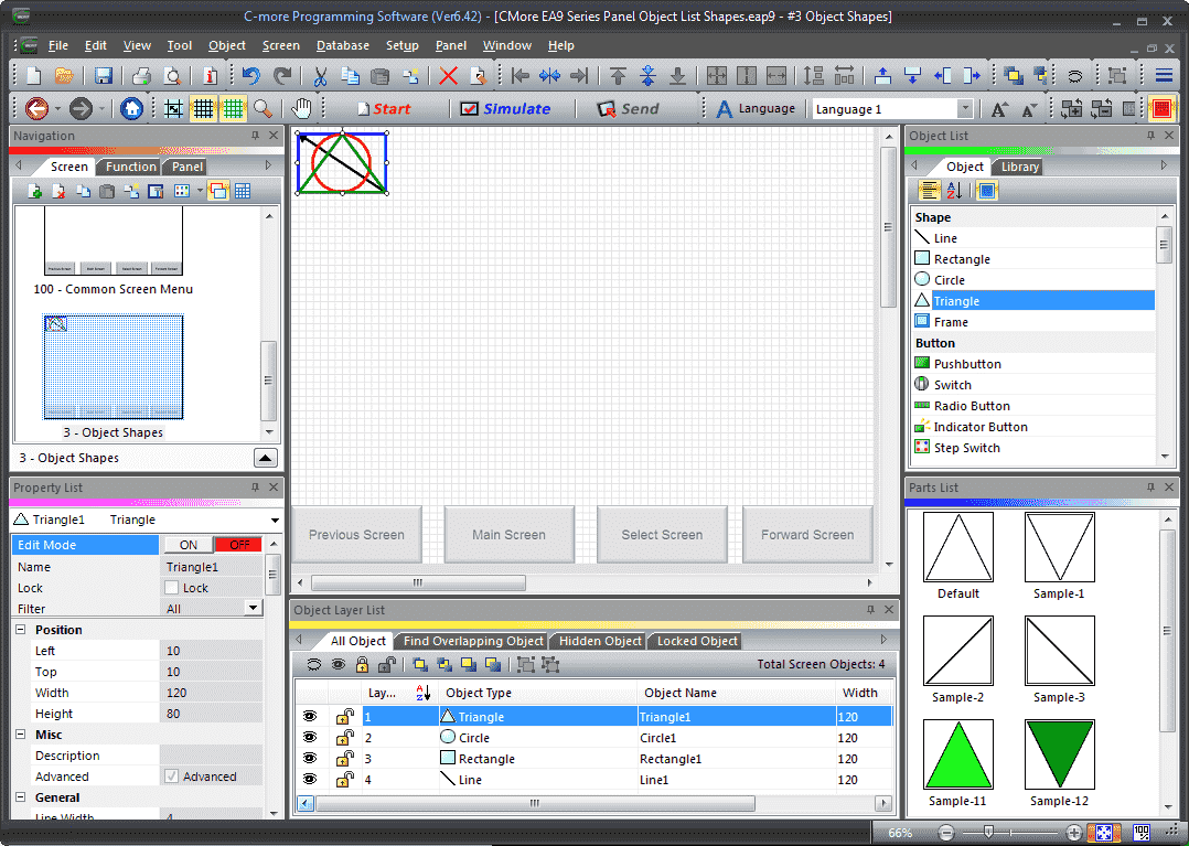
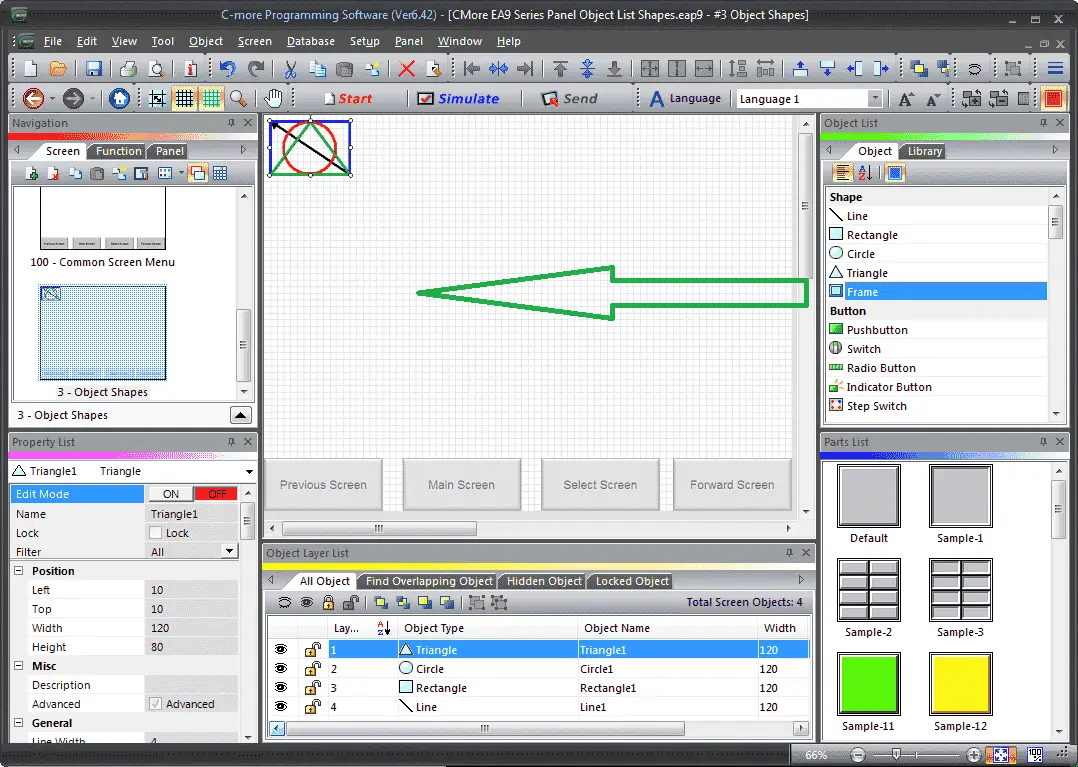
Navigation of the C-More Software
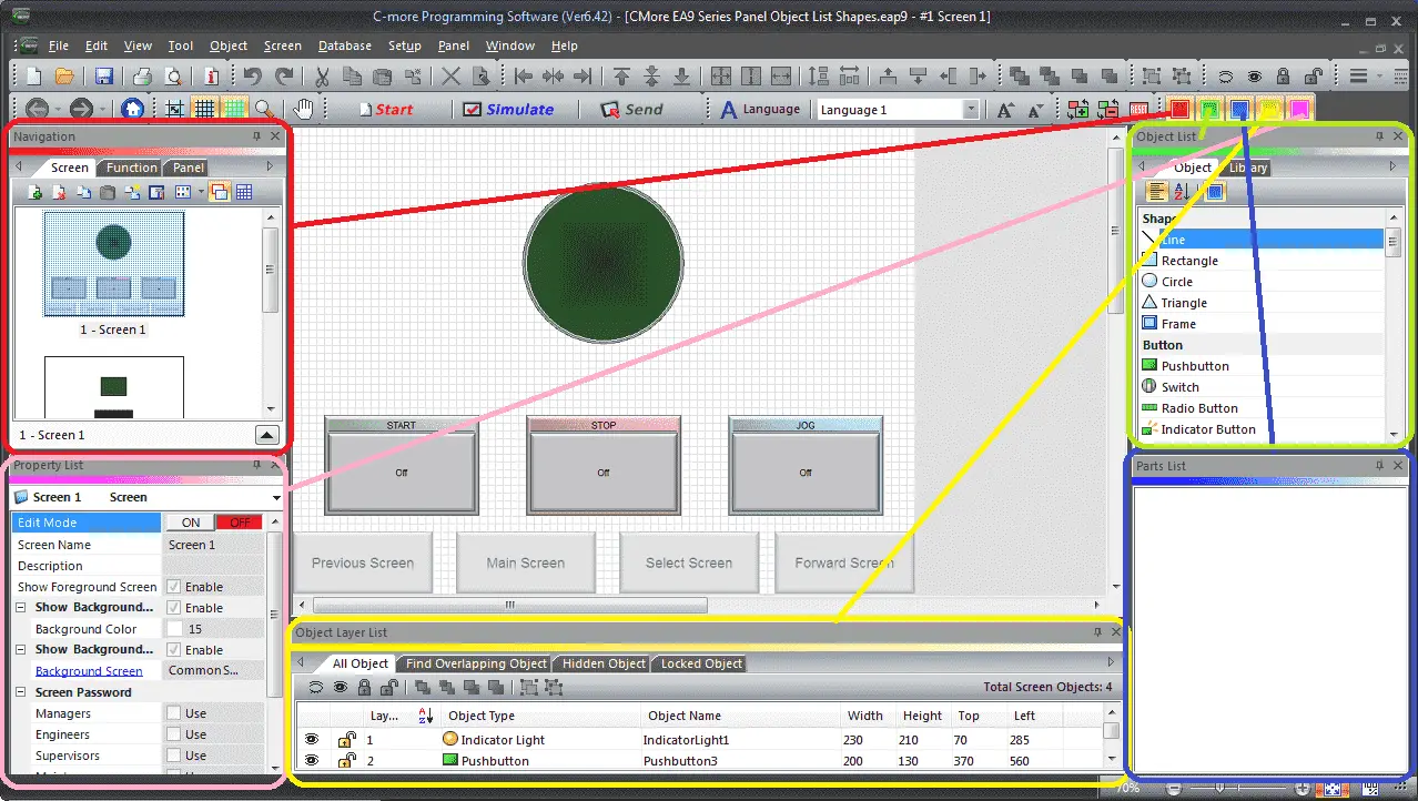
Each colour located on the main screen menu will control a window. Clicking the color will hide the menu if it is currently being displayed. If it is not being displayed when the menu will be shown. As shown before you can also pin the windows to see more of the work area.
Red – This will control the navigation window. The navigation window will show you the screens, functions and panel information.
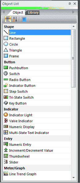
Green – This is the Object List menu. It contains all of the items that can be used on your HMI screen. We will be looking at the Shape objects later.
Blue – This is the Parts List. These are designed shapes that are in the list for you to use. The parts displayed will be for the object that has been selected in the object list. They are available so you do not have to create the object from scratch every time.
Yellow – The Object Layer List is a convenience feature for project design; it helps you work with an Object or groups of Objects on a screen. It doesn’t affect Object display or behavior on the panels itself.
Pink – The Property List Window provides a list of Properties specific to the selected object or screen. From this Window, you can select a Property field and edit the value directly on the field. The advantage of using this window is editing the same property on multiple objects.
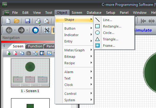
Another way to call the Objects for your HMI project is to use the main menu. Main Menu | Object | Shape | Line… would be the way to call up the line to be placed on your page in the c-more.
C-More Shapes Object
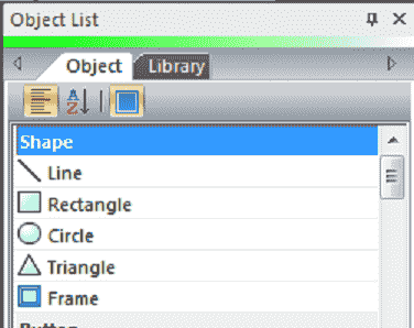
There are five different shapes that you can use to draw on your HMI C-more page. Line, Rectangle, Circle, Triangle, and Frame are the choices that you have when using shape objects.
Create a New Screen C-More
You can hit the new screen icon under the Screen tab in the navigation window or use the main menu | Screen | New Screen. Alternatively, you can use the keyboard short cut of Ctrl + N.
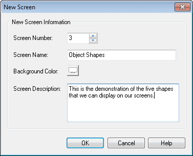
We will name the screen Object Shapes. The screen description can be used to describe the reason for the screen. Hit OK.
Our new screen will now be displayed. Under the property, list window turn on the editing and enable the show background. Select Common Screen Menu under the background screen. Turn off the edit mode under the property list.
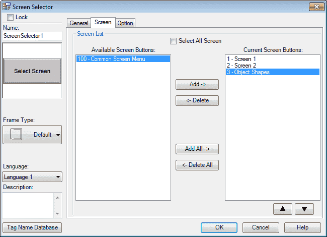
We must now add our new screen so we can select it when using the common screen menu. Select page 100. Select the Screen Selector button. Under the Screen, tab select the 3 – Object Shapes and hit the Add button so it moves it over to the Current Screen Buttons. Hit OK. We can now go back to our newly created Object Shapes screen page 3 from our navigation window.
Tag Name Database
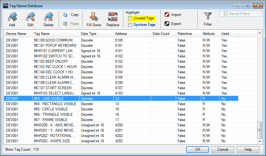
We will use the following five addresses to control the visibility of our shapes on the C-more HMI.
MI3 – Discrete On/Off – Modbus Address 10003 – Read Only – Line Visibility
MI4 – Discrete On/Off – Modbus Address 10004 – Read Only – Rectangle Visibility
MI5 – Discrete On/Off – Modbus Address 10005 – Read Only – Circle Visibility
MI6 – Discrete On/Off – Modbus Address 10006 – Read Only – Triangle Visibility
MI7 – Discrete On/Off – Modbus Address 10007 – Read Only – Frame Visibility
We will use the following addresses to control the x and y movement, rotation and size of our shapes.
MHR200 – Unsigned Int 16 – Modbus Address 40200 – Read/Write – X Movement
MHR201 – Unsigned Int 16 – Modbus Address 40201 – Read/Write – Y Movement
MHR202 – Unsigned Int 16 – Modbus Address 40202 – Read/Write – Rotational Movement
MHR203 – Unsigned Int 16 – Modbus Address 40203 – Read/Write – Shape Size
C-More Line Object
Locate the line shape under the Object List window.
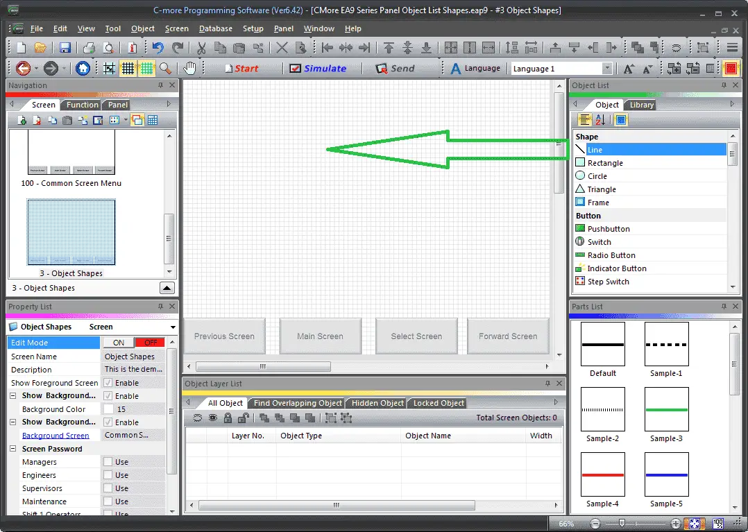
Click and hold the line shape and drag the line to the screen page location that you want the line to be displayed. Let go of the mouse button and the line window menu will appear.
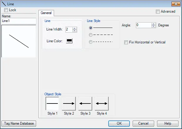
We have several options for the line. Width and colour can be selected and the line style has three options for you. The fixed horizontal or vertical selection will only allow the line to be vertical or horizontal. You can place the line on an angle that you specify. The object style will allow you to place an arrowhead on either end or both.
Select the Advanced option on the top right of the window.
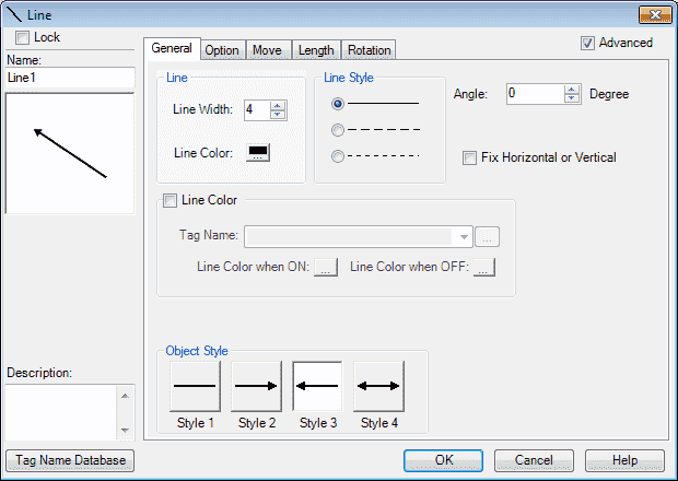
Additional tabs will now appear for programming. On the general tab, we will set the line width to 4 and leave the colour as black. Our object style will be 3, which will give us an arrow at one end. Select the Option tab.

Select the object visibility option. Our tag will be set to MI3 – Line Visible from the tag database that we set above. When this tag bit is on then the object can be seen on the screen. Select the Move tab.
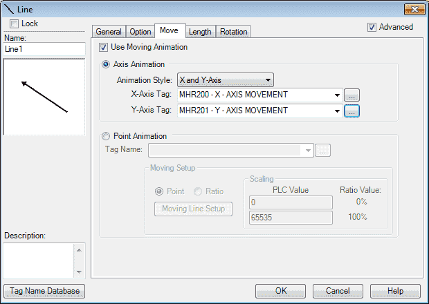
Select use moving animation. Under the animation style select X and Y-Axis. Our X-Axis Tag will be set for tag database MHR200. Our Y-Axis Tag will be set for tag database MHR201. This means that as the value in these tags changes, our object will move on the screen according to the x and y specified. Select the Length tab.
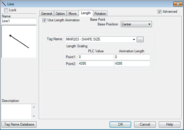
Select the use length animation. Our base point base position will be center. The tag database will be set for MHR203 – Shape Size. As the PLC value moves from 0 to 4095 the line object size will move from 0 to 4095 as well. Select the Rotation tab.
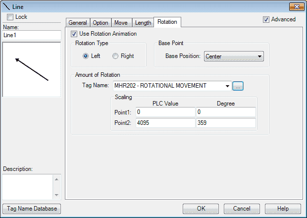
Select the use rotation animation. The rotation type will be left (counterclockwise). Our base point base position will be center. The tag database will be set for MHR 202 – Rotational Movement. As this tag changes from 0 to 4095 it will correspond to the line object rotating 0 to 359 degrees counter-clockwise (left). Select OK.
We will now use the mouse to position the line object to the top left corner. This way our x and y movement is positive.
C-More Rectangle Object
Locate the rectangle shape under the Object List window.
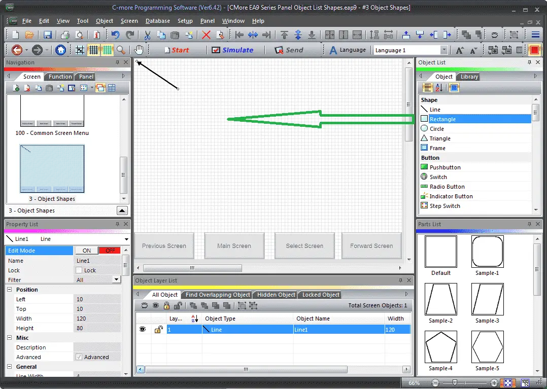
Click and hold the rectangle shape and drag it to the screen page location that you want the rectangle to be displayed. Let go of the mouse button and the rectangle window menu will appear.
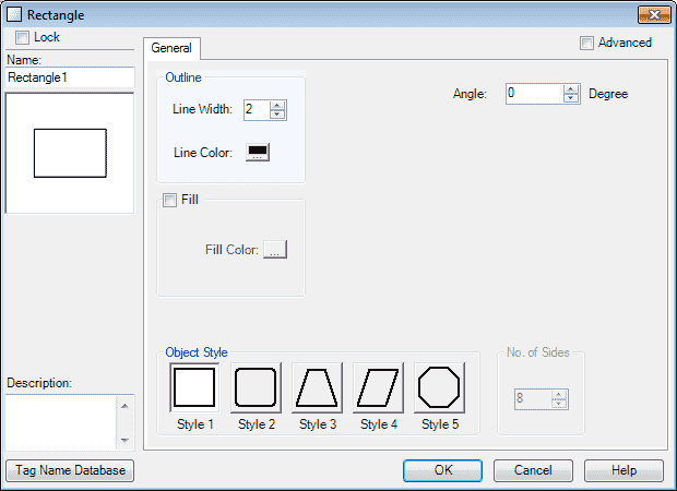
We have several options for the rectangle. Width and colour can be selected and the line style has five options for you. The fill will allow you to fill the rectangle with a colour. You can place the rectangle on an angle that you specify.
Select the Advanced option on the top right of the window.
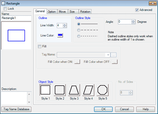
Additional tabs will now appear for programming. On the general tab, we will set the line width to 4 and set the colour as blue. Our object style will be 1, which will give us a true rectangle shape. Select the Option tab.
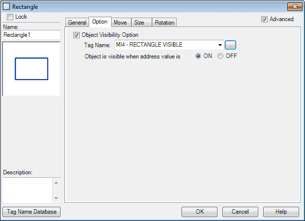
Select the object visibility option. Our tag will be set to MI4 – Rectangle Visible from our tag database that we set above. When this tag bit is on then the object can be seen on the screen. Select the Move tab.
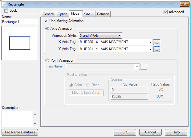
Select use moving animation. Under the animation style select X and Y-Axis. Our X-Axis Tag will be set for tag database MHR200. Our Y-Axis Tag will be set for tag database MHR201. This means that as the value in these tags changes, our object will move on the screen according to the x and y specified. Select the Size tab.
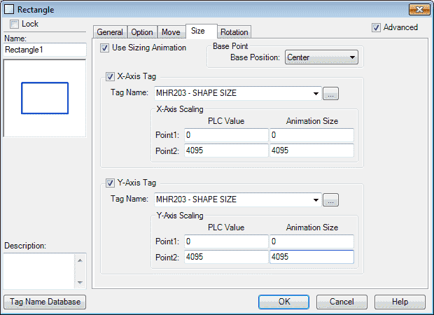
Select the use sizing animation. Our base point base position will be center. The X-Axis and Y-Axis tags will be set for MHR203 – Shape Size. As the PLC value moves from 0 to 4095 the line object size will move from 0 to 4095 as well on both axis. Select the Rotation tab.
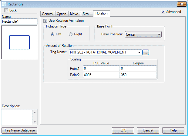
Select the use rotation animation. The rotation type will be left (counterclockwise). Our base point base position will be center. The tag database will be set for MHR 202 – Rotational Movement. As this tag changes from 0 to 4095, it will correspond to the rectangle object rotating 0 to 359 degrees counter-clockwise (left). Select OK.
We will now use the mouse to position the rectangle object to the top left corner. This way our x and y movement is positive.
C-More Circle Object
Locate the circle shape under the Object List window.
Click and hold the circle shape and drag it to the screen page location that you want the circle to be displayed. Let go of the mouse button and the circle window menu will appear.
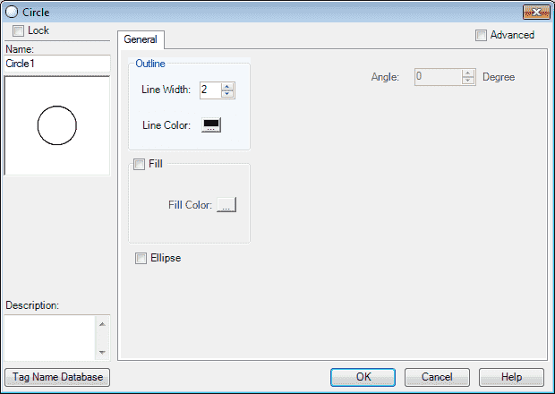
We have several options for the circle. Line width and colour can be selected. The fill will allow you to fill the circle with colour. You can also check the ellipse and then set the angle that you want.
Select the Advanced option on the top right of the window.
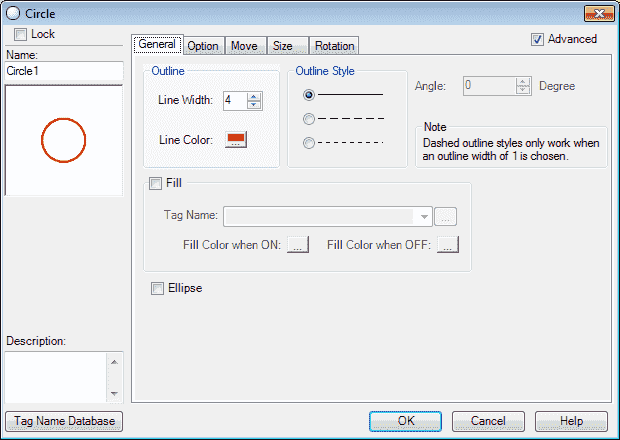
Additional tabs will now appear for programming. On the general tab, we will set the line width to 4 and set the colour as red. Our outline style will be left as the solid line default. Ensure that the fill is unchecked for our example. This will give you the option of having the fill colour change. Select the Option tab.
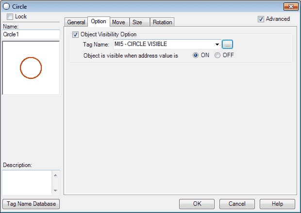
Select the object visibility option. Our tag will be set to MI5 – Circle Visible from the tag database that we set above. When this tag bit is on then the object can be seen on the screen. Select the Move tab.
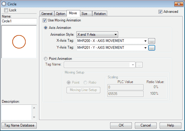
Select use moving animation. Under the animation style select X and Y-Axis. Our X-Axis Tag will be set for tag database MHR200. Our Y-Axis Tag will be set for tag database MHR201. This means that as the value in these tags changes, our object will move on the screen according to the x and y specified. Select the Size tab.
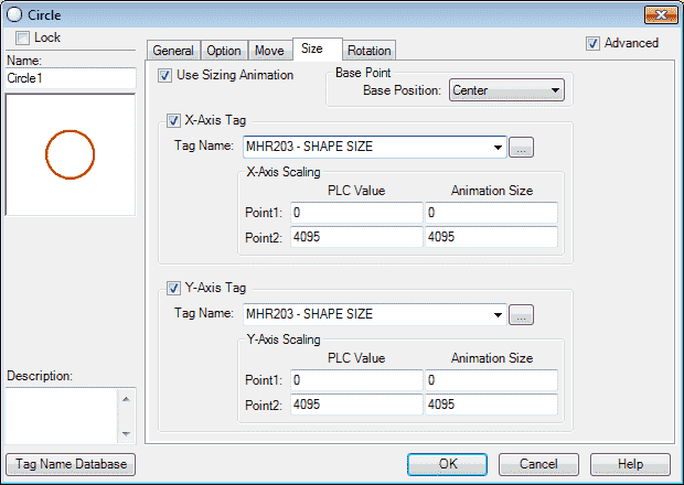
Select the use sizing animation. Our base point base position will be center. The X-Axis and Y-Axis tags will be set for MHR203 – Shape Size. As the PLC value moves from 0 to 4095 the line object size will move from 0 to 4095 as well on both axis. Select the Rotation tab.
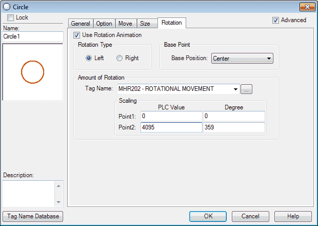
Select the use rotation animation. The rotation type will be left (counterclockwise). Our base point base position will be center. The tag database will be set for MHR 202 – Rotational Movement. As this tag changes from 0 to 4095, it will correspond to the rectangle object rotating 0 to 359 degrees counter-clockwise (left). Select OK.
Note: Since this is a circle our rotation will not be noticed.
We will now use the mouse to position the circle object to the top left corner. This way our x and y movement is positive.
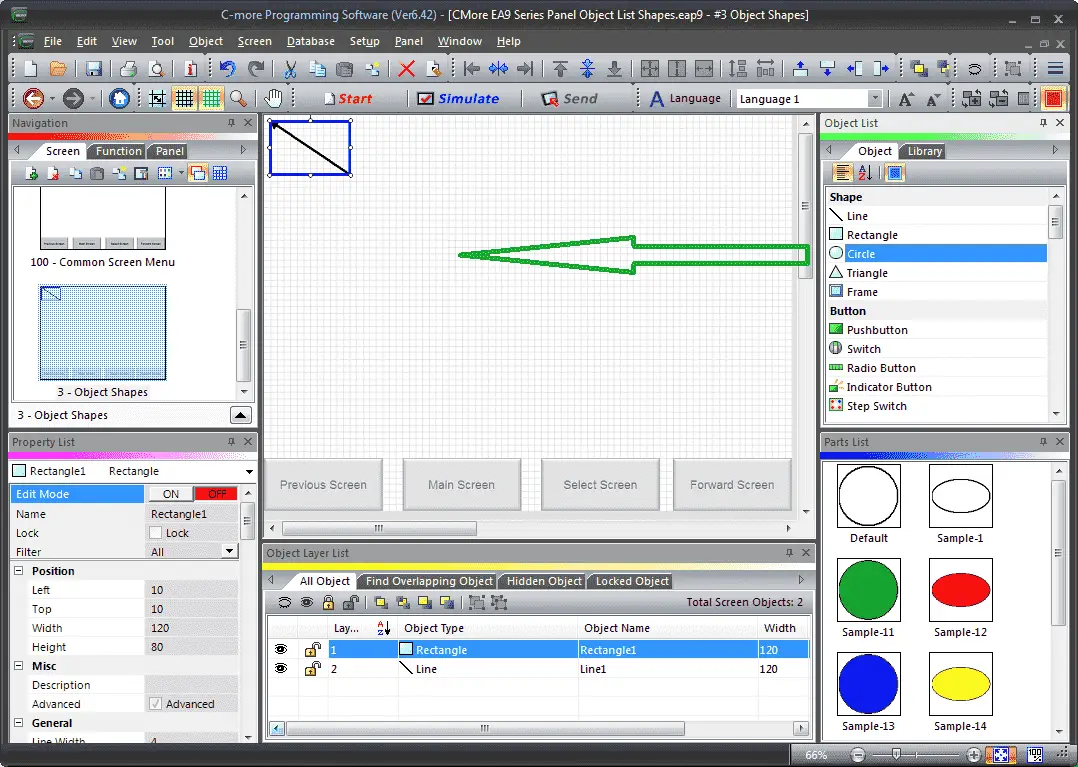
C-More Triangle Object
Locate the triangle shape under the Object List window.
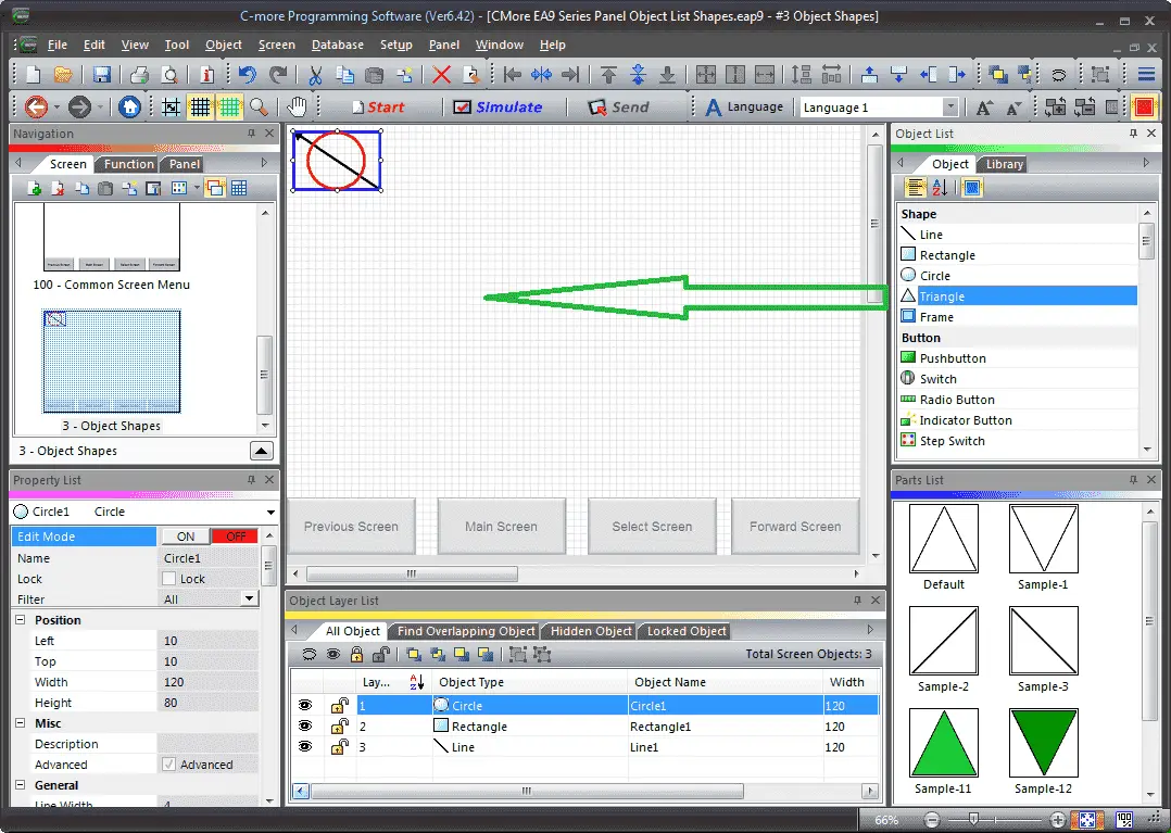
Click and hold the triangle shape and drag it to the screen page location that you want the triangle to be displayed. Let go of the mouse button and the triangle window menu will appear.
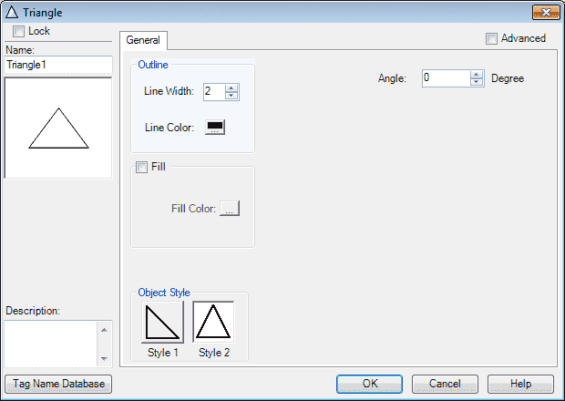
We have several options for the triangle. Line width and colour can be selected. The fill will allow you to fill the circle with colour. You can also select the object style and angle that you want.
Select the Advanced option on the top right of the window.
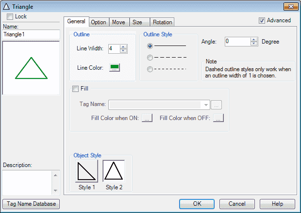
Additional tabs will now appear for programming. On the general tab, we will set the line width to 4 and set the colour as green. Our outline style will be left as the solid line default. Ensure that the fill is unchecked for our example. This will give you the option of having the fill colour change. Our option style will be style 2 and the angle will be left at 0 degrees. Select the Option tab.

Select the object visibility option. Our tag will be set to MI6 – Triangle Visible from our tag database that we set above. When this tag bit is on then the object can be seen on the screen. Select the Move tab.
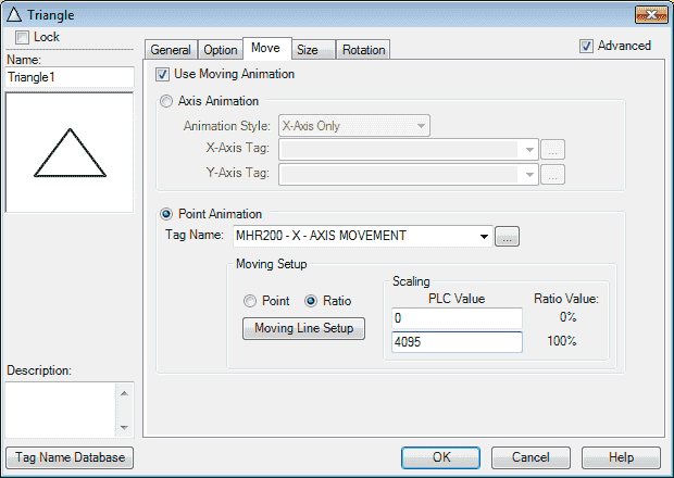
Select use moving animation. Under the animation style select point animation. Our Tag Name will be set for tag database MHR200. The moving setup will be set for ratio and the scaling will be set for 0 to 4095 which will represent 0 to 100 percent.
Select the Moving Line Setup.

As you click on this moving line setup window it will show you the movement of the object based on the percent. In our example, you can see a simple X diagram. Select OK to close the moving line setup and return to the move tab.
Note: This type of movement would be ideal to highlight an area of the machine picture.
Select the Size tab.
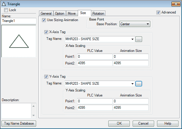
Select the use sizing animation. Our base point base position will be center. The X-Axis and Y-Axis tags will be set for MHR203 – Shape Size. As the PLC value moves from 0 to 4095 the line object size will move from 0 to 4095 as well on both axis. Select the Rotation tab.
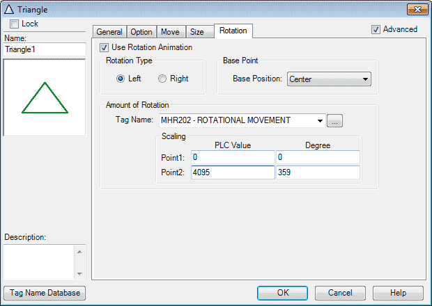
Select the use rotation animation. The rotation type will be left (counterclockwise). Our base point base position will be center. The tag database will be set for MHR 202 – Rotational Movement. As this tag changes from 0 to 4095, it will correspond to the rectangle object rotating 0 to 359 degrees counter-clockwise (left). Select OK.
We will now use the mouse to position the triangle object to the top left corner. This way our x and y movement is positive.
C-More Frame Object
Locate the frame shape under the Object List window.
Click and hold the frame shape and drag it to the screen page location that you want the frame to be displayed. Let go of the mouse button and the frame window menu will appear.
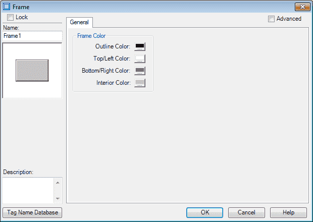
We have several options for the frame colour. Select the Advanced option on the top right of the window.

An additional tab will now appear for programming. On the general tab, we will set the object style to 1 and leave the colours as default. Select the Option tab.
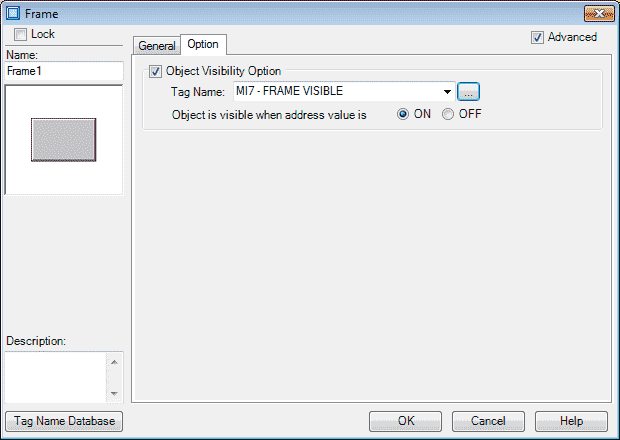
Select the object visibility option. Our tag will be set to MI7 – Frame Visible from the tag database that we set above. When this tag bit is on then the object can be seen on the screen. Select OK.
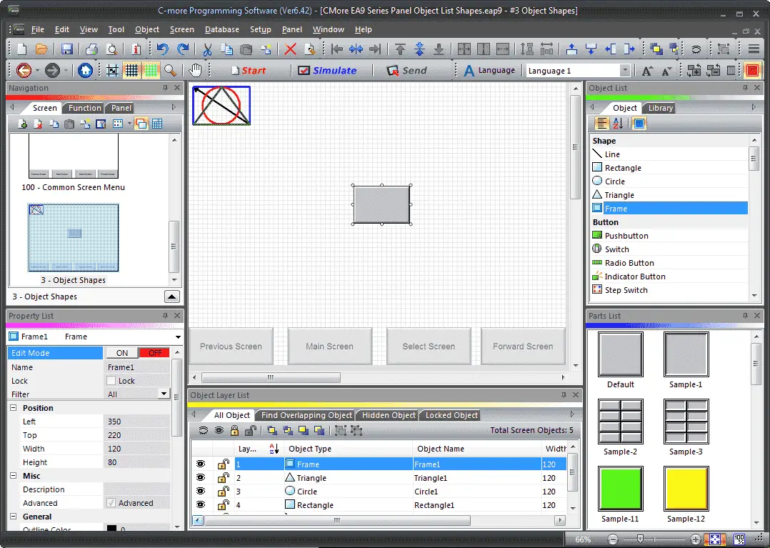
We will now use the mouse to position the frame object on our screen.
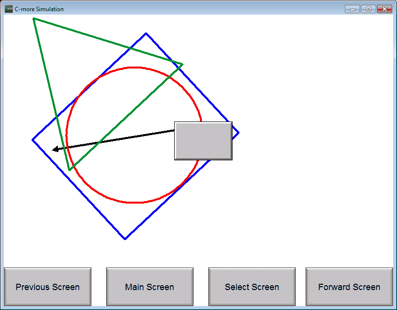
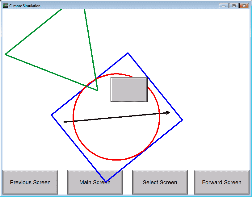
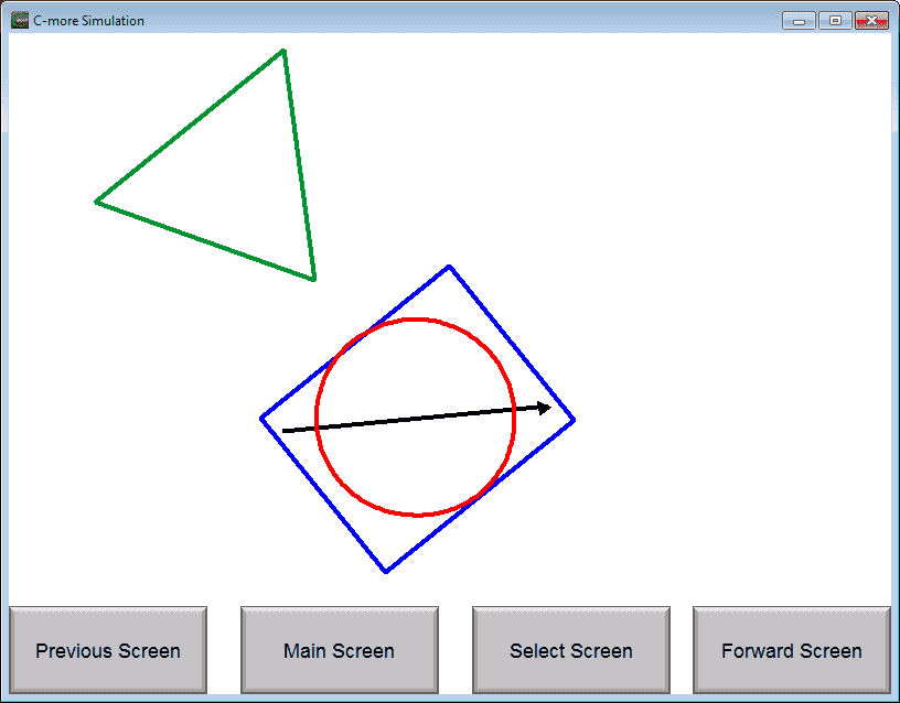
Simulate our C-More Object Shapes Project
We can use the simulator that we discussed last time to view, move and size our object shapes.
PLC Program Additions
Using the program we previously developed, we will add five new rungs to control the visibility of the objects that we have just created.
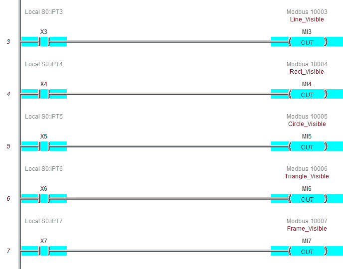
We selected that the Modbus output bit must be ON so that the Object is visible on the screen. So when the output is OFF, the object will be invisible.
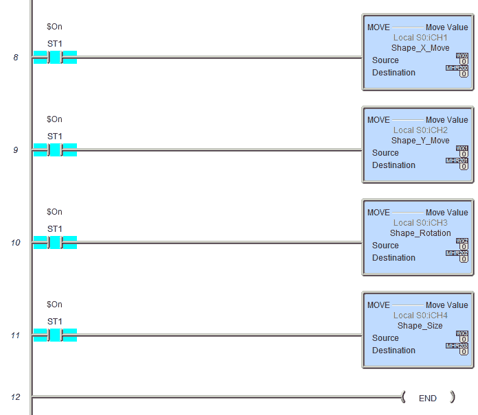
The following WX0 to WX3 registers will control the X, Y, Rotation movement and Size of the objects. This is done through the Modbus Addresses MHR200 to MHR203.
Download the PLC and C-More program here.
Watch the video below to see the Object Shapes in action on our C-More EA9 HMI Panel.
C-More EA9 Panels from Automation Direct
https://www.automationdirect.com/c-more/home
C-More – Graphic Panel (EA9 Series) User Manual and Quick Start Guides
https://cdn.automationdirect.com/static/manuals/ea9userm/ea9userm.html
EA9-T10CL C-More Specifications
https://cdn.automationdirect.com/static/specs/ea9t10cl.pdf
C-More EA9 Programming Software (Current Version V6.42)
https://support.automationdirect.com/products/cmore.html
This software will enable you to program all of the C-More EA9 HMI units. It includes a simulator for your application.
Next time we will look more at the object list buttons that we can do in the C-More HMI Panel.
Watch on YouTube: C-More EA9 HMI Series Panel Object List Shapes
If you have any questions or need further information please contact me.
Thank you,
Garry
If you’re like most of my readers, you’re committed to learning about technology. Numbering systems used in PLC’s are not difficult to learn and understand. We will walk through the numbering systems used in PLCs. This includes Bits, Decimal, Hexadecimal, ASCII and Floating Point.
To get this free article, subscribe to my free email newsletter.
Use the information to inform other people how numbering systems work. Sign up now.

The ‘Robust Data Logging for Free’ eBook is also available as a free download. The link is included when you subscribe to ACC Automation.