Many questions come from serial communications using the Click PLC. Most of these questions deal with communication timing when using multiple send-and-receive instructions. We will show you how to deal with serial communication timing in the Click PLC.
Receive and Send instructions will allow you to send and receive serial data to an external device. The communication method that you set up can be ASCII or Modbus. ASCII (American Standard Communication for Information Interchange) can send to devices such as printers. Receiving ASCII can be used for connecting barcode scanners to the PLC. The barcode will be read as an ASCII string in the PLC. Modbus serial communication (Modbus RTU) is a standard protocol in many automation devices.
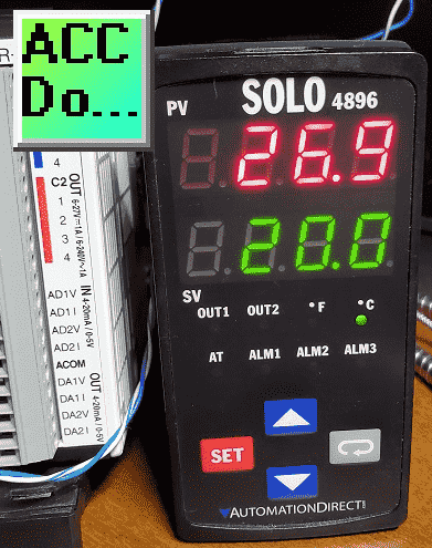
We will demonstrate the Send and Receive instruction by communicating Modbus RTU to a Solo Temperature Controller. Parameters from the Solo process temperature controller will be read using multiple receive instructions. The send instruction will be used multiple times to set the Set Value (SV) and Limits of the SV value entered in the temperature controller. The set values will only be changed when required. Let’s get started.
Our entire Click series can be found here. All the previous information for the Click PLC can be applied to the Click PLUS.
Previously we looked at the following:
Software Installation – Video
Click Software Establish Communication – Video
MQTT Communication – Video
Data Logging – Video
Click Plus Real-Time Clock – Video
The programming software and manuals can be downloaded from the Automation Direct website free of charge.
Watch the video below to see the serial communication timing between the Click PLC and the Solo process temperature controller.
Click PLC RS485 Setup
The first thing that we will do is set up the communication port on the Click PLC. We are using Port 3, which is the serial RS485 port.

Main Menu | Setup | Com Port…
This will call up the communication port settings on the Click programming software.
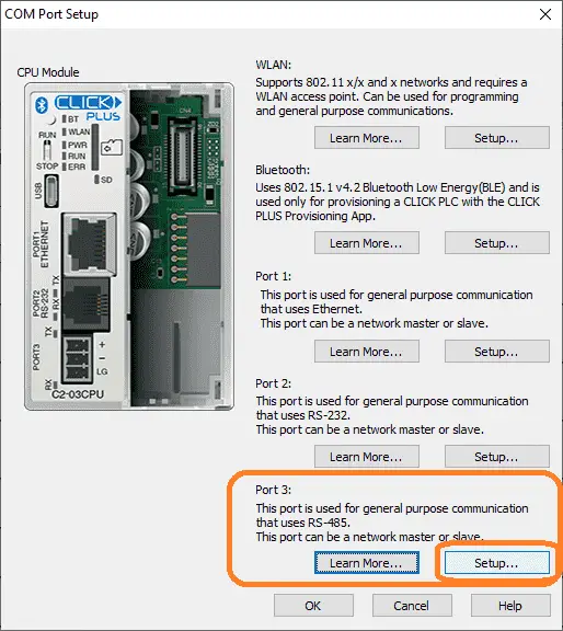
Depending on the Click CPU you use, you may have different versions of this screen. Select the setup button for Port 3 (RS485).
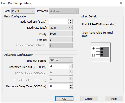
The Com Port Setup Details window will now be displayed. Port3 is the one we selected, and the protocol is set for Modbus. Under the basic Configuration, we will set the baud rate, parity, stop, and data bits.
Note: These parameters must match what is set on the Solo process temperature control, or communications will not occur.
Solo Temperature Controller RS485 Setup
We will now set up the Solo process temperature controller. This needs to be set up before we can communicate with it.
The default setting is ‘Off” for the Online Configuration. (Communication) Here is the way to change into the different modes in the Solo.
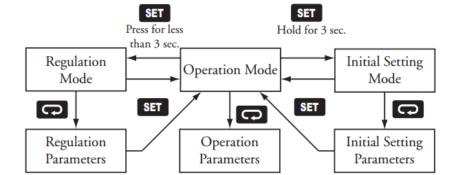
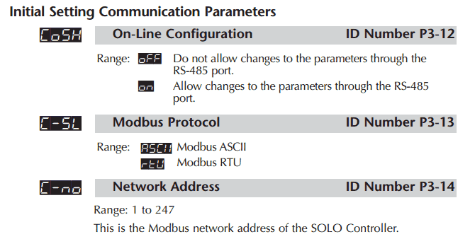
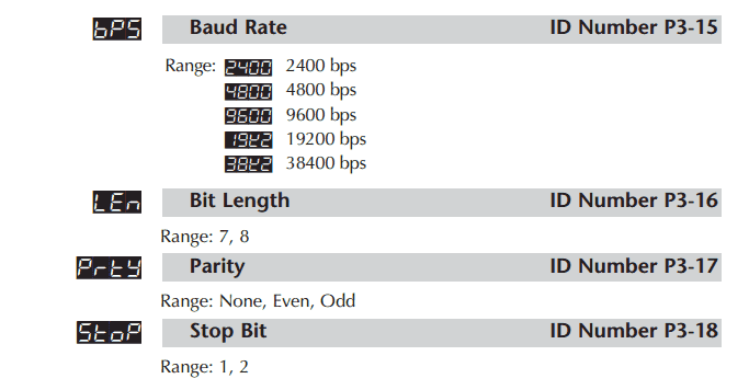
In the Initial Setting Mode, we will change the online configuration to on and make the changes to the Modbus settings as follows: 9600 Baud, Even, 7 Data Bits, 1 Stop Bit, Modbus RTU Format. We will leave the default unit number as 1.
Our controller is now set to communicate.
Download the documentation, Configuration, and monitoring software here.
Click on Solo RS485 Wiring Diagram
RS485 is a serial data transmission standard widely used in industrial automation controls. This twisted wire allows communication with several devices back to one controller. In our case, the Click PLC will be the master, and the Solo temperature controller will be the slave device.
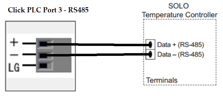
Note: We set the Click and Solo with a node address value of 1. Since the Click will initiate all messages (Master), the node address is not used in the Click.
We can have 32 devices in our Modbus RTU network, including the master. The maximum cable length is 1200m (4000 feet) without repeaters. The transmission rate depends on the wire and length. Longer wire runs require slow transmission (baud rate). If you suspect noise on your line, lowering your transmission rate may help you.
Watch the video below to see the network time service on our Click Plus controller.
Slave Modbus Addresses
Modbus is a master/slave protocol. The master sends a request, and the slave will respond to that request only. Addresses in the Modbus device are either 5 or 6 digits long. The Click will use a six-digit Modbus decimal number. Here is the Modbus addresses that we will use in our sample program.
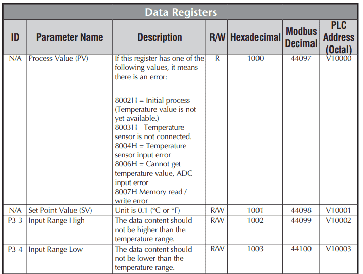
The process value, setpoint, input range high, and input range low values will be read. Modbus addresses starting at 404097 to 404100 will be read. The beginning digit 4 gives a reference to the Modbus Holding Registers. See the links below for further information on Modbus.

This will demonstrate multiple reads in the PLC. P, I, D, and the offset parameters will also be read into the Click PLC. These addresses start at 404106.
We will also write the setpoint value and input range values. This is possible because of the R/W indication, meaning read and write.
Watch the video below to see the Modbus addresses being read and written in action on our Click Plus controller.
Click PLC Serial Port Programming
Our Click serial program will use two Receive Instructions to read the above parameters in the PLC. It will also use two Send Instructions to write the setpoint value and input limits. The writes will only happen when an internal signal is given in the PLC. So we will constantly be reading until a write is required. This is a suitable method so we can directly control the PLC/HMI or Solo.
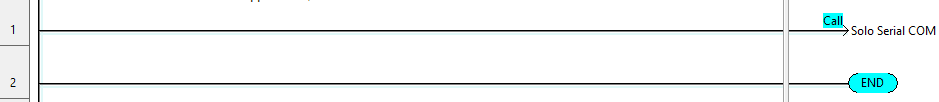
Our Solo serial communication will be in a separate subroutine called every scan. This is just for organization and readability purposes. The program will also work in the main program.
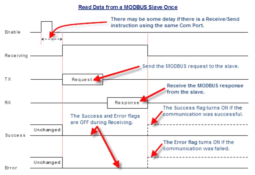
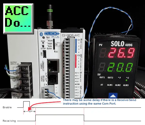
Here is the timing chart for the receiving instruction of the Click.
The enable will be a one-shot, leading-edge trigger. Since we are not using any other Receive or Send instructions on Port 3 simultaneously, we will not have a delay.
We have three signals, receiving, success and error. Once we are not receiving, then we can look at the success and error signals.
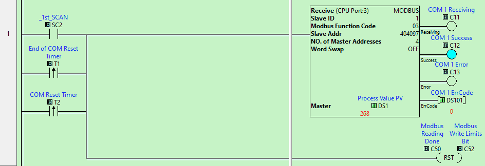
The first scan of the PLC, end of communication timer, or communication reset timer will start our reading of the Modbus address 404097. We will read four consecutive addresses and place them in the PLC memory starting at DS1.
Communication flags (COM 1) receiving, success and error are then used for the next read instruction.
The reset is used for the sequencing bits for our communication.
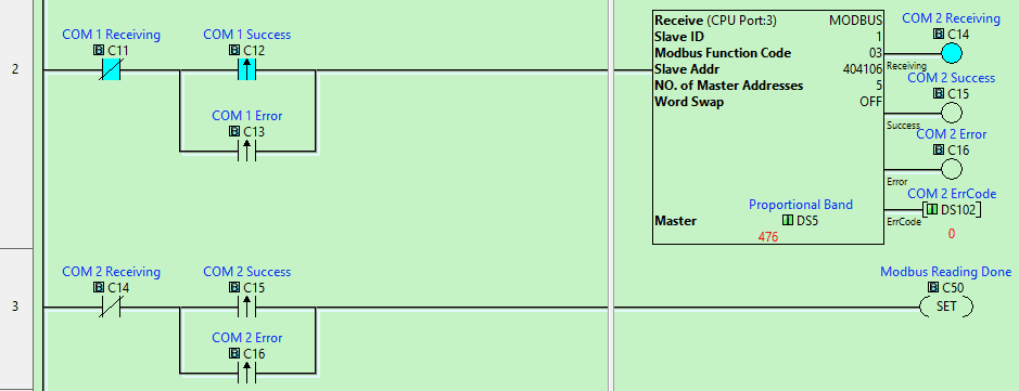
The COM 1 not receiving a bit with the leading edge (one-shot) for the COM 1 success or error will trigger the next read instruction.
COM 2 not receiving along with the leading edge of the success or error will set the Modbus reading done a bit.
We will now write information using the Send instruction in the Click PLC.
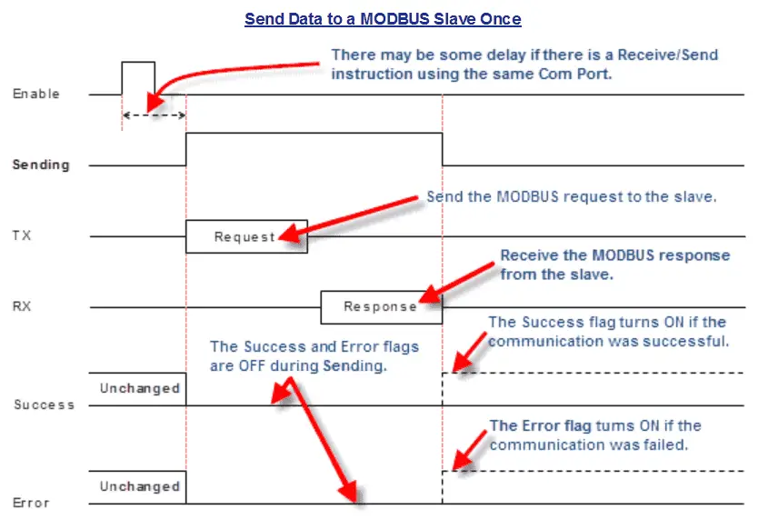
The timing chart for the send instruction is very similar to the receive instruction. We have the same three output bits that can be used in our logic for the communication timing.
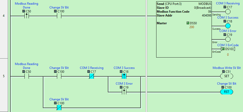
The change set value bit will control if the write operation is executed. If the Change SV Bit is on and the leading edge of Modbus reading is done, the bit will trigger the Send command. This will write the value in DS50 to Modbus address 404098, which is the setpoint value. COM 3 bits are then set.
Rung 5 will look for the COM 3 bits, set the Modbus to write SV bit, and reset the Change SV Bit. If the Change SV bit is off, then the Modbus wire SV bit is set, and the Change SV bit is immediately reset.
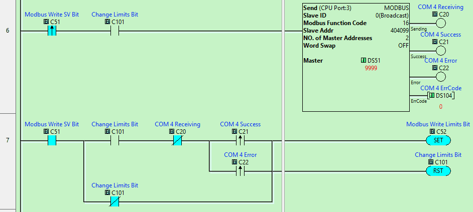
This program will then cascade to the next write operation. Follow the logic that is similar to the above. The change limits bit will control if the information is sent or not.
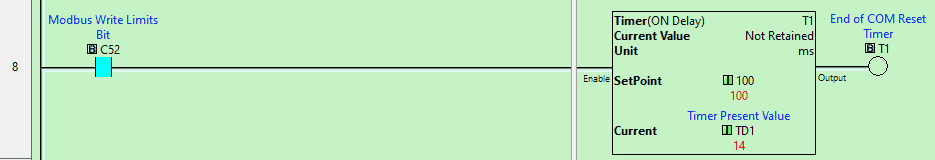
Once the write limits are complete, a timer delay of 100 milliseconds is used. This will allow the change for the write bits to be set on with the software.
The output for the timer will then start the communication over again. Even with this slight delay, we are reading/writing the data from the Solo about five times per second.
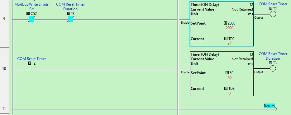
The last two rungs set up the overall reset of the communication. The timers, when expired, will start the communication again. This is necessary if a cable gets unplugged or you use online programming.
Watch the video below to see the serial communication timing in action on our Click Plus controller.
Download the Click PLC program here.
Click PLC Support Links
The Click PLC can be programmed using free Click programming software from Automation Direct. Here is a link to the software.
Version 3.00
Version 2.60
The entire Click PLC series before the Click PLUS release can be found here.
All previous posts and information are still valid with the Click PLC line-up.
YouTube Click Playlist
YouTube Click PLUS Playlist
Click and Click PLUS PLC Overview
Click and Click PLUS PLC Videos from Automation Direct
Modbus Learning Links:
Simply Modbus Frequently Asked Questions
Modbus TCP/IP Overview – Real-Time Automation
All You Need to Know About Modbus RTU – Video
Watch on YouTube: Click PLC Serial Communication Timing
If you have any questions or need further information, please contact me.
Thank you,
Garry
If you’re like most of my readers, you’re committed to learning about technology. Numbering systems used in PLCs are not challenging to learn and understand. We will walk through the numbering systems used in PLCs. This includes Bits, Decimals, Hexadecimal, ASCII, and Floating Points. To get this free article, subscribe to my free email newsletter.
Use the information to inform others how numbering systems work. Sign up now. The ‘Robust Data Logging for Free’ eBook is also available as a free download. The link is included when you subscribe to ACC Automation.
I am going to set up a click PLC that will read several Solo PIDs and write new set values when a new one is entered from an CMore Micro or through programmed decrements. Would it be best for me to use a subroutine for each Solo PID?
Hi John,
Since all of the communication will be through the RS485 port, I would just use one subroutine. This would handle the timing for all the communications to the Solo controllers.
Regards,
Garry
Thanks, very helpful. One point of clarification, since I will be switching between Solo PIDs as different slave IDs, would it be better to use a different set of End Com, Com Reset & Com Delay timers for each different device to avoid errors on read/write to the next device?
Hi John,
Since the Click PLC will be the master, it will control when the communication happens to the slaves.
It should not be necessary to add extra timer delays. I have used the Click to control 8 different Solo controllers on an extruder line.
The PV of the Solo is constantly read, and writing the SV happens only when required.
Regards,
Garry