A lot of times when programming a PLC you need to track what has previously happened. Shift registers allow you to do just that. The Click PLC has a shift register in the instruction set. We will discuss the shift register and look at an example.
Previously in this series we have discussed:
System Hardware – Video
Installing the Software – Video
Establish Communication – Video
Numbering System and Addressing – Video
Timers and Counters
– Counter Video
– Timer Video
Compare and Math Instructions – Video
Program Control Instructions – Video
The programming software and manuals can be downloaded from the Automation Direct website free of charge.
Click PLC Shift Register Instruction
The shift register instruction will move a range of consecutive bits. This movement is controlled by the clock input bit which will trigger with each transition from off to on. The bits continually shift with the clock pulse until the end bit number. When the bit shifts past the last bit number then the bit information is lost. The data input will put a ‘1’ or a ‘0’ in the first bit of the shift register. (Note: We can also put bits on anywhere within the shift register.) Reset input will clear the shift register by putting a ‘0’ in each of the bits in the range.
Example: Shift Register Movement
0000111100001111
After the first clock pulse:
0001111000011110
After the second clock pulse:
0011110000111100
After the third clock pulse:
0111100001111000
After the fourth clock pulse:
1111000011110000
After the fifth clock pulse:
1110000111100000
etc…
Click Shift Register Instruction
Let’s look at the Click PLC Shift Register instruction.
The shift register in the click PLC will use the control bits. (C1 to C2000) So the maximum amount of bits that can shift will be 2000 bits.
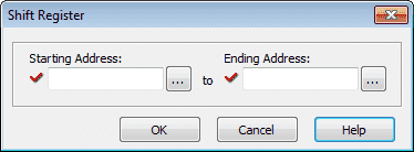
Starting Address – This is the beginning bit of the shift register
Ending Address – This is the last bit of the shift register
Note: If the ending address is larger than the starting address, then the bits will shift from the starting to the ending address. If the ending address is smaller than the starting address, then the bits will shift from the ending to the starting address.
The click PLC shift register has three inputs to the instruction.
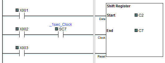
Data Input – This will turn on or off the first bit of the shift register when the clock pulse input transitions from off to on.
Clock Input – This is the input that will shift the bits in the shift register on a transition from off to on. In a typical application such as a conveyor belt, this would be the sensor to detect the speed of the conveyor belt.
Reset Input – The input will turn all of the bits in the shift register off. (0)
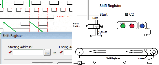
Here is the timing chart from the help menu of the Click Programming Software.
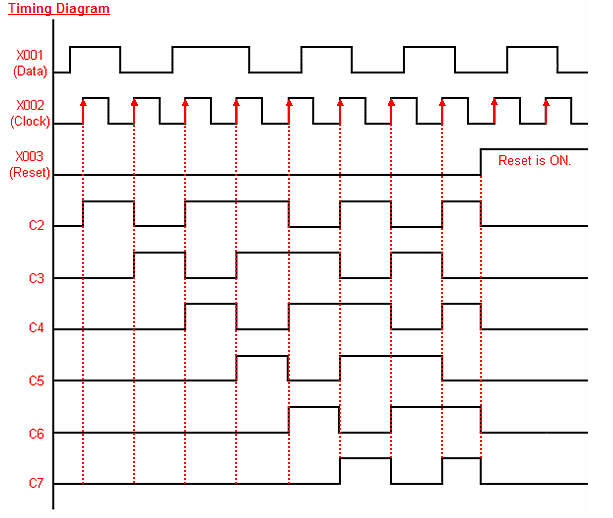
The inputs are listed on the left of the table. To the right is the difference in time.
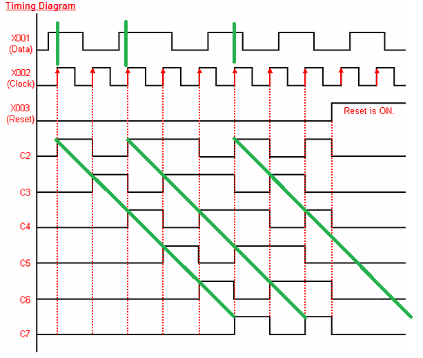
Green lines have been added so you can see that as time goes by with the clock bit, C2 information will get shifted to the next position C3. This shifting continues with the clock input until the last bit in the shift register. The bit status is then lost after the last bit gets shifted.
Adding Additional Inputs to a Shift Register
Adding additional inputs (Data) to the shift register is possible. If there are two locations that inputs can be added then the following ladder can be used.

Input X5 will turn on C4 or if C4 is already on it will remain on. The clock input will then shift the bits from this location like the data input of the shift register.
Controlling Outputs from the Click Shift Instruction
The bits can be used at any time of the shift register. We do not have to use the end bit only. Also, multiple bits can be used if several operations need to be done. The following is an example of turning on an output when the shift register bit is on.
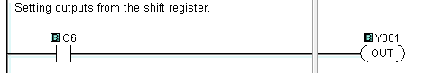
Click Shit Register Instruction Sample Program
So what can we do with these bits that are moving within the range? A typical example is to track items along a conveyor belt.
https://accautomation.ca/plc-programming-example-shift-register-conveyor-reject/
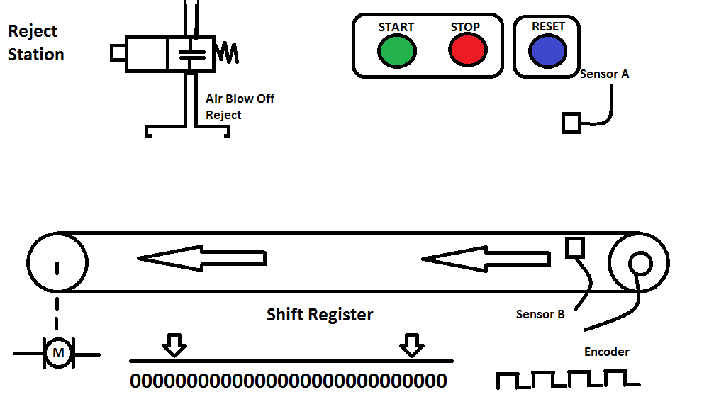
A start pushbutton (NO) is used to start the conveyor and a stop pushbutton (NC) is used to stop. Sensor B detects a product on the conveyor belt and sensor A will detect if it is too large and needs to be rejected. (Shift Register Input) The product is tracked along the conveyor belt and when under the reject station the Reject Blow Off will expel the bad product. The product is randomly placed on the conveyor belt, so an incremental encoder is used to track the conveyor movement. (Shift Register Clock) The reset pushbutton (NO) will signal that all of the product on the conveyor has been removed between the sensors and reject blow-off. (Shift Register Reset)
Another application would be to track if the product has fallen off of the conveyor belt. A sensor would be used at the other end in conjunction with the shift bits to determine if the product is still on the conveyor belt.
Next time we will look at drum instruction.
Watch on YouTube: Click PLC Shift Register Instruction
If you have any questions or need further information please contact me.
Thank you,
Garry
If you’re like most of my readers, you’re committed to learning about technology. Numbering systems used in PLC’s are not difficult to learn and understand. We will walk through the numbering systems used in PLCs. This includes Bits, Decimal, Hexadecimal, ASCII and Floating Point.
To get this free article, subscribe to my free email newsletter.
Use the information to inform other people how numbering systems work. Sign up now.

The ‘Robust Data Logging for Free’ eBook is also available as a free download. The link is included when you subscribe to ACC Automation.
Hey Mr. Gary. I’m having an error come up when I try the shift instruction on the CLICK software. It is saying there is no contact for the clock input.
Hi Shaun,
The shift instruction on the click uses three conditions. Sometimes when the rung is not connected to the instruction this error will occur. Position your cursor to the right-hand side of the input condition for the clock. Hit and hold control and then the right arrow. This will draw a line to the end of the rung. This should be lined up with the clock input of the instruction.
I hope this helps you out.
Let me know.
Thanks,
Garry