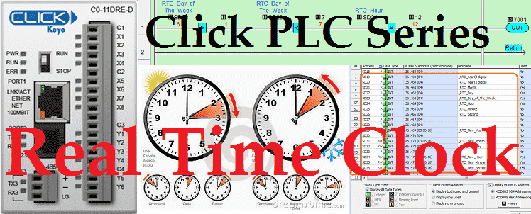
The click plc has a real-time clock that will allow us to control outputs based on a date or time of day. This real-time clock (RTC) can be set from the click programming software or through the program of the controller. Our programs in the click can use the following calendar and clock values:
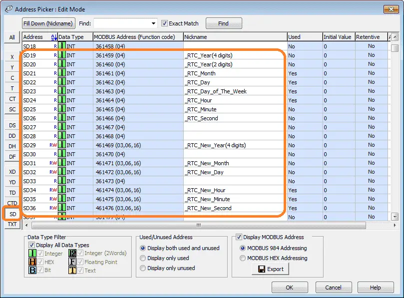
SD19 – RTC Year – 4 digits (2021)
SD20 – RTC Year – 2 digits (21)
SD21 – RTC Month – (00 to 12)
SD22 – RTC Day – (00 to 31)
SD23 – RTC Day of the Week – 1 Sunday to 7 Saturday
SD24 – RTC Hour – (00 to 23)
SD25 – RTC Minute – (00 to 59)
SD26 – RTC Second – (00 to 59)
We will be using the RTC – Real Time Clock in a sample program. This program will turn on an output Monday to Friday from noon until 1 pm. It will also adjust for daylight savings time. Let’s get started.
Previously in this series, we have discussed:
System Hardware – Video
Installing the Software – Video
Establish Communication – Video
Numbering System and Addressing – Video
Timers and Counters
– Counter Video
– Timer Video
Compare and Math Instructions – Video
Program Control Instructions – Video
Shift Register – Video
Drum Instruction – Video
Send and Receive Instructions – Video
AdvancedHMI Communication – Video
Firmware Update – Video
HMI Rotary Encoder Dial Input – Video
High Speed Counters Part 1
– High-Speed Count Mode Video
– Interval Measurement Mode Video
– Duration Measurement Mode Video
– Frequency Measurement Mode Video
High Speed Counters Part 2
– External Interrupt Mode Video
– Pulse Catch Mode Video
– Filter Pulse Mode Video
– Frequency Measurement and High-Speed Count Mode Video
Wiring Stack Light to Click PLC – Video
Wiring Push Buttons and Selector Switch to Click PLC – Video
– Test and Assembly of Push Buttons and a Selector Switch – Video
Wiring an Inductive Proximity NPN PNP Sensor to the Click PLC – Video
Wiring a Capacitive Proximity NPN PNP Sensor to the Click PLC – Video
Wiring an Ultrasonic Proximity Sensor to the Click PLC – Video
– Unboxing our UK1F Ultrasonic Proximity Sensor – Video
Analog Dusk to Dawn Program – Video
PID using Factory IO – Video
PID Instruction and Autotuning using Factory IO – Video
Logging Data with Time and Date Stamp – Video
Stride Field Remote IO Modules Modbus TCP Ethernet
– Unboxing SIO MB12CDR and SIO MB04ADS Video
– Powering and Configuring Video
Click PLC to Stride Field IO Modbus TCP – Video
Modbus RTU TCP Remote IO Controller BX-MBIO
– BX-MBIO Hardware Video
– BX-MBIO Powering and Configuring Video
Click PLC to Modbus TCP RTU Remote IO Controller BX-MBIO – Video
Modbus ASCII Protocol – Video
Our entire series can be found here.
The programming software and manuals can be downloaded from the Automation Direct website free of charge.
Watch the video below to see our Click PLC controller program control an output based on the real-time clock and adjust automatically for daylight savings time.
Click PLC Hardware
The Real-Time Clock/Calendar is available on all of the Click PLC’s except for the four basic models. These models start with part number C0-00.
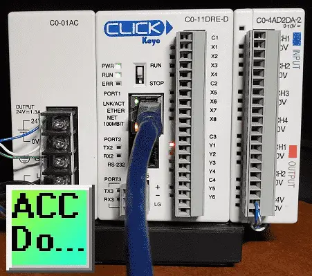
We will be using our model C0-11DRE-D Ethernet click unit.
RTC – Real Time Clock Memory Areas
The click PLC uses the SD and SC areas to control and view the real-time clock.
The SD area will allow us to read the RTC and set new values.
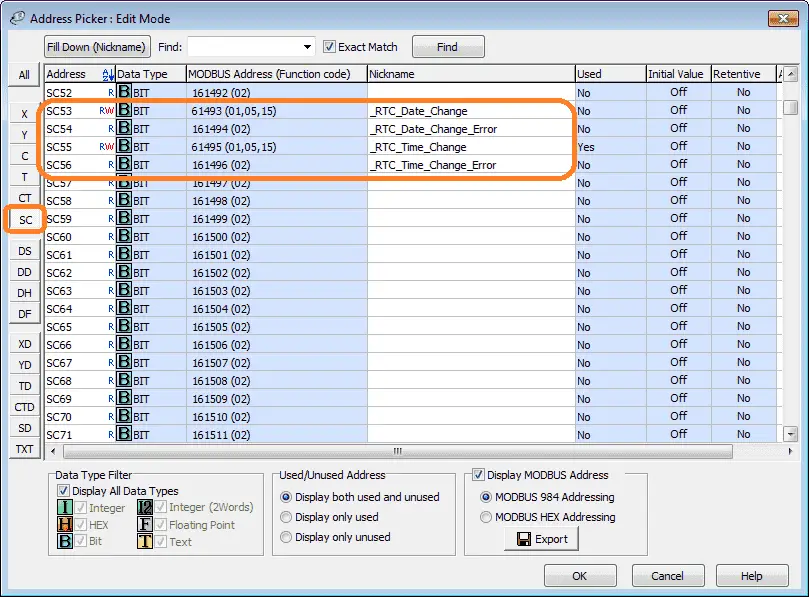
The SC area will allow us to write a new calendar or clock values into the RTC.
The specification for the RTC in the CLICK C0-1x series is a possible drift of 100s per month. Additionally, the cycle for updating RTC data to the SD register is 1s. Therefore, there is an error of 1s ± 1s in the timing of the display of data in the SD Register.
Typically I have seen +/- 15 to 30 seconds per month.
Note: Modbus addresses have been included. The setting of the values could be done over a network.
Click PLC Programming Software – Changing the RTC
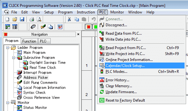
Once you are online with the click PLC using the programming software, call up the calendar/clock setup. (Main menu | PLC | Calendar/Clock Setup…)
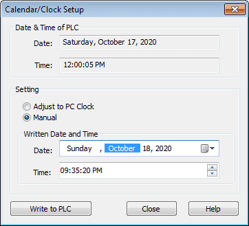
The calendar/clock set up window will allow you to change the date and time to either adjust to the PC Clock or manually enter the values. Once the values have been entered or the Adjust to PC Clock has been selected click the Write to PLC button. This will automatically update the RTC in the connected PLC.
Select close to close this window.
Sample Click PLC Program
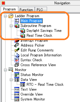
Our sample program will contain two subroutines. Real-Time Clock and Daylight Savings Time. Our real-time Clock subroutine will turn on and output Monday to Friday from noon until 1:00 PM this will control the active lights in a lunchroom. Our daylight savings time subroutine will control the DST which begins at 2:00 AM local time on the 2nd Sunday in March and on the 1st Sunday in November they will return to 2:00 AM local time. When daylight savings time begins, your clocks will move ahead one hour.
Program Using the RTC – Real Time Clock
![]()
The first line of code in our main program we’ll call the real time clock subroutine.
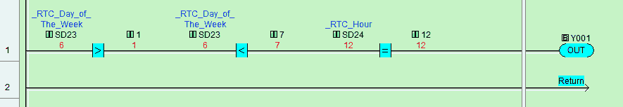
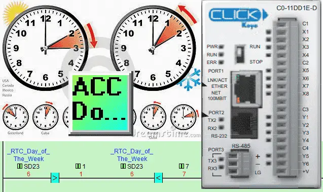
When programming the RTC, we use the compare instruction. We want our output to be on Monday to Friday from noon until 1 pm. Using the RTC Day of the Week (SC23) we compare our current day to see if it is greater than 1 (Sunday) AND less than 7 (Saturday). Since we want the output to be on for one hour we compare the RTC Hour (SD24) to the value of 12. The hour register is a military 24-hour clock. As soon as the hour changes from 11 to 12 this will turn on and turn off when the hour changes to 13. The output Y1 will be on when these conditions are met.
Return instruction will return to the main program.
Adjusting Daylight Savings Time
When does it start and end?
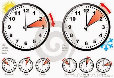
Canada Daylight Saving Time begins at 2:00 am local time on the second Sunday in March. On the first Sunday in November areas on Daylight Saving Time return to Standard Time at 2:00 am local time. When Daylight Saving Time begins, turn your clocks ahead one hour. This is what happens in most parts of Canada.
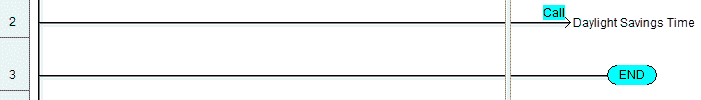
Our main program will call up our daylight savings time subroutine.
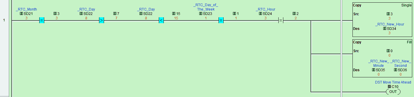
The first line of code will check for the 3rd month (March). Then ensure that the day is between 8 and 14 so that we are viewing the second week. Next, make sure the day of the week is 1 (Sunday). Finally, it will check to make sure the hour is 2 (2 am). The value of 3 is placed in the RTC new hour and 0 is placed in the RTC new minutes and seconds. Bit C10 is then turned on to indicate that a time change is required.
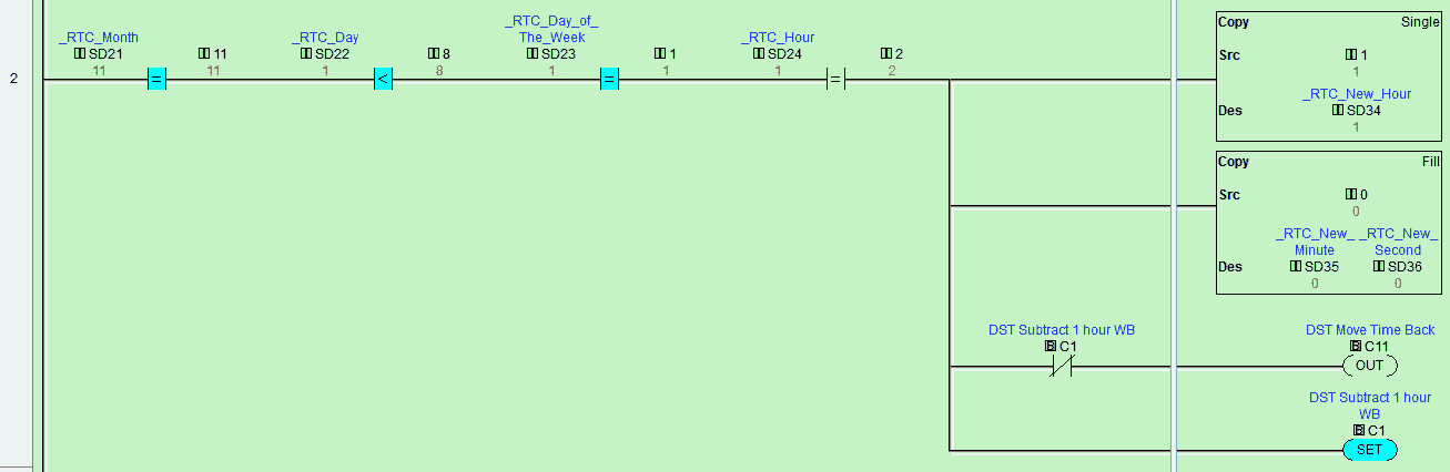
The second line of code will check for the 11th month (November). Then ensure that the day is less than 8 first week. Next, make sure the day of the week is 1 (Sunday). Finally, it will check to make sure the hour is 2 (2 am). The value of 1 is placed in the RTC new hour and 0 is placed in the RTC new minutes and seconds. Bit C11 is then turned on if C1 is not set, to indicate that a time change is required. We also set a bit C1. This is important because we do not want to continually move the clock back 1 hour. This should only happen once per year.
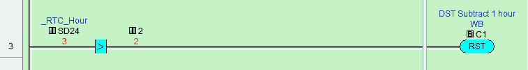
When the RTC Hour is greater than 2 we will reset the C1 bit indicating that we have completed the fallback of 1 hour.
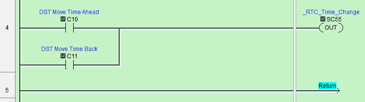
When the signals to move ahead (C10) and move back (C11) one hour are on then the RTC time change bit (SC55) will be turned on. This will then set the time that we have put in the registers.
The return instruction will return to the main program.
Monitoring the RTC – Real Time Clock
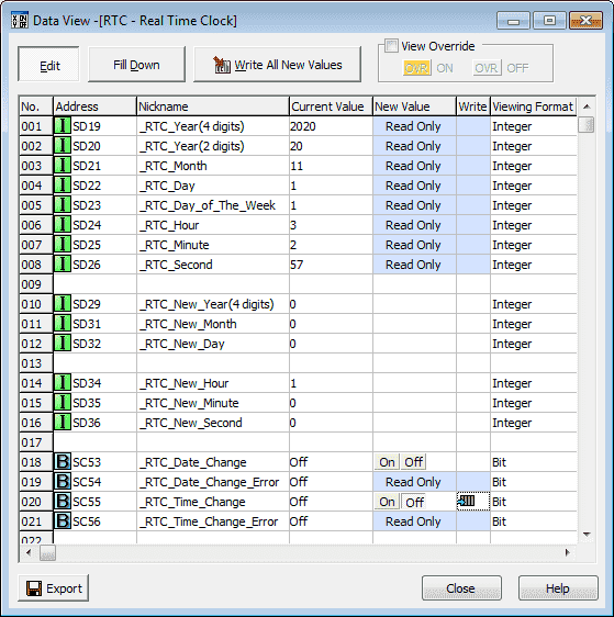
Using the data view, we can monitor the values of the RTC registers and bits.
Watch the video below to see the operation of our real-time clock and adjustments for daylight savings time on our Click PLC Controller.
Download the Click PLC program here.
Click PLC Support Links
The Click PLC can be programmed using free Click programming software from Automation Direct. Here is a link to the software.
https://support.automationdirect.com/products/clickplcs.html
The following links will help you to install the software and establish communication.
https://accautomation.ca/click-plc-installing-the-software/
https://accautomation.ca/click-plc-establish-communication/
The entire Click PLC series can be found at the following URL:
https://accautomation.ca/series/click-plc/
Watch on YouTube: Click PLC Real Time Clock
If you have any questions or need further information please contact me.
Thank you,
Garry
If you’re like most of my readers, you’re committed to learning about technology. Numbering systems used in PLC’s are not difficult to learn and understand. We will walk through the numbering systems used in PLCs. This includes Bits, Decimal, Hexadecimal, ASCII and Floating Point.
To get this free article, subscribe to my free email newsletter.
Use the information to inform other people how numbering systems work. Sign up now.

The ‘Robust Data Logging for Free’ eBook is also available as a free download. The link is included when you subscribe to ACC Automation.