In the current era of automation and digitization, Programmable Logic Controllers (PLCs) have emerged as integral components for varied industries, including manufacturing, construction, and more. Mastering the PLC and what you need to know involves different facets of the PLCs. Understanding their basics to troubleshooting common concerns is crucial in optimizing their efficiency and application. This aims to provide a panoramic view of PLCs, starting with a rudimentary understanding of their structure and components, investigating their operational machinations and applications, exploring the central role of ladder logic in PLC programming, and finally, touching on effective troubleshooting and maintenance techniques for prolonged service. Let’s get started!
Understanding the Basics of a PLC
Understanding Programmable Logic Controllers (PLCs)
Programmable Logic Controllers (PLCs) are industrial digital computers modified to control manufacturing processes such as assembly lines or robotic systems. These computers are designed for special tasks and can withstand harsh environments, making them excellent choices for heavy-duty industrial applications.
A Brief History of PLCs
The history of PLCs dates back to the late 1960s, providing an industrial control solution that was more efficient than traditional relay control systems. When industries started using solid-state devices in manufacturing, the concept of programmable controllers emerged. The first PLC, the Modular Digital Controller (MODICON), was developed and introduced by Richard Morley in 1968.
Basic Structure and Components
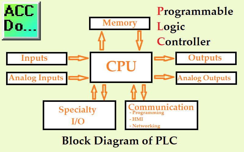
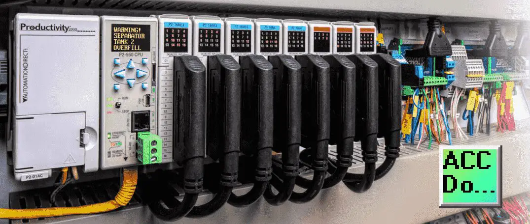
At its core, a PLC consists of a Central Processing Unit (CPU), input and output modules, memory, and a power supply.
Central Processing Unit (CPU)
The CPU is the brain of the PLC, where all the computing and logic operations occur. It communicates with the rest of the system, processes the information, and controls the other components within the PLC.
Input and Output Modules
These modules allow the PLC to interface with the devices it is controlling. The input modules receive signals from input devices like sensors, switches, and meters. These signals might represent temperature, pressure, levels, or other important monitoring variables. The output modules transmit signals to control devices such as actuators, motors, pumps, lights, or other items that perform physical actions based on the program’s directions.
Memory
The memory of a PLC is used to store the user program and the data or status of the input and output devices. The CPU processes the input signals based on the user program stored in memory and executes output signals.
Power Supply
The power supply is a crucial component that provides the necessary electrical power for the operation of the PLC system. It converts the plant’s power source into a form acceptable to the PLC’s circuits. The PLC power supply also isolates the PLC internal circuits from industrial power lines to protect against voltage spikes and fluctuations.
The essentials of PLC, including its historical context, fundamental structure, and principal components such as the input and output modules, CPU, memory, and power supplies, are integral to gaining a full understanding. This knowledge serves as the bedrock of industrial control systems.
How PLCs Work and Their Applications
Demystifying the Core Functions of a PLC
In industrial settings, a digital computer known as a Programmable Logic Controller, or simply PLC, controls machines and processes. It applies a programmable memory to execute functions ranging from logic sequencing and timing to arithmetic and counting, hence controlling myriad operations of an industrial machine.
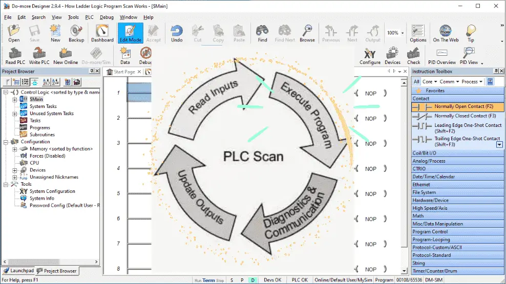
The operation of a PLC revolves around four fundamental stages: scanning of inputs, executing programs, diagnostics & communication, and updating of outputs. Initially, in the ‘input scan’ stage, the PLC assesses the condition of the inputs, sensors sending signals, to be specific. During the following ‘program scan’ stage, it puts the previously written control program in its memory into action. Diagnostics will ensure that PLC memory and devices are working correctly. Communication will be handled to other devices or within the controller itself. Lastly, at the ‘output scan’ stage, it updates the outputs’ conditions depending on the operational inputs and the program embedded in its memory. Scanning happens cyclically, meaning this operation happens several times per second.
Different Types of PLCs
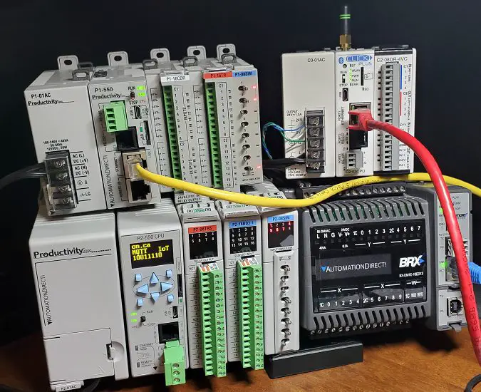
PLCs come in various forms and sizes but can be broadly categorized into modular and compact (brick) PLCs.
As their name suggests, modular PLCs have different modules that can be coupled to create a custom-tailored controller. Each module is responsible for a specific function, such as Input/Output (I/O) handling or communication.
Compact PLCs, on the other hand, have fixed I/O points and lack the flexibility of a modular PLC. However, they are generally smaller, easier to program, and cost-effective for smaller automation tasks.
Exploring the Versatility of PLCs in Various Industries
Programmable Logic Controllers (PLCs) stretch across various fields, from automated solutions to manufacturing and construction industries. Their ability to navigate complex operations is invaluable in these sectors.
In the realm of manufacturing, one can observe PLCs controlling assembly lines. They efficiently manage the initiation, coordination, execution, and surveillance of various stages in the production cycle. From filling bottles in a beverage factory to directing precise movements on automotive assembly lines, PLCs underpin these processes.
Extending beyond manufacturing, the construction industry also benefits greatly from the introduction of PLCs. Equipment such as cranes and drills function under the regulation of PLCs, thereby enhancing safety, augmenting productivity, and streamlining the overall construction process.
Furthermore, PLCs have found their way into our homes, integrated into everyday appliances like washing machines and dishwashers. Beyond that, they manage traffic light systems, elevator controls, and building automation setups, especially for regulating heating, ventilation, and air conditioning (HVAC) systems.
In essence, PLCs simplify the management of intricate operations across various industries, significantly boosting productivity, enhancing the quality of final products, and minimizing issues like machine downtime and human error.
Ladder Logic in PLC Programming
Delving into PLC Programming via Ladder Logic
A Programmable Logic Controller (PLC) is a specialized computer primarily used in numerous industrial automation applications. They are fashioned to endure harsh environmental conditions while controlling multifaceted functions reliably and flexibly. One primary tool used in programming these PLCs is a technique known as ladder logic.
Symbols and Structure in Ladder Logic
The fundamental components of ladder logic are symbols representing various instructions. These symbols are organized into rungs, and the entire arrangement of rungs is known as a ladder diagram.
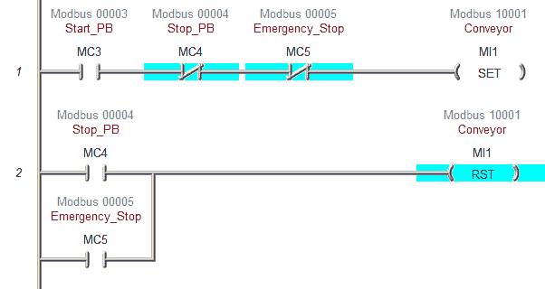
You need to be familiar with several symbols to understand ladder logic. The most basic symbols are contacts and coils, representing inputs and outputs. Contacts can be normally open (NO) or normally closed (NC), representing the different states of an input. Coils represent outputs and show the state of an output – such as whether a component is off or on.
Another essential concept in ladder logic is the power rail, represented by vertical lines on either side of the ladder diagram. Input contacts are wired from the left power rail and output contacts are wired to the right power rail.
Practical Application of Ladder Logic in PLCs
Understanding how ladder logic applies in real-world applications can be best illustrated by examples. Let’s take an example of an automated garage door:
- The door should open when a button is pressed (Input 1) but only if the door is fully closed (Input 2).
- The door should close when a button is pressed (Input 3) but only if the door is fully open (Input 4).
A ladder logic diagram would represent these requirements in the PLC. Inputs 1 and 2 symbols would be connected in series on the first rung to control the ‘door open’ output coil. Inputs 3 and 4 symbols would be connected in series on the second rung to control the ‘door close’ output coil.
That’s a very simple example, but ladder logic can be used for much more complex control systems, including those that control industrial processes, manufacturing lines, and various automated systems.
The Significance of Ladder Logic in PLC Programming
Ladder Logic is widely recognized and implemented in PLC programming. One of its main advantages is its visual aspect, which simplifies the representation of complex control logic in an easily comprehensible manner. Compared to other programming languages, it’s simpler to understand and less complex to troubleshoot. This is primarily because Ladder Logic aligns closely with the design and comprehension of physical control circuits, making it a familiar tool for those with electrical or industrial engineering backgrounds.
Troubleshooting and Maintenance of a PLC
A Deeper Dive into Programmable Logic Controllers
A Programmable Logic Controller (PLC) is an industrial computer customized for controlling manufacturing processes. This includes assembly lines, robotic devices, and other activities requiring high-reliability control, simplified programming, and efficient fault diagnosis during processes. Initially developed as a replacement for relay circuits, PLCs have evolved, emerging as the core component of any automated industrial process. Despite their durability and reliability, PLCs, like any other technological device, are susceptible to issues that could potentially disrupt a production line, requiring efficient troubleshooting to resume normal operations.
Common Problems
Maintenance staff typically encounter several common problems with PLCs. One common issue is that I/O modules are not responsive or faulty. This problem may stem from physical damage to the module or a defective CPU, among other causes. Another common problem is the unresponsiveness of the PLC system, which might be caused by power issues, such as voltage spikes, power outages, or outdated software.
Causes and Solutions
Understanding the root causes of PLC issues is critical to resolving them effectively. One potential cause of I/O module failure could be an overloaded backplane. If modules exceed the power supply’s capacity, you may need to add an additional power supply or reduce the load. Power supply issues might be resolved by adding a battery backup or surge protection.
Another major cause of PLC problems is electrical and radio frequency noise. Electrical noise (from large motors starting and stopping, for instance) can interfere with the PLC’s operation. The best way to prevent this is by separating high-current power lines from the low-current logic lines, using shielded cables, and installing line filters and surge suppressors.
When outdated software causes unresponsiveness, it might be necessary to update the software or even replace the PLC if it is beyond its supported life cycle. This may require contacting the manufacturer or a qualified technician.
Preventive Maintenance
Performing preventive maintenance can help avoid many common PLC issues. This involves regularly testing the PLC functions, keeping spare parts available, cleaning the PLC setup to prevent dust build-up, and ensuring that the PLC environment has suitable temperature and humidity levels. Regular visual inspections can often catch small issues before they become significant problems.
Another preventive maintenance approach involves having the right PLC programming software. Updating the correct software will ensure that the PLC functions are operating as they should.
Training
Finally, since PLCs are sophisticated and crucial equipment, training maintenance staff to handle them properly can save time and money. Maintenance personnel should be adequately trained to identify and rectify common PLC problems, perform routine preventive maintenance tasks, and respond to unusual scenarios or emergencies.
In essence, Programmable Logic Controllers (PLCs) are significant in today’s manufacturing and various industrial processes. However, they can occasionally become a root cause for some operational issues. To ensure the uninterrupted flow of the production line, it’s vital to have a good understanding of common troubles in PLCs, the reasons behind these issues, and their optimal solutions. Investing time in regular preventive maintenance and proper training greatly helps maintain a seamless and durable PLC operation.

The Future of PLCs
Advancements in PLCs: The Step Forward in Technology
Programmable Logic Controllers (PLCs) serve a fundamental purpose in automation and industrial process control. In the last few decades, we have seen substantial growth and evolution in PLCs to adapt to and simplify the progress in industrial applications. PLCs manage various systems and equipment in automation machinery as integral technology components. This is especially true in the manufacturing sector, as well as in numerous other industries.
PLCs and The Internet of Things
IoT integrates physical devices with internet connectivity, leading to a merger of the physical and digital worlds. IoT in PLC systems promises enhanced connectivity, control, and information exchange in industrial processes. It is expected that the PLCs of the future will increasingly incorporate IoT, resulting in more complex intelligence and analytical capabilities.
With IoT-enabled PLCs, industries can expect more seamless integration and data sharing between devices. This allows for real-time monitoring and control over various operational parameters, increasing efficiency and reducing downtime. IoT in PLCs also fosters predictive maintenance, significantly reducing the risks and costs of sudden equipment failure.
Machine Learning’s Impact on PLCs
Machine learning is another key technology expected to transform the future of PLCs. Machine learning systems have the ability to ‘learn’ from data patterns and make autonomous decisions based on this insight. These learning capabilities can facilitate more intelligent process control and anomaly detection when applied to PLCs.
For instance, machine learning-enabled PLC systems can predict potential system anomalies or machinery failures before they happen, enabling a more proactive maintenance approach. Furthermore, autonomously operating PLCs can optimize manufacturing processes by reacting to real-time changes without human intervention.
In various industries such as oil and gas, food and beverage, or energy, machine learning can help improve yield, optimize resource usage, and reduce waste. This can also help businesses become more competitive by improving productivity, efficiency, and flexibility.
Conclusion
PLCs will likely incorporate more sophisticated IoT and machine learning capabilities as technology advances. This integration promises to enhance operational efficiency, decrease downtime, reduce costs, and improve product quality, ushering in a new era of industrial automation. As such, it is crucial for organizations to understand the future trajectory of PLCs and invest in their modernization to stay competitive in a rapidly evolving industrial landscape.
Amid the relentless pace of modern technological advancements, PLCs, too, are bound for evolution. With the rise in the application of new-age technologies such as the Internet of Things (IoT) and machine learning, the way PLCs function and their integration in industries are set to undergo marked transformations. The impending future of PLCs thus beckons at the cusp of new possibilities, prepared to embrace these dynamic changes. As we shape the future of automation and industries, we must remain informed and vigilant of these evolving dynamics of PLCs, fortifying our understanding for seamless adaptation and optimal utilization.
To overcome these challenges of ladder diagrams, beginners should thoroughly understand the basic concepts of ladder logic. They can practice designing small programs, testing them in a simulation environment, and observing the PLC’s behavior. Refer to the PLC manufacturer’s documentation on the hardware and software you use. These top items of knowledge will be beneficial in improving ladder logic proficiency.
PLC Beginner’s Guide to PLC Programming
There are many different PLC manufacturers with other hardware and software. All of the programmable logic controllers have similar basic features. Here is how I would approach learning about basic PLCs.
Once you are familiar with the basics of the PLC, you will then learn specifics for the controller you will be programming.
This is the easiest way to learn about PLC programming.
Additional examples of PLC program development using the five steps.
Click PLC – Easy Transfer Line Programming – Video
Productivity PLC Simulator – Chain Conveyor MS – Video
Five Steps to PLC Program Development – Die Stamping
PLC Programming Example – Process Mixer
PLC Programming Example – Shift Register (Conveyor Reject)
PLC Programming Example – Paint Spraying
PLC Programming Example – Delay Starting of 7 Motors
PLC Programming Example – Pick and Place
PLC Programming Example – Sorting Station (Shift Register)
PLC Programming Example – Palletizer
Watch on YouTube: Mastering PLC – What you need to know!
If you have any questions or need further information, please contact me.
Thank you,
Garry
If you’re like most of my readers, you’re committed to learning about technology. Numbering systems used in PLCs are not challenging to learn and understand. We will walk through the numbering systems used in PLCs. This includes Bits, Decimals, Hexadecimal, ASCII, and Floating Points.
To get this free article, subscribe to my free email newsletter.
Use the information to inform other people how numbering systems work. Sign up now.

The ‘Robust Data Logging for Free’ eBook is also available as a free download. The link is included when you subscribe to ACC Automation.