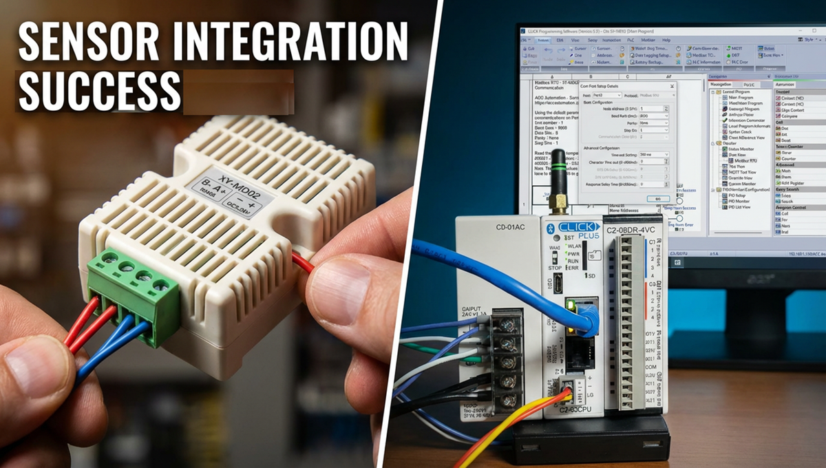
Using Modbus RTU (RS485), we will connect the XY-MD02 Temperature and Humidity Sensor to the Click PLC. The Click will be the Client (Master), and the Sensor will be the Server (Slave). This is an ideal sensor to place in a panel to ensure that the panel is within a working temperature and humidity range.
The XY-MD02 is an industrial Modbus RTU device that reads temperature and humidity. We will create a Click PLC program that will read the temperature and humidity from the sensor. We will also read the parameters from this sensor, like unit number, baud rate, temperature offset, and humidity offset. Let’s get started.
Our entire Click series can be found here. All of the previous information for the Click PLC can be applied to the Click PLUS.
Previously, here is some of the thing we covered:
Software Installation – Video
Click Software Establish Communication – Video
MQTT Communication – Video
Data Logging – Video
Real-Time Clock with Network Time Service – Video
The programming software and manuals can be downloaded from the Automation Direct website free of charge.
Watch the video below to see the Click PLC communicate to the XY-MD02 temp and humidity sensor.
The XY-MD02 can be purchased from the following Amazon affiliate links.
Amazon.com
Amazon.ca
Here are some features of this high-precision SHT20 temperature and humidity sensor:
1 – Supports MODBUS RTU protocol
2 – RS485 supports 1000 meters of communication
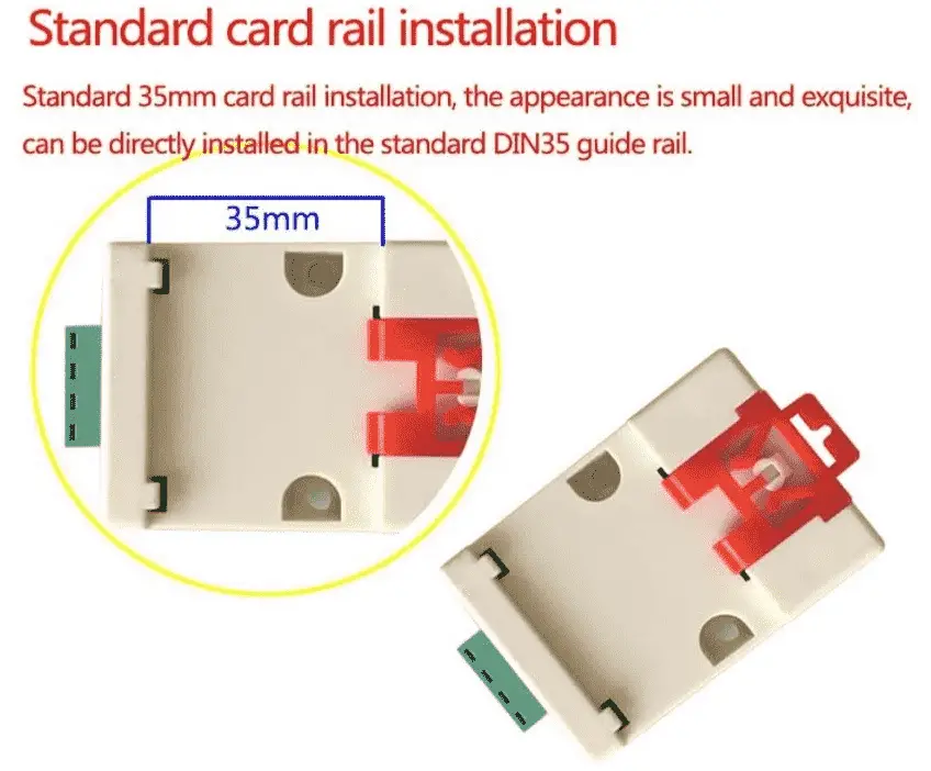
3 – Standard DIN35 mounting rails
4 – High precision
5 – Industrial products, high progress SHT20 temperature and humidity sensor, the RS485 communication
6 – Standard MODBUS protocol and ordinary protocol, the user can choose communication protocol
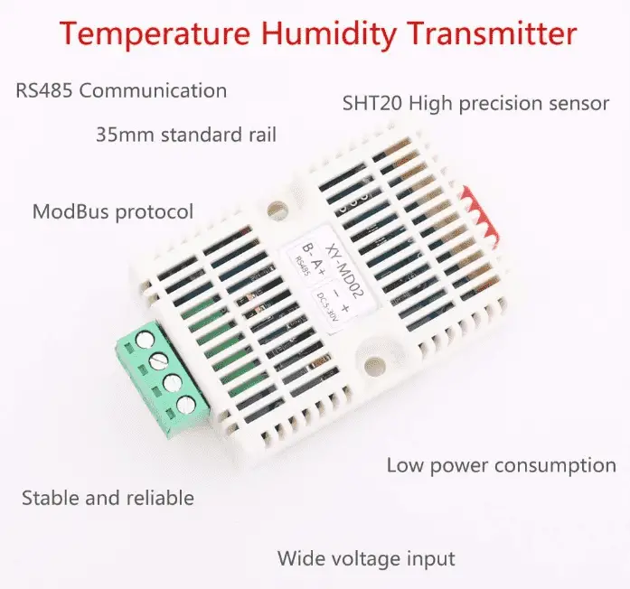
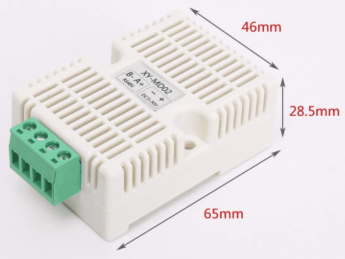
XY-MD02 Sensor Specifications
Product Name: Modbus RTU RS485 SHT20 Temperature Humidity Transmitter
– Product Number: XY-MD02
– Working Voltage: DC 5V~30V
– Output signal: RS485 signal
– Communication protocol: Modbus RTU and ordinary protocol
(Default parameters 9600, N, 8, 1)
– Communication address:1 to 247(default 1)
– Temperature Range: -40 to 60 ℃ +/-0.5℃
– Temperature Resolution: 0.1℃
– Humidity Range: 0% to 80%RH +/-3%RH
– Humidity Resolution: 0.1%RH
– Power: <0.2W
– Working Temperature:-40 to 85 ℃
– Working Humidity:0%~95%RH
– Size:65*46*28.5mm
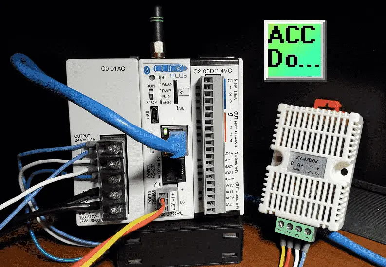
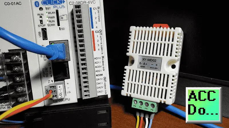
Wiring the XY-MD02 to a Click PLC
This temperature and humidity sensor is powered up by a DC supply. The voltage can be anywhere from 5 to 30 volts DC. In our case, we are using the 24 Volt DC supply for the Click PLC.
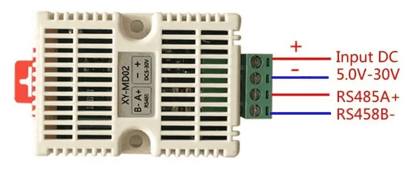
The Modbus RTU communication is a two-wire (Twisted Pair) connection.
RS485 A+ will be connected to the Click Port 3 +. RS485 B- will be connected to the click Port 3 -.
As you can see, the wiring of the sensor is straightforward. We would have to wire the units in parallel to expand this network to several other sensors. Each sensor would have a different unit number assigned so the program client can address the unit.
Click PLC Modbus RTU Program
To communicate to the XY-MD02 temp and humidity sensor, we need to set up the RS485 port on our Click PLUS PLC.
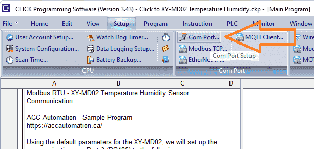
On the main menu, select Setup | Com Port…
The COM Port Setup window will now be displayed.
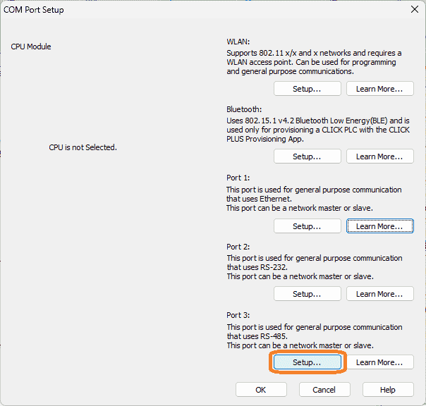
Port 3 is the RS485 type that we will use as the network master. (Client)
Select the Setup… button.
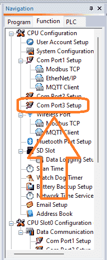
If you want to go directly to the Com Port Setup details window, select Com Port 3 Setup under the CPU Configuration on the Function Tab of the navigation window.
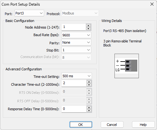
The Com Port Setup Details window will now be displayed. The port showing is three, and the protocol is set for Modbus. To the right-hand side, you will see the wiring details and a picture of the port. The basic configuration will set the communication that this network will use. Since this is the master (client), we will leave the default as node address 1. The baud rate will be 9600, parity none, one stop bit, and 8 data bits. This is the default for the XY-MD02 temperature and humidity sensor. We will leave the advanced configuration as their default. Our RS485 port is now set for the sensor.
We will be using two Receive Click PLC instructions. One is to get the current temperature and humidity, and the other is to get the parameters from the sensor.
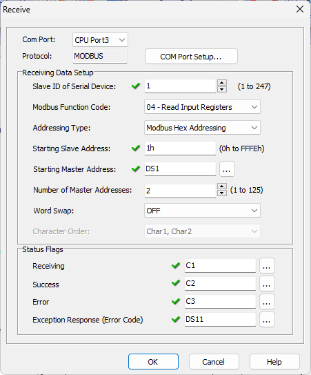
Here is our first Modbus instruction that will receive data for the temperature and humidity. The slave (server) of the sensor is 1. This is the default for the XY-MD02. Function code “04 – Read Input Registers” is used at Modbus Hex Address 1. We will read two registers and place them in the Click PLC memory starting at DS1. The status flags are set for us to use in the ladder logic to control the communication timing and see any error codes encountered.
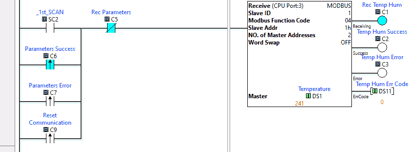
Here is the completed rung 1 of the Click ladder logic code. The first scan is used to start the communication to the XY-MD02 sensor.
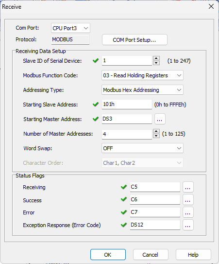
The second Modbus instruction will receive data for the sensor parameters. Again, slave (server) unit 1 is used. We will use the “03 – Read Holding Registers” function code at Modbus hexadecimal address 101 this time. We will read four addresses and place them in the Click PLC memory starting at DS3. Status flags are then set up to use in our ladder logic.
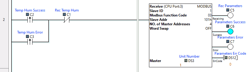
Here is rung 2 of the Click ladder logic code. The parameters are read when the temperature and humidity read is a success or failure, and the receiving bit is not on. Notice that the receiving, success, and error bits for the parameter reading are used in rung 1 for the first read.
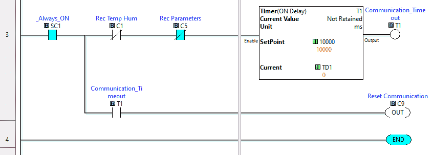
The third ladder logic rung will set a timer if the received bits for the Modbus reads are not activated within 10 seconds. Communications will reset when the timer times out.
This is the end of the Click PLC ladder logic program. Download this to the controller and ensure the PLC is running.
Watch the video below to see this program in action.
Monitoring the Click Ladder Logic Program
Using data view in the Click PLC programming software, we can watch the temperature, humidity, and parameters as the program runs.
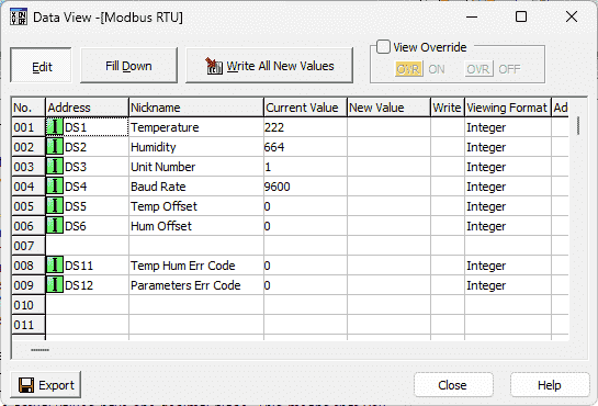
Note: The temperature and humidity have one decimal place. This is understood, but if you need to display this on an HMI, divide the number by ten and convert it to a real number in the PLC.
DS1 – Temperature – XX.X ℃
DS2 – Humidity – XX.X %RH
DS3 – Unit Address – Default 1
DS4 – Baud Rate – Default 9600
DS5 – Temperature offset for calibration
DS6 – Humidity offset for calibration
Download the sample Click Plus program here.
Watch the video below to see our Click Plus controller communicating Modbus RTU to the XY-MD02 temp humidity sensor.
XY-MD02 Temperature Humidity Sensor – Modbus RTU (RS485)
Purchase
Amazon.com
Amazon.ca
Manual
Specifications and Documentation
Connection to Raspberry Pi
Click PLC Support Links
The Click PLC can be programmed using free Click programming software from Automation Direct. Here is a link to the software.
Version 3.00
Version 2.60
The entire Click PLC series before the Click PLUS release can be found here.
All previous posts and information are still valid with the Click PLC line-up.
YouTube Click Playlist
YouTube Click PLUS Playlist
Click and Click PLUS PLC Overview
Click and Click PLUS PLC Videos from Automation Direct
Watch on YouTube: Integrating an XY-MD02 Sensor with Modbus RTU into Click PLC
If you have any questions or need further information, please contact me.
Thank you,
Garry
If you’re like most of my readers, you’re committed to learning about technology. Numbering systems used in PLCs are not difficult to learn and understand. We will walk through the numbering systems used in PLCs. This includes Bits, Decimal, Hexadecimal, ASCII, and Floating Point.
To get this free article, subscribe to my free email newsletter.
Use the information to inform other people how numbering systems work. Sign up now.

The ‘Robust Data Logging for Free’ eBook is also available as a free download. The link is included when you subscribe to ACC Automation.