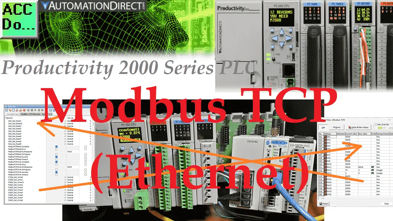
The Productivity 2000 series of PLCs has five built-in communication ports for easy connectivity to your PC or various industrial networks. Ethernet protocols like Modbus TCP can be utilized with the RJ45 port on this PLC. Modbus TCP is an open (published) protocol that uses the Server (Master) / Client (Slave) architecture. It’s a very common protocol used in industrial automation controls.
We will use the RJ45 (Ethernet) port to communicate to a Click PLC. Modbus TCP will be the protocol used on this Ethernet communication media. The Productivity 2000 PLC will be the server, and the Click PLC will be the client. We will be creating a network between the two PLC units. A heartbeat will be used, so if communications are lost, the server (slave) will know. The throughput time will be timed using a small Click PLC program. You will soon see how the Productivity Series of PLCs best handles communication with other devices. Let’s get started.
Previously in this Productivity 2000 series PLC, we have discussed the following:
P2000 Hardware Features – Video
Productivity Suite Software Install – Video
Communication (System Configuration) – Video
First Program – Video
Debug Mode – Video
PLC Program Documentation – Video
PLC CPU Display – Video
PLC Online Programming – Video
PLC Tag Database – Video
Ladder Logic Contacts – Video
Ladder Logic Outputs – Video
Timers – Video
Counter – Video
Productivity 2000 PLC Ladder Logic Math – Video
Data Handling Instructions
Part 1 – Video
Part 2 – Video
Array Functions
Part 1 – Video
Part 2 – Video
Part 3 – Video
P2000 Program Control – Video
Drum Sequencer Instructions – Video
Data Logger and Logging – Video
Web Server (HTTP) – Video
Modbus RTU Serial Communication – Video
Watch the video below to see the running and configuration of the Modbus TCP Ethernet Communication from the Productivity 2000 Series PLC to the Click PLC.
Productivity to Click PLC – System Configuration
We will write and read ten 16-bit registers each to and from the Click PLC from our Productivity 2000 PLC.
Click PLC Productivity 2000 PLC
DH1 ——————– P2000_Net_Write1 – Bit 1 = Heartbeat Bit (1sec on 1sec off)
DH2 ——————– P2000_Net_Write2
DH3 ——————– P2000_Net_Write3
DH4 ——————– P2000_Net_Write4
DH5 ——————– P2000_Net_Write5
DH6 ——————– P2000_Net_Write6
DH7 ——————– P2000_Net_Write7
DH8 ——————– P2000_Net_Write8
DH9 ——————– P2000_Net_Write9
DH10——————- P2000_Net_Write10
DH11——————- P2000_Net_Read1
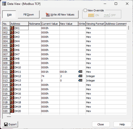
DH12——————- P2000_Net_Read2 = Throughput Time Captured
DH13——————- P2000_Net_Read3
DH14——————- P2000_Net_Read4
DH15——————- P2000_Net_Read5
DH16——————- P2000_Net_Read6
DH17——————- P2000_Net_Read7
DH18——————- P2000_Net_Read8
DH19——————- P2000_Net_Read9
DH20——————- P2000_Net_Read10
Note: If we wish to extend our network with a third PLC that would share information with the network, we will do the following. Read ten registers and write 20 registers from and to the 3rd PLC. We would then write 20 registers to the Click PLC. This includes the existing 10, plus the ten read registers from the 3rd PLC.
Click PLC Configuration – Modbus TCP Server
The first thing that we will do is set up the Click PLC Ethernet port.
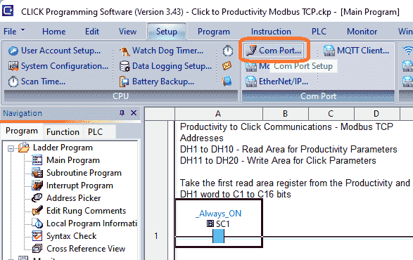
You can access the Com Port Setup by using the main menu | Setup | Com Port Setup…
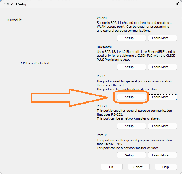
Select Port 1: Setup for the Ethernet.
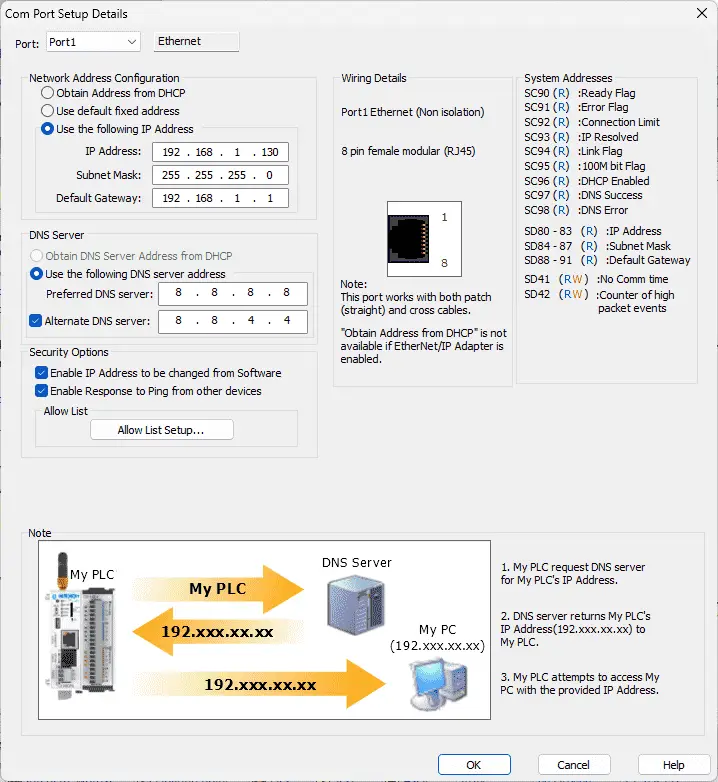
You will notice that the Modbus protocol is already selected. We will use the manual settings for the Network Address Configuration.
IP Address: 192.168.1.130
Subnet Mask: 255.255.255.0
The default gateway will be 192.168.1.1, exposing it to the internet.
Since the Click PLC will be configured as a Server (Slave), ensure that the TCP Port Number is set to 502. This is the default port for Modbus TCP Protocol. We will leave everything else as a default. Select OK to close the Com Port Setup Details. Select OK again to close the COM Port Setup.
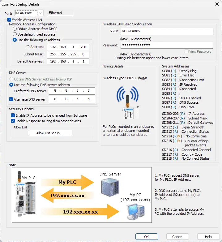
The Wi-Fi port WLAN can be set up similarly by selecting it from the drop-down menu for the port.
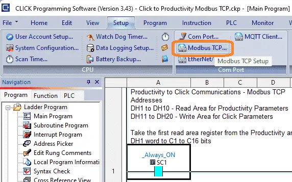
Modbus TCP Server is turned on by default, but you can select this from the main menu | Setup | Modbus TCP…
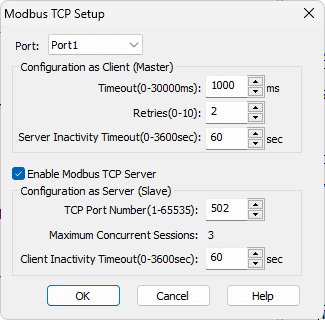
You can verify that the “Enable Modbus TCP Server” is selected for Port 1.
We will now find the Modbus addresses in the Click programming software from the Address Picker.
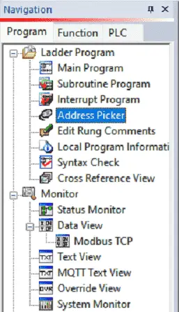
Select Address Picker under the Ladder Program in the Navigation menu. You can access this via the main menu | Program | Address Picker… or CTRL + T.
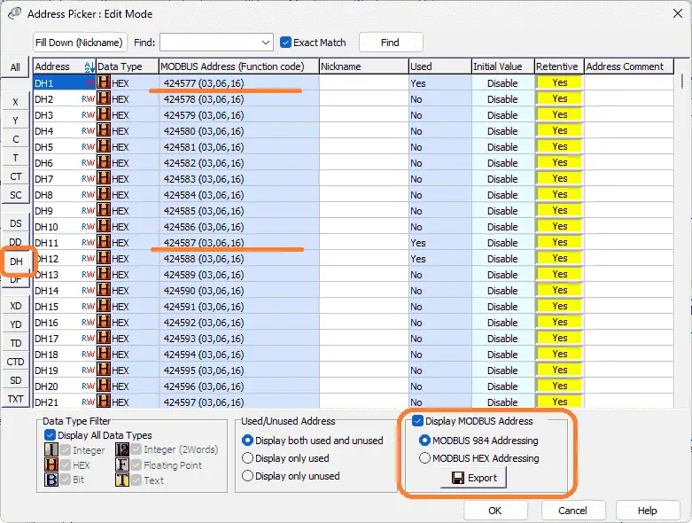
Select the DH area on the left side of the address picker edit mode. Ensure that Display Modbus Address is selected. We are using MODBUS 984 Addressing. Note the following:
DH1 – Modbus Address 424577
DH11 – Modbus Address 424587
Select OK to close the address picker window.
More information can be obtained by going to our Click PLC Series page. This will go through most of the features of this cost-effective programmable logic controller.
Productivity 2000 Modbus Overview
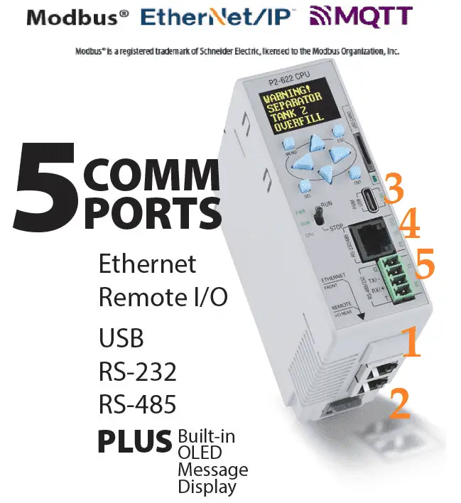
1 – 10/100 MB Ethernet Port
2 – Remote I/O
3 – Micro USB 2.0 Programming Port
4- RS232 Serial Port (RJ12)
5 – RS485 Serial Port (TB Style)
Modbus TCP protocol through the Ethernet port (RJ45) is the method in which we will communicate to the Click PLC. This is a client (master) / server (slave) protocol. The client sends a request, and the server will respond to that request only. The Modbus TCP protocol can be reviewed at the following URLs.
https://www.rtautomation.com/technologies/modbus-tcpip/
http://www.simplymodbus.ca/TCP.htm
Productivity 2000 Port Setup – Modbus TCP Client
The Ethernet RJ45 port must be set up. Under the Setup in the Application Tools, select Hardware Config.
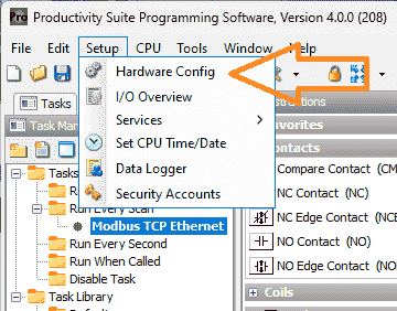
Alternatively, you can use the main menu | Setup | Hardware Config.
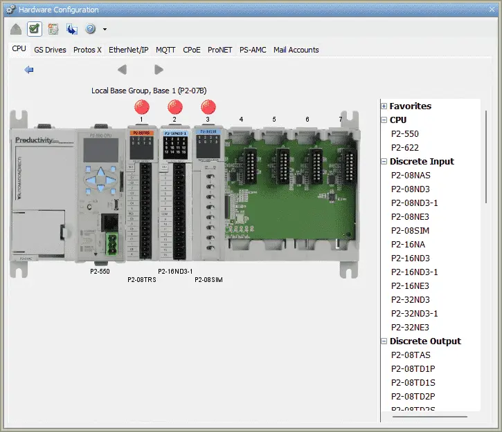
The hardware configuration window will now be displayed—Double-click on the CPU unit.
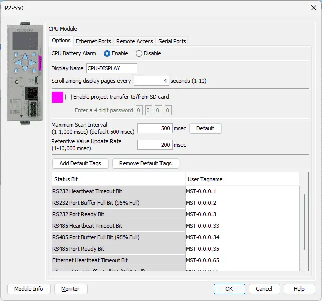
This will bring up the P2-550 CPU model window. Select the Ethernet Port tab at the top of the screen.
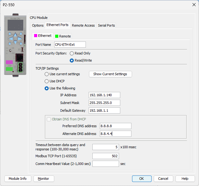
Our port settings are set to the following.
IP Address: 192.168.1.140
Subnet Mask: 255.255.255.0
These settings indicate that the Click PLC can communicate to the Productivity 2000 PLC. (What Everybody Ought to Know about IP Addressing)
The default gateway is 192.168.1.1, so it can connect to the internet.
Select OK after setting these parameters.
Click the x on the hardware configuration window. We are now finished setting the Ethernet port of the PLC for communication.
Productivity 2000 PLC Program
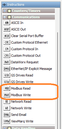
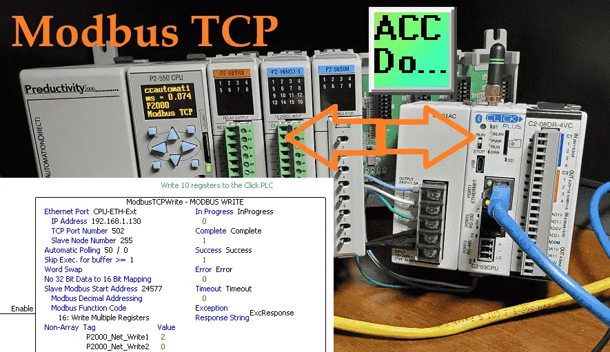
We will use the Modbus Read (MRX) and the Modbus Write (MWX) instructions for our Modbus TCP master program.
Modbus Write (MWX)
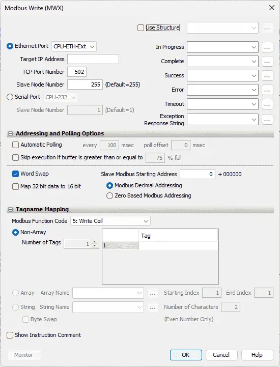
This instruction is broken down into three sections. The first is the instruction parameters.
Select the Ethernet Port – CPU-ETH-Ext
IP Address is set for 192.168.1.130 – Click PLC
The slave node number is set to the default of 255. Since Modbus TCP uses the IP address, this is not utilized for our instruction.
We will use the structure with the name of ModbusTCPWrite. This will set up the corresponding addresses and bits for this instruction.
The second part is addressing and polling options. This makes the setting of the Modbus Master the easiest that I have seen. The Automatic Polling feature allows you to choose the rate at your desire to send messages without having to use a separate timer and enable logic. The Message Queue stages the messages from the ladder code to go out to each physical communications port without requiring interlocking logic. The longer the poll time within the application’s tolerance, the better the overall network performance. So for efficiency in programming and the best possible performance for the system, conservative poll rates should be used when utilizing the Automatic Poll feature. There is also a Poll offset field in the communications instructions. This helps prevent the instructions from being queued all at the same time. When the CPU project starts, there is a master timer that begins. The ladder scan will look to see if the instruction is enabled. If it is enabled, it will begin the Automatic Poll timer at the specified poll offset value from the master time clock.
We will select automatic polling at 50 milliseconds. This means that all of the timing between all of the Modbus Write and Read commands will be automatically handled by the PLC firmware.
Our Slave Modbus Starting Address is 24577. Note that the +400000 is added based on the Modbus Function Code selected. This is the Modbus address for DH1.
We will be using Modbus Decimal Addressing.
The third part of the instruction is Tagname Mapping. This will specify where the information is located to be written to the Click PLC. We will create a Non-Array of 10 tags. Our Tags will be a 16-bit integer named P2000_Net_Write1 to P2000_Net_Write10.
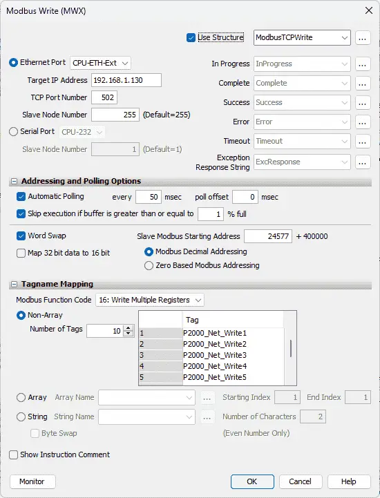
Here is our completed Modbus Write instruction.
Modbus Read (MRX)
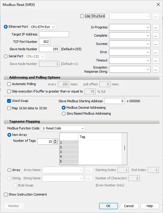
This instruction is broken down into three sections. The first is the instruction parameters.
Select the Ethernet Port – CPU-ETH-Ext
IP Address is set for 192.168.1.130 – Click PLC
The slave node number is set to the default of 255. Since Modbus TCP uses the IP address, this is not utilized for our instruction.
We will use the structure with the name of ModbusTCPRead. This will set up the corresponding addresses and bits for this instruction.
The second part is the addressing and polling options. Automatic Polling performs all of the sequencing, so you do not have to write any logic.
We will select automatic polling at 50 milliseconds. Our poll offset will be set at 25 milliseconds. This means that when this instruction executes, a delay of 25 milliseconds will be observed before the first read takes place.
Our Slave Modbus Starting Address is 24587. Note that the +400000 is added based on the Modbus Function Code selected. This is the Modbus address of DH11 of our Click PLC.
We will be using Modbus Decimal Addressing.
The third part of the instruction is Tagname Mapping. This will specify where the information read is to be placed. We will create a Non-Array of 10 tags. Our Tags will be 16-bit integers named Click_Net_Read1 to Click_Net_Read10. This will read the values of these registers from our Click and place them into our Productivity PLC.
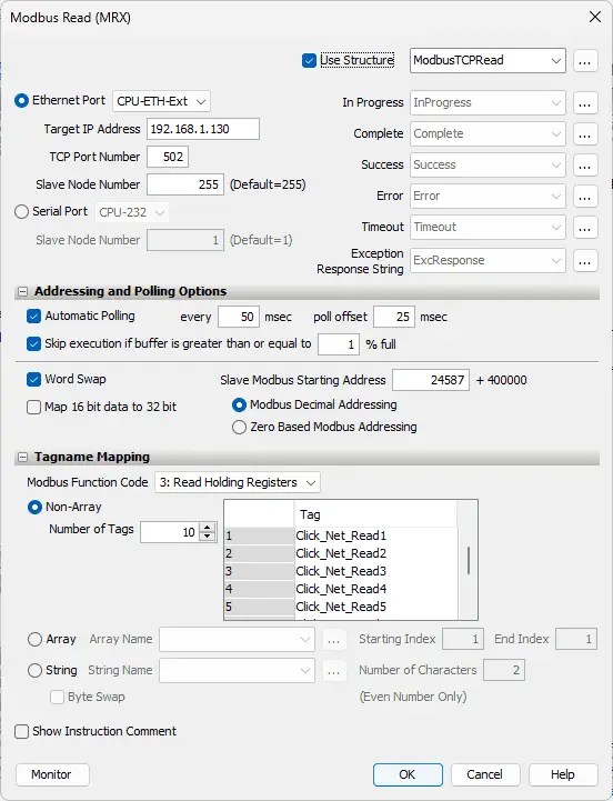
Here is our completed Modbus Read instruction.
Here is our program for the Modbus Write and Read instruction.
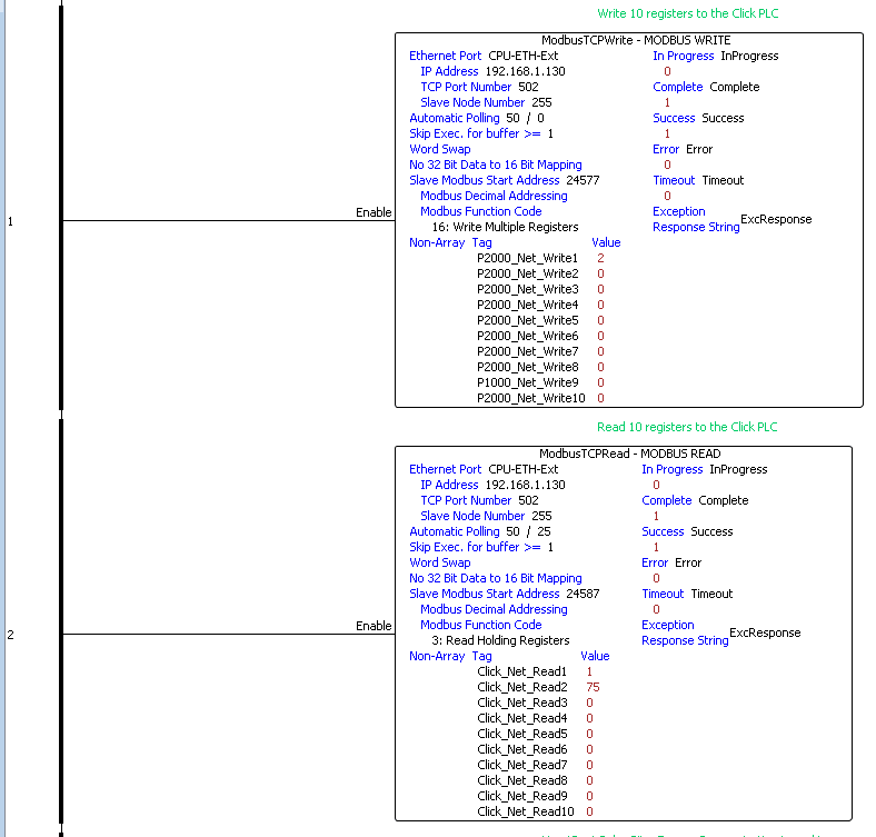
Note that the Modbus read and write instructions do not have any logic to enable them. They are always enabled because the automatic polling will take care of the timing sequence for us.
HeartBeat Pulse Bit – Ensure Communication is working
The Productivity will send out a pulse bit that can be used to determine if communications are good. This pulse bit will be on and off for one second.
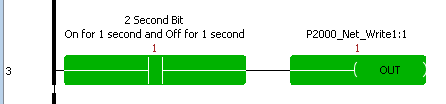
The heartbeat pulse bit will osculate bit 1 of P2000_Net_Write1 on and off. Our Click PLC can then use this to determine if communication is functioning correctly.
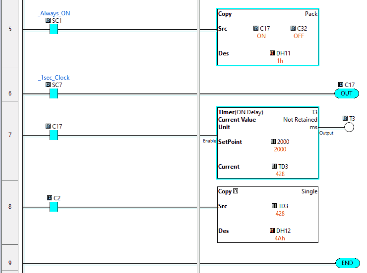
Here is the program in the Click PLC for the Heartbeat.
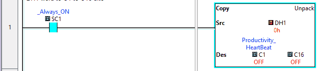
Take the first read area register from the Productivity and separate it into individual bits.
DH1 word to C1 to C16 bits
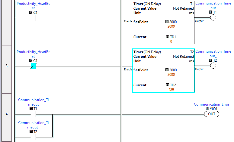
The Productivity will pulse a bit on and off for a second. This will set up the heartbeat to detect communication loss. When the heartbeat bit is on or off, delay timers are started. The timers have a set value of 2 seconds. If either timer is activated, then output Y1 will come on. This will indicate that we have a communication error.
Determine the Throughput Time of the Network
The Click PLC is setting a bit on, and we are, in turn, turning a bit on in the Productivity PLC.
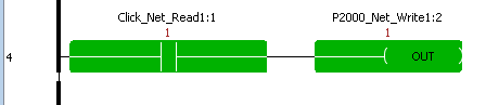
The Click program will use a timer to determine the time it takes for the signal to be sent and returned on the network. The result in milliseconds is located in P2000_Net_Read2 register.
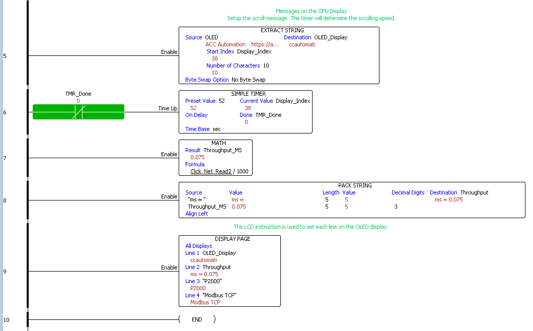
The P2000 ladder logic code will show the system’s throughput on the LED display.
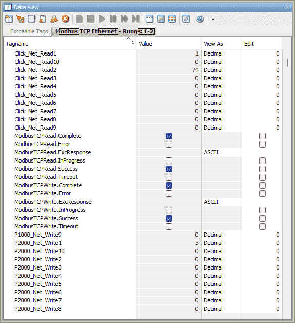
Monitoring the network can be done using the Data View windows on both the Productivity Suite and Click PLC Programming software packages.
Download the PLC programs here.
Watch the video below to see the running and configuration of the Modbus TCP Ethernet Communication from the Productivity 2000 Series PLC to the Click PLC.
Productivity 2000 Series PLC from Automation Direct
Overview Link (Additional Information on the Unit)
Configuration (Configure and purchase a system – BOM)
User Manual and Inserts (Installation and Setup Guides)
Productivity Suite Overview (Features of the fully functional free software package for the Productivity Family of PLC (PAC) controllers)
Productivity Suite Programming Software (Free Download Link)
This software contains all the instructions and help files for the Productivity Series.
Watch on YouTube: Productivity 2000 Series PLC Modbus TCP Ethernet
If you have any questions or need further information, please contact me.
Thank you,
Garry
If you’re like most of my readers, you’re committed to learning about technology. Numbering systems used in PLCs are not challenging to learn and understand. We will walk through the numbering systems used in PLCs. This includes Bits, decimals, Hexadecimal, ASCII, and Floating points.
To get this free article, subscribe to my free email newsletter.
Use the information to inform other people how numbering systems work. Sign up now.

The ‘Robust Data Logging for Free’ eBook is also available for free download. The link is included when you subscribe to ACC Automation.