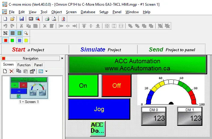
The C-More Micro HMI panel is a series of human-machine interfaces (HMI) that provide a way for the operator to control and view your programmable logic controller. (PLC) The free C-more microprogramming software is user friendly and fully featured. C-more Micro panels can easily display text, graphics, and bitmaps to effectively communicate critical data to your operator.
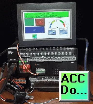
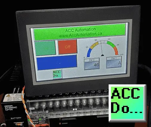
We will connect the EA3-T4CL cmore micro HMI screen to the Omron CP1H PLC. The devices will communicate serially via an RS485 interface. We will demonstrate reading and writing bits and words from the HMI unit. Let’s get started.
Previously in this C-More Micro HMI Panel series, we have done the following:
System Hardware – Video
Installing the Software – Video
– Update Automation Direct Software C-More Micro HMI Video
System Setup Screens – Video
First Program – Video
First Program Part 2 (PLC < – > Panel) – Video
Common Screen Menu – Video
Simulate Project – Video
Object List Shapes – Video
Object Buttons and Indicators – Video
Object Numeric Entry – Video
Object Meters and Graphs – Video
Object Bitmap – Video
Object Recipe – Video
Object Text – Video
Device Driver for Omron PLC CP1H
The CP1H PLC can communicate Host Link (C Mode Commands) Serial – RS232, RS485, RS422. It can also communicate Ethernet FINS via a communications module.
Communications drivers currently included in the C-More Micro HMI for the Omron controllers are as follows.
• Omron C200 / C500 Host Link Adapter
• Omron CS / CJ FINS Serial
These will handle any serial communication of the Omron Series of programmable logic controllers.
Watch the video below to see our C-More Micro HMI Panel communicate to the Omron PLC.
Device Drivers for C-More Micro HMI
The following protocols are supported, and all the drivers are included with C-more Micro:
– AutomationDirect Productivity series
– AutomationDirect Do-more
– AutomationDirect CLICK (Modbus)
– DirectLOGIC K-sequence, DirectLOGIC DirectNET,
– DirectLOGIC Modbus (Koyo Addressing)
– Modbus RTU
– Allen Bradley DF1 Full Duplex,
– Allen Bradley DF1 Half Duplex,
– Allen Bradley PLC5 DF1,
– AB DH485
– Omron Host Link (C200 Adapter, C500)
– Omron FINS serial (CJ1, CS1)
– GE SNPX (90/30, 90/70, Micro 90, VersaMax Micro)
– Mitsubishi Melsec FX
– Siemens PPI
– Entivity Modbus RTU
– AutomationDirect GS Drives
– AutomationDirect SOLO Temperature Controllers
– Mitsubishi Q/QnA
Hardware
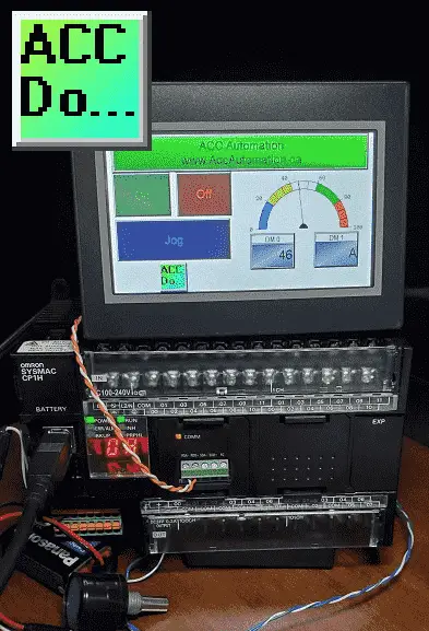
We will be connecting the C-More Micro HMI model EA3-T4CL to the Omron CP1H-XA40DR-A PLC. The Omron also has a communication plugin module part number CP1W-CIF12-V1. This is an RS485 communication module that will use Omron host link serial commands.
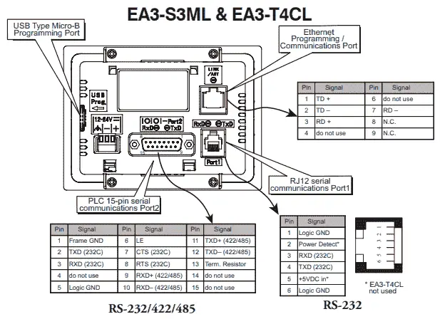
Communication Wiring
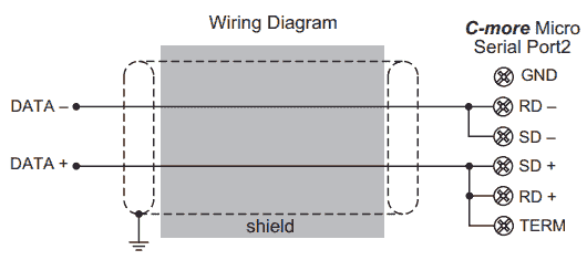
RS485 is a two-wire system. Port 2 of the Micro HMI will communicate to the plugin Omron communication module. RD- and SD- are jumped together. SD+ and RD+ are also jumped together on the cmore micro port 2.
This is easily done using the terminal block connector.
The following DB15 connector for your C-More is an associate amazon link. This connector is ideal for connecting your C-more.
CP1H PLC Program
Here is a link to our entire Omron CP1H PLC series. This series will take you through all of the programming instructions and software (CX-Programmer) for the PLC.
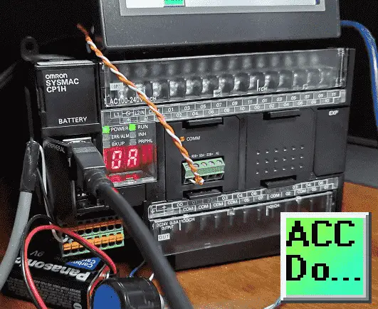
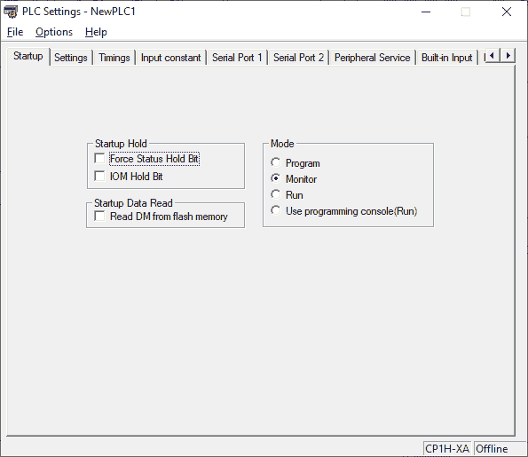
The Omron PLC defaults to Run mode. (Use programming console (Run)) This is the mode of the CP1H when it is powered. (Supply voltage applied) Communication with the CP1H will be done through the serial port. In order to change parameters in the PLC, this mode must be in Monitor for the Omron PLC.
Using CX-Programmer we can go to the PLC Settings and change the start-up to monitor mode.
(main menu | PLC | Edit | Settings…)
Start Stop Jog Circuit
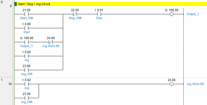
The following link will explain the code for the circuit.
How to make a start-stop jog circuit in a PLC.
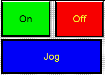
The C-More HMI Screen will use three momentary buttons and one pilot light.
The PLC Address will be set for the following:
Start – IR21/0
Stop – IR22/0
Jog – IR23/0
Output – IR100/00
Analog Input – Gauge display

Using the built-in analog on the CPU unit we attach our analog device and then use the scaling instruction. The scaling instruction will take our signal in and convert this to a number between 0 and 100. This will represent the percent on the gauge.
Create an analog voltage input tester for a PLC.
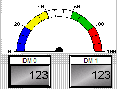
Here are the properties for the gauge display:
Analog Input – DM0 – BCD integer 16-bits
CPU LED Display – Digital Panel Meter

The Omron CP1H has a two-digit LED display that can be used to display information. We use the SCH(047) instruction to display either the upper or lower two digits. In our case, we will be displaying the lower two digits from data memory 1 (D1). The information will be coming from our HMI screen.
See the picture above.
DM1 – DM1 – Unsigned integer 16-bits
C-More Micro Programming Software
The entire C-More Micro HMI Series can be found at this link.
We will start a new project.
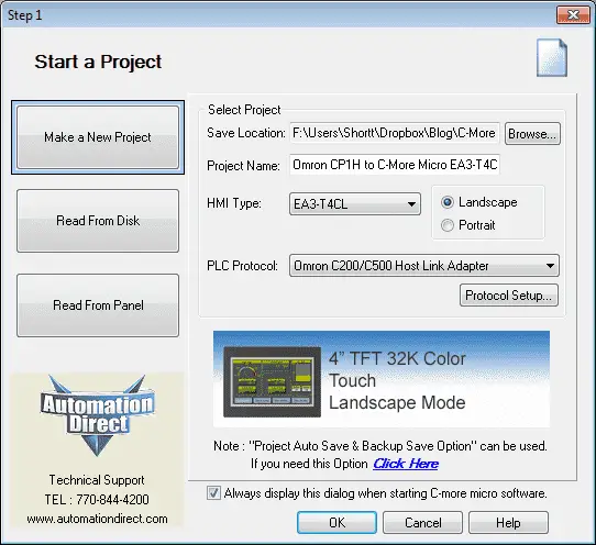
Our panel type will be the EA3-T4CL. This is a 4″ TFT 32K colour touch landscape human-machine interface. A picture of the unit is displayed to ensure that you have selected the correct model.
The PLC protocol will be set for the Omron C200/C500 host link adapter. This is a serial type of communication. Select the protocol setup… button.
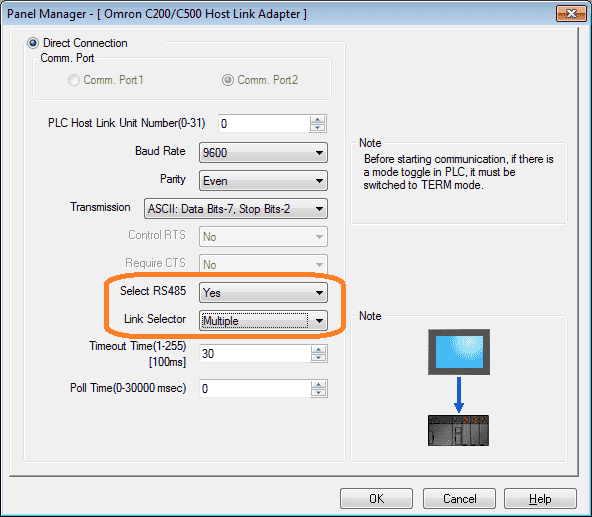
Port 2 on the unit is selected which is the RS485. The baud rate and other serial parameters must match the Omron unit. (9600, even, 7, 2 is usually the default for the Omron serial ports.)
Our PLC host link unit number will be left at the default of 0.
Select RS485 needs to be set for Yes and the link selector must be set to Multiple. This means that the communication is a one to many (1:N) type. Selecting single will change the protocol to 1:1 and our communication will not work.
Tag Name Database
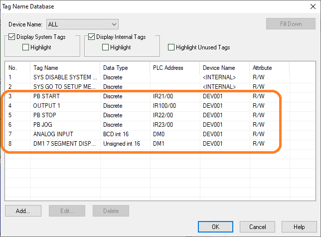
Our tag name database is as follows. This was discussed above.
Simulation
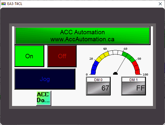
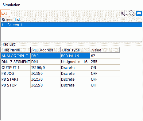
The built-in simulation can allow you to visually see how your screen will look and function before transferring to the physical unit.
Download the PLC and C-More Micro program here.
Watch the video below to see the Omron CP1H communicate RS485 to our C-More Micro HMI Panel. This will also demonstrate the PLC ladder code for functionality.
C-More Micro Panels from Automation Direct
https://www.automationdirect.com/adc/Shopping/Catalog/HMI_(Human_Machine_Interface)/C-more_Micro_Panels
C-More Micro – Graphic Panel (EA3 Series) User Manual and Quick Start Guides
https://cdn.automationdirect.com/static/manuals/ea3mguserm/ea3mguserm.html
EA3-T4CL C-More Micro Specifications
https://cdn.automationdirect.com/static/specs/ea3t4cl.pdf
C-More Micro Programming Software V4.30
http://support.automationdirect.com/products/cmoremicro.html
This free software will enable you to program all of the C-More Micro HMI units. It includes a simulator for your application.
Watch on YouTube: Omron CP1H to C-More Micro HMI Communication
If you have any questions or need further information please contact me.
Thank you,
Garry
If you’re like most of my readers, you’re committed to learning about technology. Numbering systems used in PLC’s are not difficult to learn and understand. We will walk through the numbering systems used in PLCs. This includes Bits, Decimal, Hexadecimal, ASCII and Floating Point.
To get this free article, subscribe to my free email newsletter.
Use the information to inform other people how numbering systems work. Sign up now.
The ‘Robust Data Logging for Free’ eBook is also available as a free download. The link is included when you subscribe to ACC Automation.

