Programmable logic controllers (PLC) use a cyclic scan. The time that it takes to complete one scan is called Scan Time. Typical scan times range from 10 milliseconds to 10 microseconds. This translates from 0.01 to 0.0001 seconds per PLC scan. Understanding how the program scan will help us in programming and troubleshooting the PLC.
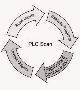
The simplest scan cycle of a PLC consists of 4 steps. Read inputs, execute program, diagnostics, and communication, and update outputs.
We will be looking at each of these steps in a little more detail as we discuss the PLC program cyclic scan. Let’s get started.
Previously in this PLC Learning Series:
PLC Training Series – Tutorial for Everyone – Video
What are PLC Inputs? – Video
What are PLC Outputs? – Video
Memory Backup – Video
Understanding Numbers – Video
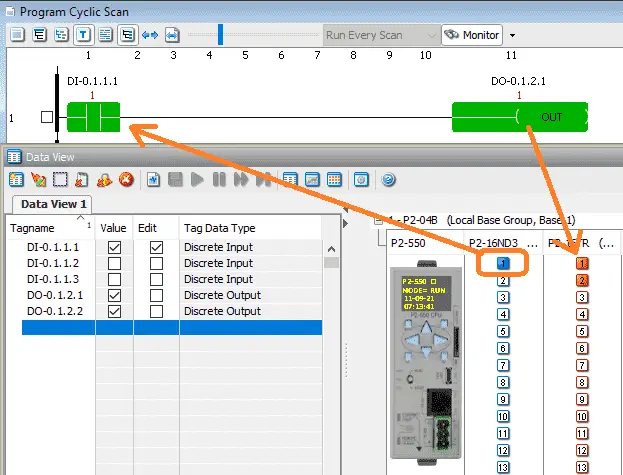
PLC Scan – Read Inputs
All of the physical PLC inputs are read at least once during each scan. The status of these inputs can then be used in the ladder logic program code. Depending on the controller used, and immediately updated input can be used if the condition of the input changes within the program scan.
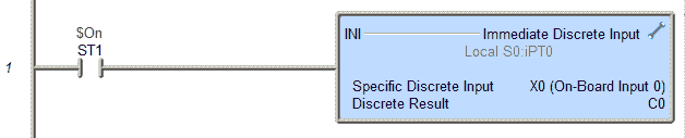 Here is an example using the BRX PLC with Do-More Designer Software.
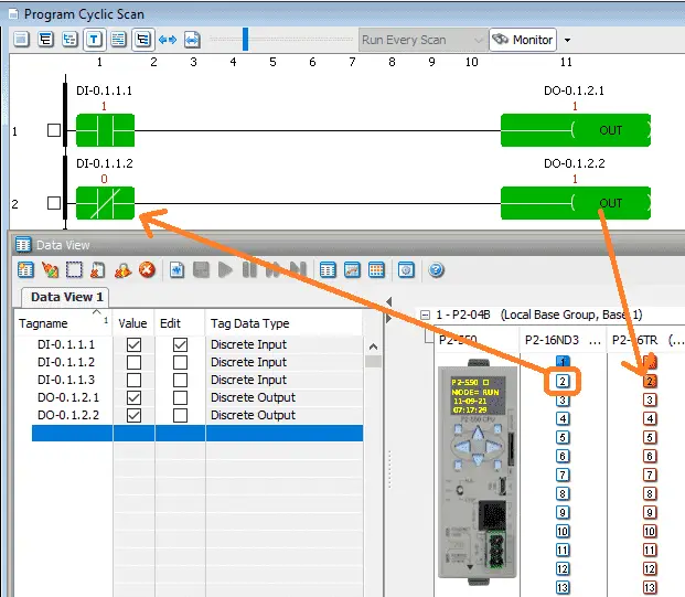
Once we know the status of the inputs, we can now execute our program.
PLC Scan – Program Execution
The PLC program consists of a set of instructions that are to be implemented for an industrial real-time application. Outputs are controlled based on the input conditions.
 Ladder logic is the most common method for programming a PLC. This graphical language comprises a series of rungs. They form to look like a ladder. Inputs are on the left side of the rung and outputs are on the right side. If the input condition(s) are true then the outputs of the rung are true. If the input logic is false then the outputs will be false. Logic conditions can be stated in a number of different terms.
TRUE / FALSE
1 / 0
ON / OFF
All of these terms are interchangeable when referring to the logic on PLC rungs.
Watch the video below to see the status of inputs and outputs using the Productivity Suite PLC simulator.
The symbols used on the ladder rungs are contacts and coils. They are closely related to the electrical schematics that are used by electricians, technicians, and others with electrical backgrounds. This makes it easier for many people to read and understand the logic when troubleshooting or developing the logic.
NO Contact (Normally Open)
 A NO contact on the rung means to take the input logic. If this were a physical input, look at the input light. If it is on then the NO contact will be on. If it is off, then the NO contact will be off.
NC Contact (Normally Close)
 An NC contact on the rung means taking the opposite of the input logic. If a physical input light is off, then the NC contact on the rung will be on. If the physical input is on, then the NC contact logic on the rung is off.
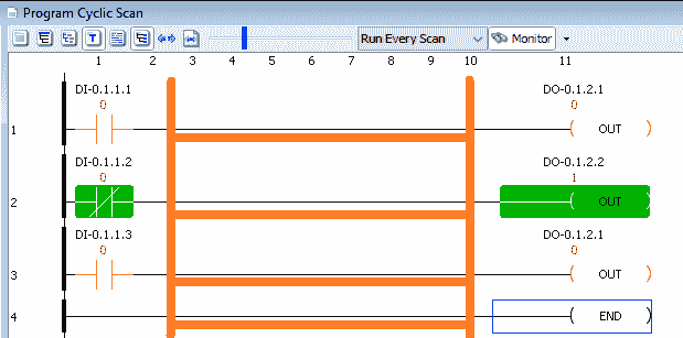
Normally a PLC will solve your logic from left to right, top to bottom. The status of the memory from the previous rung is available for the next rung to use.
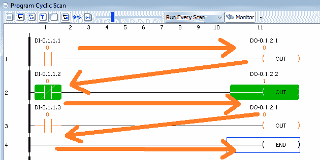 Outputs are normally used only once in ladder logic.
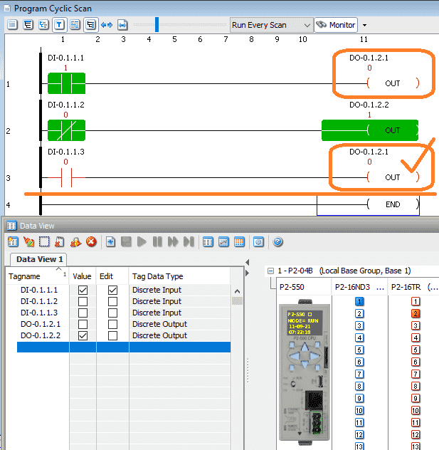 In the above example, we have used output DO-0.1.2.1 on rung 1 and rung 3. The logic in the PLC is solved from left to right, top to bottom. Since rung 1 logic is true, the output is turned on. Rung 2 is then solved. On rung 3 the input condition is false so the output is false. This is the value that is used as the output for the physical output point. The last output condition is what is used to update the physical outputs.
Watch the video below to see this in action using the Productivity Suite PLC simulator.
When troubleshooting PLC logic, sometimes moving a rung to the end of the program will make it function. You can then look for duplicate outputs in your ladder logic code.
PLC Scan – Diagnostics and Communication
The PLC is an industrial computer. Computers are prone to failure so this must be prevented. Diagnostics ensure that the memory and hardware are correct and functioning correctly for every scan of the controller. If not then warnings or errors are then activated. Refer to your PLC unit for the exact notifications that are given.
Programming or monitoring your PLC is done usually through communications. Communication can also mean with remote or local IO, network, etc. The scan will include a portion to handle all of these transactions.
PLC Scan – Update Outputs
All of the physical PLC outputs are written at least once during each scan. The outputs are determined by the ladder logic program code. Depending on the controller used, an immediate output can be used to change the physical output within the program scan.
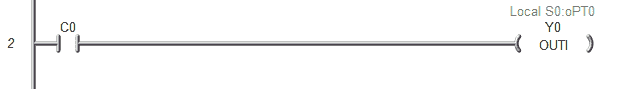 Here is an example using the BRX PLC with Do-More Designer Software.
Notes:
Older Modicon PLC like the 984 will scan the program logic from top to bottom, left to right. This would change the way you would logically troubleshoot this controller logic.
The above works with synchronous PLC scans. Controllers like Allen Bradley CompactLogix using the RSLogix 5000 software use asynchronous I/O scan. This means that the updating of I/O will happen whenever it can. In an asynchronous I/O scan, you typically will only use the actual I/O reference once in your program. Most programmers of these systems will transfer the I/O to internal memory first. They will then use the internal memory in the program code. This will now act as a synchronous predictable scan above.
PLC Beginner’s Guide to PLC Programming
There are many different PLC manufacturers with different hardware and software. All of the programmable logic controllers have similar basic features. Here is how I would approach learning about basic PLCs.
Once you are familiar with the basics of the PLC, you will then learn specifics for the controller you will be programming.
This is the easiest way to learn about PLC programming.
Watch on YouTube: PLC Learning Series – Program Cyclic Scan
If you have any questions or need further information, please contact me.
Thank you,
Garry
If you’re like most of my readers, you’re committed to learning about technology. Numbering systems used in PLCs are not difficult to learn and understand. We will walk through the numbering systems used in PLCs. This includes Bits, Decimals, Hexadecimal, ASCII, and Floating Points.
To get this free article, subscribe to my free email newsletter.
Use the information to inform other people how numbering systems work. Sign up now.

The ‘Robust Data Logging for Free’ eBook is also available as a free download. The link is included when you subscribe to ACC Automation.