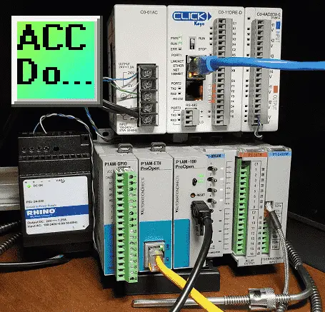
We will now connect our Productivity Open P1AM Arduino to a Click PLC. Using Modbus TCP the Arduino will be the Client (Master) and the Click will be the Server (Slave).
We will explain how to connect our P1AM-ETH Industrial Arduino Ethernet Shield to the Click PLC. The protocol will be Modbus TCP on an Ethernet communication network. Modbus is a master-slave type of communication. Masters will always send the commands to read or write to the slaves on the network. The slaves will respond if the communication is directed at them. Since this is an Ethernet network our master is known as a client and the slave as a server.
The P1AM Example from Automation Direct on GitHub will be used. It will be modified to write to holding registers and coils in the Click PLC.
github.com/AutomationDirect/P1AM-Examples/tree/master/P1AM-100_ModbusTCP_Client_Multiple
The temperature from the thermocouple input unit on the P1AM will be written to the Click PLC. Inputs from the simulator input card on our Arduino P1AM will be written to the Click PLC outputs directly. The Click PLC will also be programmed with a heartbeat circuit. This will detect if communications have been severed and will reset the outputs after 5 seconds. Let’s get started with our Arduino P1AM Modbus client to Click Modbus server.
Previous posts in this Productivity Open Arduino Compatible Industrial Controller Series
A full list can be obtained at the following location:
Productivity Open (P1AM-100) Arduino Controller
Productivity Open Arduino Controller Hardware
– Starter Kit Unboxing Video
– Powering Up Video
Installing the Software – Video
First Program – Video
Program Structure – Video
Variables Data Types – Video
Serial Monitor COM – Video
Program Control – Video
Operators – Video
GPIO Inputs and Outputs – Video
Math Instructions – Video
Time Instructions – Video
P1000 Expansion Analog Combination Module – Video
P1000 Expansion Digital Inputs and Outputs Part 1 – Video
P1000 Expansion Digital Inputs and Outputs Part 2 – Video
Watchdog Timer – Video
P1000 Expansion Thermocouple Module – Video
PID Control – Video
P1AM Arduino Modbus TCP to C-More Micro EA3 – Video
P1AM Arduino Modbus TCP to C-More EA9 – Video
Ethernet Shield Web Server – Video
Watch the video below to see a sample program (sketch) of the P1AM-ETH Modbus TCP Client communicating to our Click PLC Modbus TCP server.
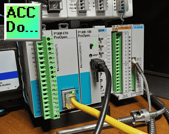
P1AM-ETH
Specifications
The P1AM-ETH is an industrially rated MKR format shield based on the WIZnet W5500 chip that adds Ethernet connectivity to the P1AM-100. The P1AM-ETH uses SPI to communicate with the P1AM-100 or other MKR format CPU. The P1AM-ETH uses the Arduino Ethernet library which comes standard with the Arduino IDE.
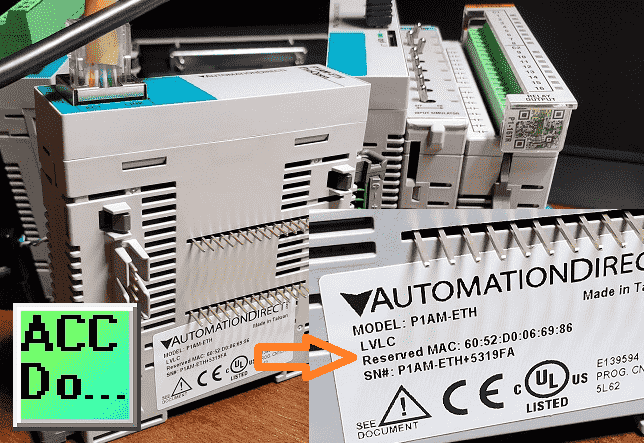
The MAC (Media Access Control) address is the physical hardware identification number. This is printed on the right-hand side label of our P1AM-ETH unit.
We will need this number for our program below.
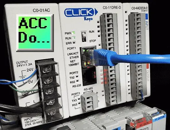
Click Modbus Server Configuration
Using the Click PLC programming software, we will set the Ethernet port IP address and ensure it is a Modbus Server.
Select main menu | Setup | Com Port Setup…
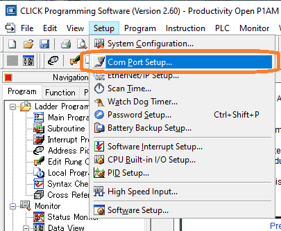
This will call up the COM Port Setup window. Port 1 is our Ethernet port. Select setup under port 1.
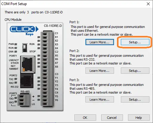
This will display the Com Port Setup Details window. A static IP address should always be used when setting up a network.
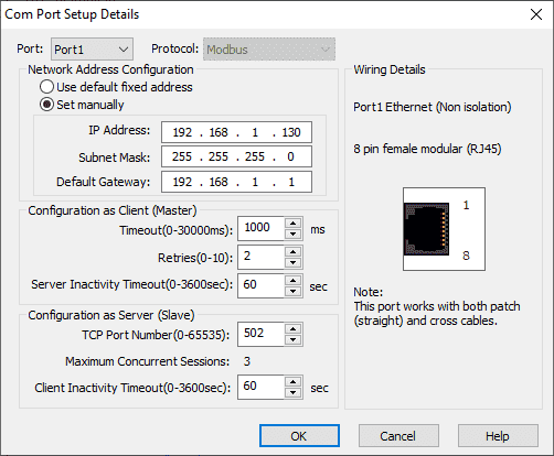
Select set manually under port 1 and type in the IP address, subnet mask, and default gateway.
Under configuration as a server (slave), we will leave the default assignments. 502 default TCP port number and 60 seconds for the client inactivity timeout. Select OK to save this configuration.
Click Modbus Addresses
The click programming software makes it easy to view Modbus addresses.
Select Address Picker under the ladder program in the program tab of the navigation menu. You can also use the main menu | Program | Address Picker.. or use Ctrl + T.
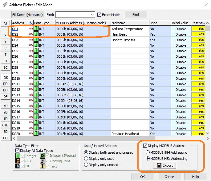
Select DS on the left-hand side of the address picker window. This will show you the DS area of memory available on the Click PLC. Select display Modbus addresses on the bottom right of the address picker window. Select Modbus HEX Addressing, because this is what will be used on the Arduino Modbus client program.
Click Address DS1 – Modbus 0000H – Arduino Temperature Input – XX.XX
Click Address DS2 – Modbus 0001H – Heartbeat – Incrementing number
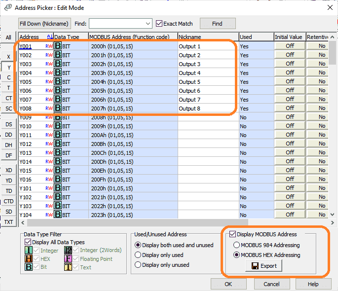
Select the Y (output) area of memory for the Click PLC. Here are the memory addresses we will be using for the Modbus communication.
Click Address Y001 – Modbus 2000H – Output bit – Discrete On/Off
Click Address Y002 – Modbus 2001H – Output bit – Discrete On/Off
Click Address Y003 – Modbus 2002H – Output bit – Discrete On/Off
Click Address Y004 – Modbus 2003H – Output bit – Discrete On/Off
Click Address Y005 – Modbus 2004H – Output bit – Discrete On/Off
Click Address Y006 – Modbus 2005H – Output bit – Discrete On/Off
Click Address Y007 – Modbus 2006H – Output bit – Discrete On/Off
Click Address Y008 – Modbus 2007H – Output bit – Discrete On/Off
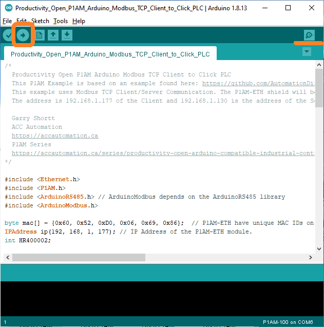
Arduino P1AM Modbus Client Program
We now have all of the information required to program our Arduino P1AM Modbus Client sketch.
Watch the video below for an explanation of the Arduino Modbus client code.
/*
Productivity Open P1AM Arduino Modbus TCP Client to Click PLC
This P1AM Example is based on an example found here: https://github.com/AutomationDirect/P1AM-Examples/blob/master/P1AM-100_ModbusTCP_Client_Multiple/P1AM-100_ModbusTCP_Client_Multiple.ino
This example uses Modbus TCP Client/Server Communication. The P1AM-ETH shield will be the client and sends the input values of a P1-08SIM and P1-04THM to a Click PLC.
The address is 192.168.1.177 of the Client and 192.168.1.130 is the address of the Server (Click PLC).
*/
#include
#include
#include // ArduinoModbus depends on the ArduinoRS485 library
#include
byte mac[] = {0x60, 0x52, 0xD0, 0x06, 0x69, 0x86}; // P1AM-ETH have unique MAC IDs on their product label
IPAddress ip(192, 168, 1, 177); // IP Address of the P1AM-ETH module.
int HR400002;
// configure the P1-04THM here: https://facts-engineering.github.io/modules/P1-04THM/P1-04THM.html
// Post of Thermocouple card here: https://accautomation.ca/productivity-open-p1am-industrial-arduino-p1000-expansion-thermocouple-module/
const char P1_04THM_CONFIG[] = { 0x40, 0x00, 0x60, 0x01, 0x21, 0x00, 0x22, 0x00, 0x23, 0x00, 0x24, 0x00, 0x00, 0x00, 0x00, 0x00, 0x00, 0x00, 0x00, 0x00 };
double P1_04THM_1 = 0.0;
int ThermoTemp;
EthernetClient clients[2]; // Set up 2 Clients
ModbusTCPClient modbusTCPClient[2]={
ModbusTCPClient(clients[0]),
ModbusTCPClient(clients[1])
};
IPAddress servers[2]={//IP Addresses of the Servers
IPAddress(192, 168, 1, 130),
IPAddress(192, 168, 1, 131)
};
void setup() {
modbusTCPClient[0].setTimeout(500);//Adjust Response Timeout from 30 seconds to 500 ms.
modbusTCPClient[1].setTimeout(500);//Adjust Response Timeout from 30 seconds to 500 ms.
Serial.begin(115200);
while(!Serial); //Wait for Serial port to open. Remove this line if you want it to start automatically
while(!P1.init()); //Wait for module sign-on
Ethernet.init(5); //CS pin for P1AM-ETH
Ethernet.begin(mac, ip); // start the Ethernet connection
Serial.println("Productivity Open P1AM Arduino Modbus TCP Client to Click PLC");
Serial.print("P1AM-ETH at IP:");
Serial.println(ip);
if (Ethernet.hardwareStatus() == EthernetNoHardware) { // Check for Ethernet hardware present
Serial.println("Ethernet shield is missing. Please try again");
while (true) {
delay(1); // do nothing, no point running without Ethernet hardware
}
}
if (Ethernet.linkStatus() == LinkOFF) {
Serial.println("Ethernet cable is not connected.");
}
//Configure Thermocouple Module
P1.configureModule(P1_04THM_CONFIG,3);
}
void loop() {
P1_04THM_1 = P1.readTemperature(3,1); //reads first analog temperature data from slot 3 for the channel
ThermoTemp = int(P1_04THM_1*100);
int boolpoint = P1.readDiscrete(1, 1); //reads boolean from slot 1
if (!modbusTCPClient[0].connected()) {// client not connected, start the Modbus TCP client
Serial.print("Attempting to connect to Modbus TCP server at IP:");
Serial.println(servers[0]);
if (!modbusTCPClient[0].begin(servers[0])) {
Serial.println("Modbus TCP Client failed to connect!");
} else {
Serial.println("Modbus TCP Client connected");
}
} else {// client connected
if (!modbusTCPClient[0].holdingRegisterWrite(0x00, ThermoTemp)) {
Serial.print("Failed to write! ");
Serial.println(modbusTCPClient[0].lastError());
}
for (int i = 1; i <= 8; i++) { //Run our loop for i = 1 to 8 - Individual input bits
int boolpoint = P1.readDiscrete(1, i); //reads boolean from slot 1 for the channel indiciated by our loop variable "i"
if (!modbusTCPClient[0].coilWrite((0x2000+(i-1)), boolpoint)) {
Serial.print("Failed to write! ");
Serial.println(modbusTCPClient[0].lastError());
}
}
if (!modbusTCPClient[0].holdingRegisterWrite(0x01, HR400002++)) {
Serial.print("Failed to write! ");
Serial.println(modbusTCPClient[0].lastError());
}
}
// Next client communication would be put here.
}
Upload the program to the Arduino P1AM controller. Then start the serial communication monitor.
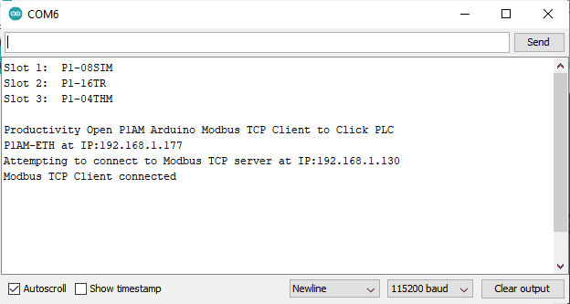
If everything is working correctly you will receive the following message. Modbus TCP Client connected.
Click Communication Heartbeat Program
A heartbeat program will look to see if communication is still working on our port.
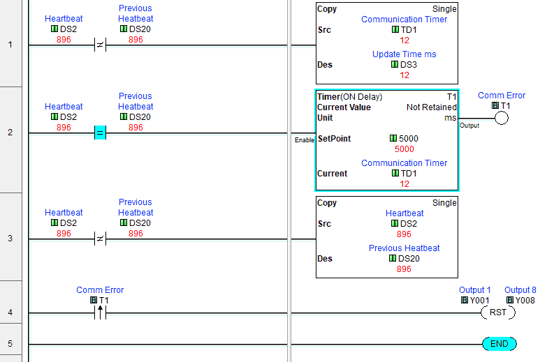
Rung 1 of our program indicates that if the Heartbeat register (DS2) is not equal to the previous heartbeat then move the timer 1 value into DS3. DS3 will show us the response time of our program in milliseconds. (12-13 milliseconds to write two holding registers and eight coils on the network.)
Rung 2 is our timer. This will keep track of how long the heartbeat and previous heartbeat values have been the same. If the timer 1 time out then we know that 5 seconds (5000 ms) have expired and we do not have communications.
Rung 3 will set the previous heartbeat to the current heartbeat. This allows the timer to start timing again.
Rung 4 uses timer 1 done bit to determine when we no longer have communication. When this happens, the output bits will be reset.
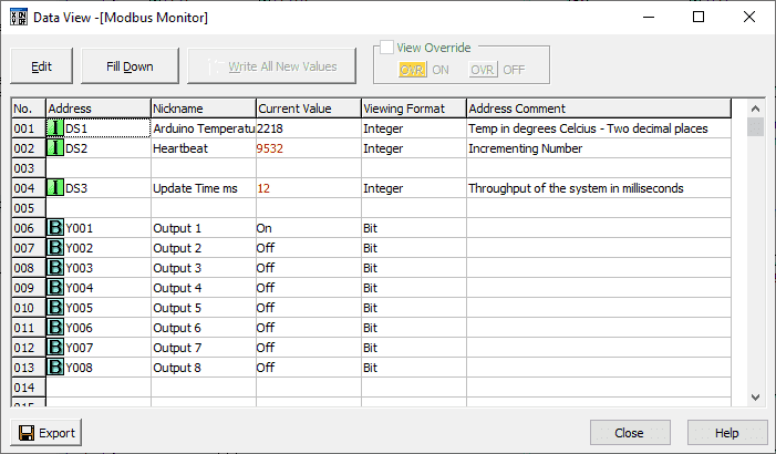
Arduino Click Modbus Communication Testing
The data view in the Click PLC programming software will show the values of our coils and registers.
When we disconnect the Ethernet cable from our Arduino P1AM the serial monitor will show an error.

Five seconds after the cable is unplugged, the Click outputs that we were controlling will turn off.
Watch the video below to see the operation of our productivity open industrial Arduino controller communicating Modbus TCP to our Click PLC controller.
Download the P1AM-100 sample sketch and Click PLC programs here.
Productivity Open Arduino Compatible Links:
Product Hardware
– Productivity Open (Automation Direct)
– P1AM-100 Specifications
– Productivity Open User Manual
– Configure a Productivity Open Arduino-based Controller
– Open Source Controllers (Arduino-Compatible)
– Productivity Open Documentation (Facts Engineering)
– P1AM Design Files
Software
– Arduino IDE (Integrated Development Environment)
– P1AM-100 library (Easy Interface for controlling P1000 Modules)
– Productivity Blocks (Development Timesaver)
– Productivity Blocks Documentation (Wiki)
Community
– Automation Direct Forum – Open Source Devices
Modbus Learning Links:
Simply Modbus Frequently Asked Questions
Modbus TCP/IP Overview – Real-Time Automation
All You Need to Know About Modbus RTU – Video
This concludes our P1AM-100 Arduino Industrial Controller series. We will be adding additional posts based on questions, comments, or new hardware.
Thank you.
Watch on YouTube: Productivity Open P1AM Arduino Modbus TCP Client to Click PLC
If you have any questions or need further information please contact me.
Thank you, Garry
If you’re like most of my readers, you’re committed to learning about technology. Numbering systems used in PLC’s are not difficult to learn and understand. We will walk through the numbering systems used in PLCs. This includes Bits, Decimal, Hexadecimal, ASCII and Floating Point. To get this free article, subscribe to my free email newsletter.

The ‘Robust Data Logging for Free’ eBook is also available as a free download. The link is included when you subscribe to ACC Automation.