
Suppanel is an Android app that is used to create a human machine interface (HMI). This HMI panel can be created on your computer, tablet or phone using the appropriate operating system or software. You can use this software to create panels that you can control or modify values in your automated system. These panels can be shared with other Suppanel users.
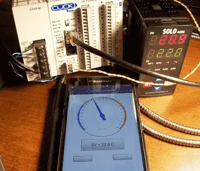
We will be creating a Suppanel Panel to monitor and control a Solo Process Temperature Controller via the Click programmable logic controller (PLC). The Click will be communicating to the Solo with serial RS485 using Modbus RTU protocol. The Suppanel HMI will be communicating to the Click PLC using Ethernet Modbus TCP protocol.
Watch on YouTube : Suppanel Android HMI to Click PLC
Let’s get started.
Andriod Suppanel Installation
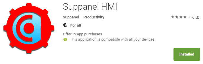
Install the Suppanel software on your android device. The software requires android 4.1 or higher versions. A 60 day trial is automatically started when you install the software.
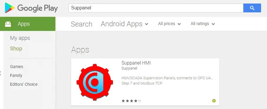
Open the Google Play Store and search for Suppanel. You can also click the link below.
https://play.google.com/store/apps/details?id=com.suppanel.suppanel&hl=es
If you are running on a windows machine, you can use your chrome browser and run ARC Welder to run the Suppanel application.
https://developer.chrome.com/apps/getstarted_arc
This is the method that we are using in the video below to demonstrate our communications to the Click PLC.
Note: ARC Welder will not allow In-App Purchases so you will only have 60 days for a trial period.
Click PLC Program
We will be using a modified version of the program that we demonstrated the send and receive commands in the click. Here is the post that will describe the setup of the Solo process temperature controller and the Click PLC.
https://accautomation.ca/click-plc-send-and-receive-instructions/
The communication to the solo uses port number 3 (RS485). This is a twisted pair serial communication with the Modbus RTU protocol.
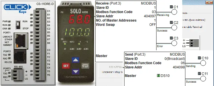
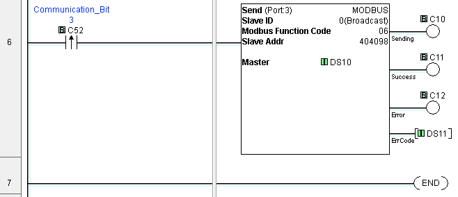
Here is our program:
Click PLC Communication to Solo Process Temperature Controller
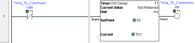
Set up the time for each of the communication instructions to be executed.
In our case 50 ms timer is used.
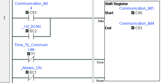
Communication Timing Sequence
We use a shift register that will self reset. This way we ensure that only one bit is on at a time for our communication. The bit get shifted based on the timer T1 above.
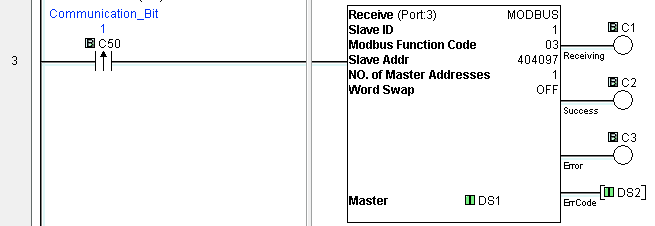
Process Value (PV) read from the Solo
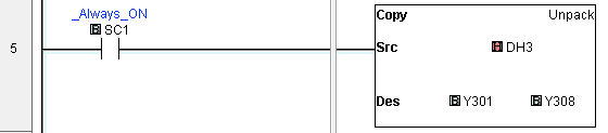
LED Status read from the Solo
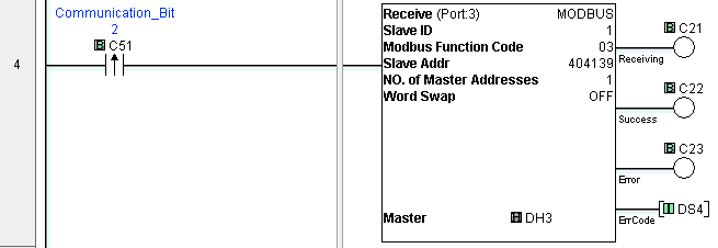
Y301 to Y308 represent the LED status of the Solo
Bit 0 – Y301 – ALM3
Bit 1 – Y302 – ALM2
Bit 2 – Y303 – F degrees
Bit 3 – Y304 – C degrees
Bit 4 – Y305 – ALM1
Bit 5 – Y306 – OUT1
Bit 6 – Y307 – OUT2
Bit 7 – Y308 – AT (Auto Tuning)
Set Point Value write to the Solo
Place the Click PLC in run mode. You should have communications between the Click and the Solo process temperature controller.
IP Address of the Click PLC
To see the IP address of the Ethernet port on the Click, select from the main menu | Setup | Com Port Setup…
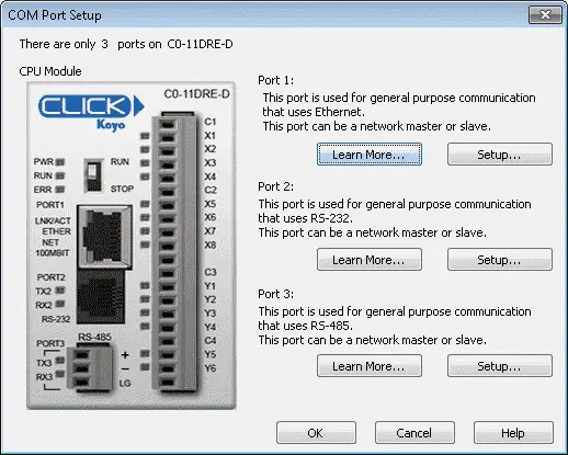
Select Setup on Port 1 (Ethernet)
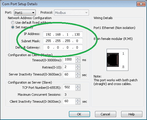
We can see that the IP address is set for 192.168.1.130.
Modbus Addresses of the Click PLC (192.168.1.130)
Select Address Picker under the Ladder Program of the Navigation window.
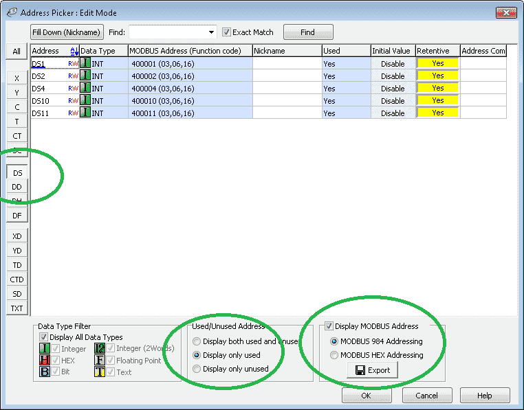
Click Display MODBUS Address (MODBUS 984 Addreessing)
Click Display only used addresses
Click the DS memory area.
You can now see the addresses that we will need for our Suppanel Panel.
DS1 – Current present value (PV) – 400001
DS10 – Set point value (SV) – 400010
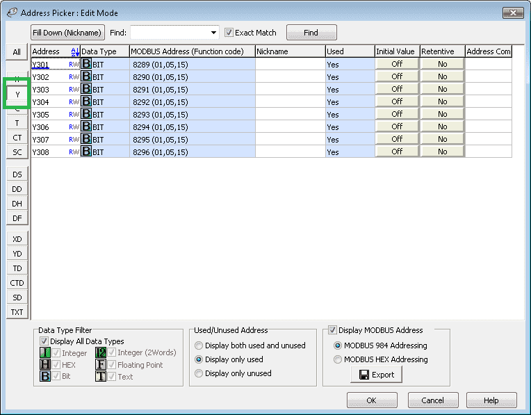
Select the Y area on the address picker. These are the addresses for the Solo LED status.
Android Suppanel Panel Creation
Start the Suppanel program.
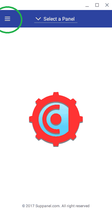
Select the menu on the left. (Main Menu)
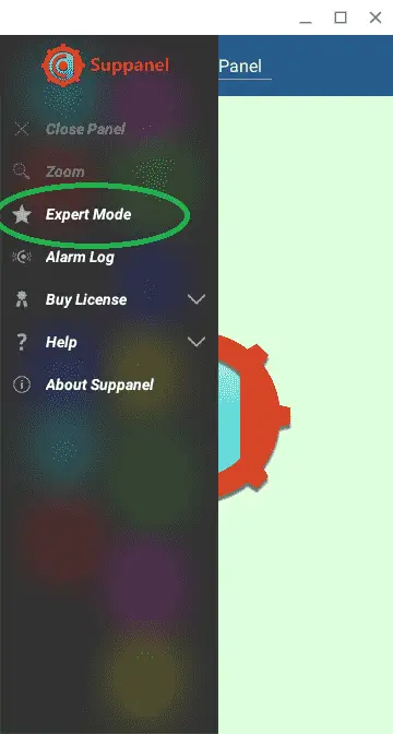
Select “Expert Mode”. This is the mode that we need to be in to create a new panel.
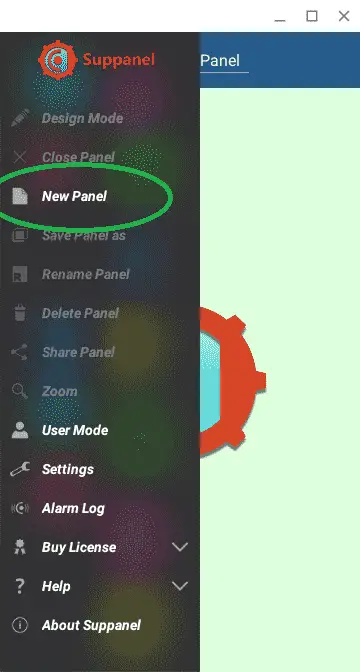
Our left hand menu has now changed to reflect our Expert Mode.
Select “New Panel”

Enter the panel name. In our case we will call the panel “Click PLC – Solo Control”
Hit OK
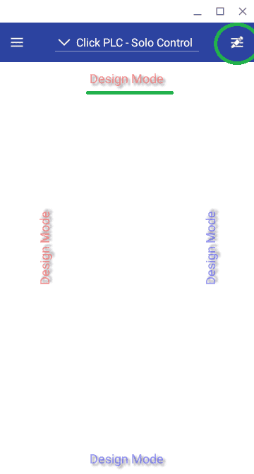
We are now in Design Mode. Notice that we have a right hand menu now on our screen. This is the design menu.
Select the design menu.
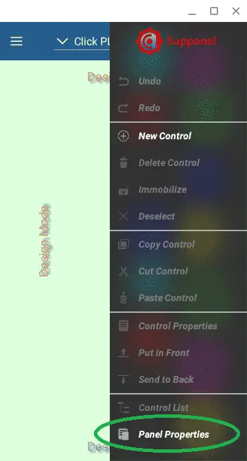
Select Panel Properties
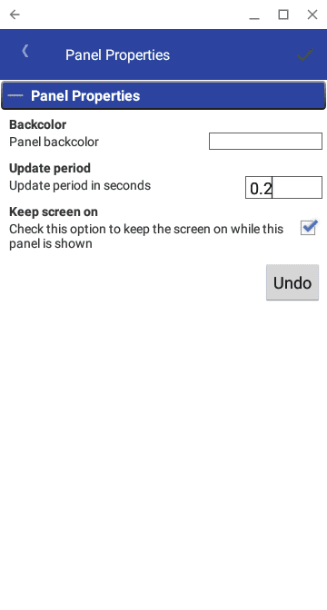
The following items can be changed on your panel.
Backcolor – This is the background colour of the panel. The default is white.
Update period – This is the amount of time in seconds before the panel will update the information. The default is 1.0 seconds. We have changed this to 0.2 seconds so our panel is more responsive.
Keep Screen On – When the panel is showing the screen will remain on. It will not go into a sleep mode.
Click the green check mark in the top right corner to go back to the design menu.
Select the design mode menu.
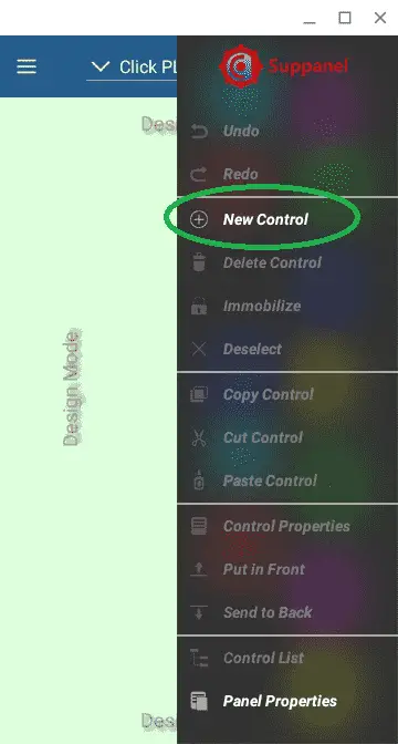
Select new control.
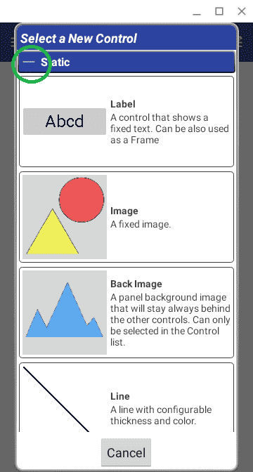
Click the Static area to minimize the menu.
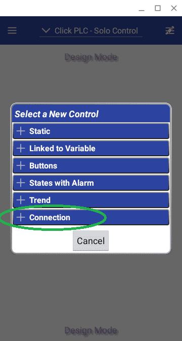
We now see all of the options for the new control. The first thing that we need to do is to set up the connection to our Click PLC. Select the Connection option.
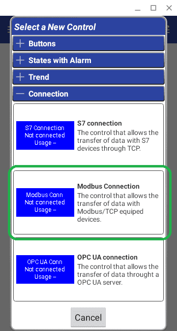
Select the Modbus Connection
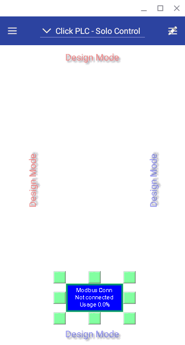
The control is then put on our panel. We can move the control around the screen by selecting and holding the control and moving it around the screen. You can also resize the control by selecting any of the green boxes around it and dragging it.
Double click on the control or while the control is selected call up the design menu and select control properties.
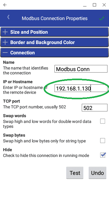
Enter the IP address of the Click PLC. The default port 502 for Modbus TCP is automatically selected.
Click the Test button to ensure that we have communication to our Click PLC.
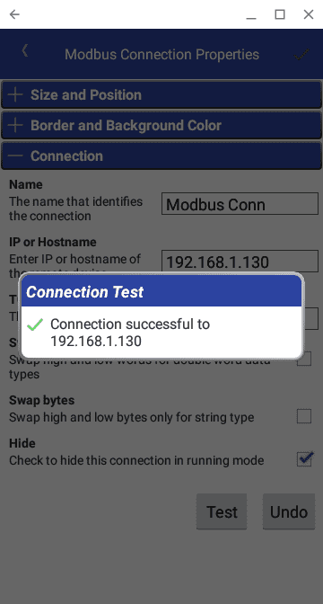
Select the green check mark at the top of the Modbus Connection Properties to return to the design screen.
Suppanel HMI – PV value display
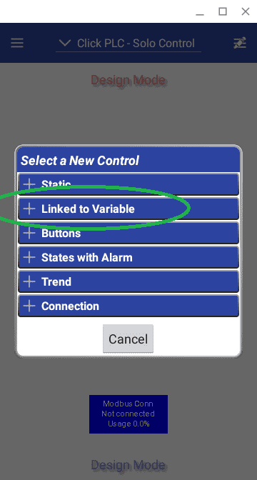
From the design menu select a new control. We will now add a linked to variable control.
Select Linked to Variable
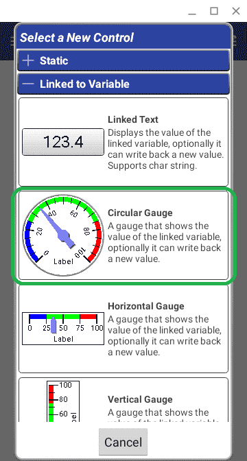
Select the circular gauge.
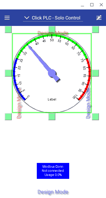
We can resize this control on the screen. Now double click or select control properties from the design menu.
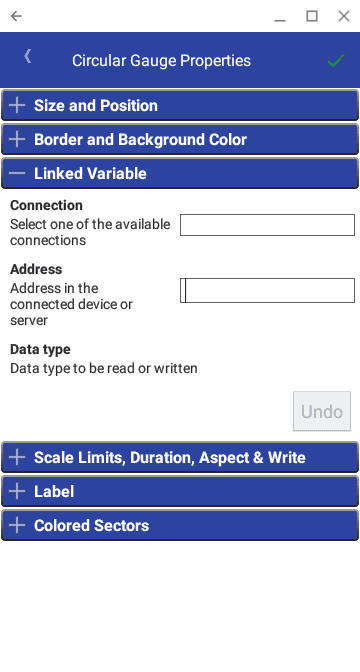
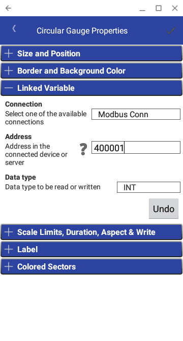
Under the linked variable properties, change the connection to Modbus Conn. The Modbus Address of Solo PV value can be entered 400001. The Data type will be left as INT (Integer)
Select Scale Limits, Duration, Aspect and Write properties.
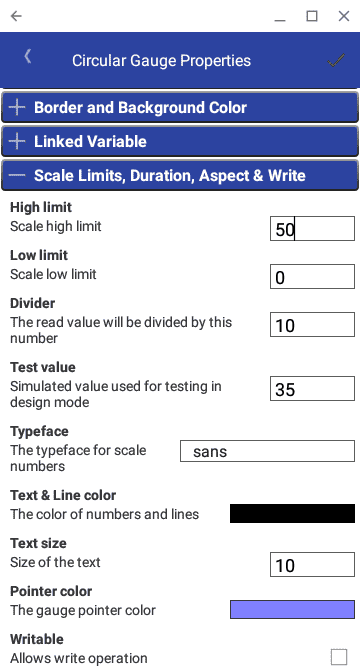
We will change the High Limit scale to 50 from 100. Change the Divider from 1 to 10. The numbers being read are to one decimal place. A value of 180 is equal then to 18.0 or 18.
Select the Label properties
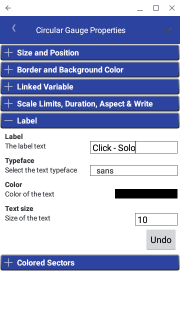
Change the label to “Click – Solo”
Select the Colored Sectors.
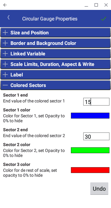
Change the end value of the colored sector 1 to 15.
Change the end value of the colored sector 2 to 30.
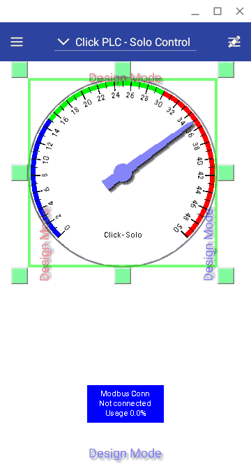
Click the green check mark at the top of the properties window to return to the design screen. You will see the changes that we have made to our control.
Suppanel HMI – SV display
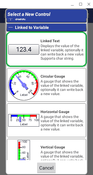
Select a new control from the design menu. Under the Linked to Variable, choose the Linked Text.
You can then resize the control on the panel.
Double click the new control to bring up the control properties. Alternatively, while the control is selected select the design menu and select Control Properties.
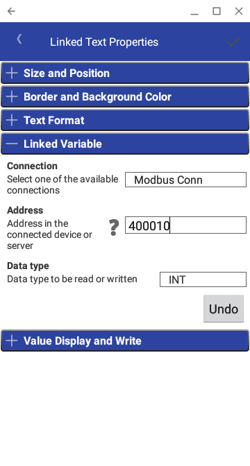
Set the following under Linked Variable:
Connection – Modbus Conn
Address – 400010
Data Type – INT
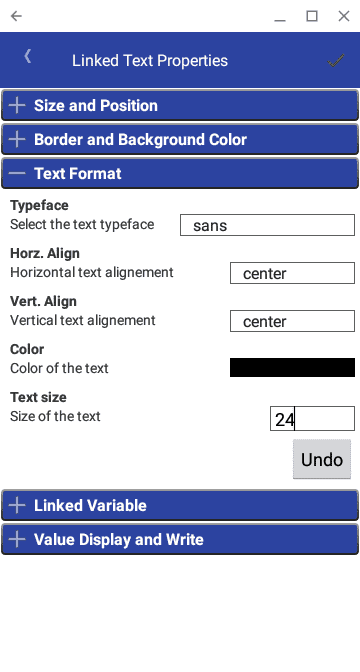
Set the following under Text Format
Text Size – 24
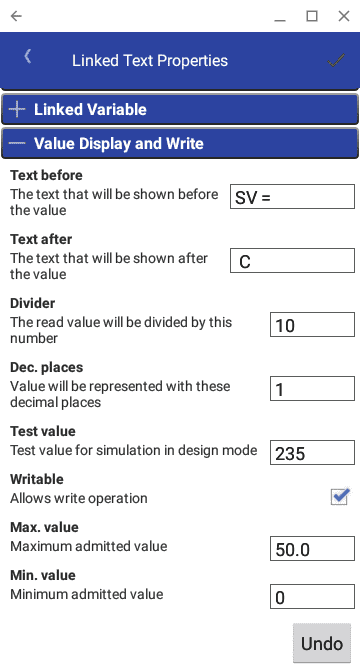
Set the following under Value Display and Write
Text before – SV =
Text after – C
Divider – 10 (The values read have one decimal place. The value read must be divided by 10.)
Test value – 235. This can be any number that will represent the number being read.
Writable – This must be selected in order to write the number to the PLC.
Max. value – 50.0 This is the maximum number that can be written into the variable. This is the maximum of our gauge programmed above.
Min value – 0 This is the lowest value to be written into the variable.
Select the check mark in the top right corner to close the link text properties.
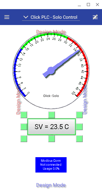
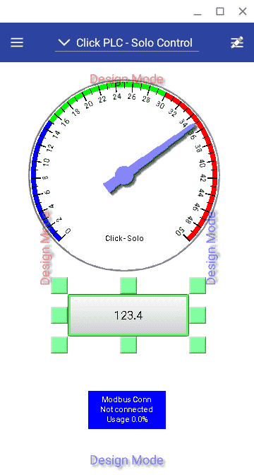
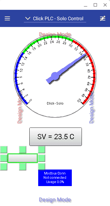
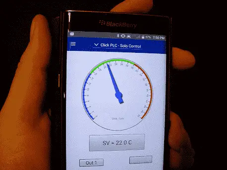
Our screen now shows our present value through the gauge and the set value through the linked text display.
Suppanel HMI – Output 1 and Output 2 display buttons
The Solo controller has outputs that we can determine if they are on or off. This could also be alarms that can be monitored.
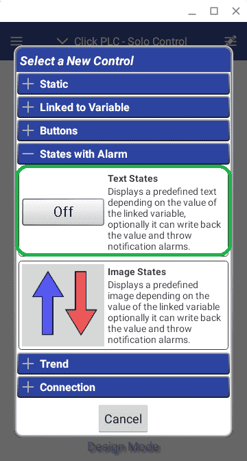
Select New Control from the design menu. Choose the States with Alarm and select Text States.
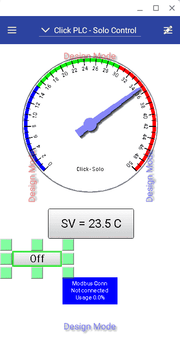
Position the control on the screen. Double click it or select Control Properties from the design menu to bring up the properties.
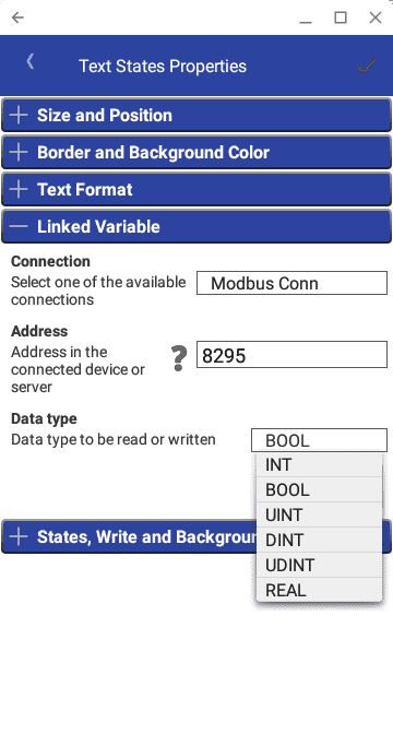
Under the Linked Variable in the Text States Properties set the following:
Connection – Modbus Conn
Address – 8295
Data Type – BOOL
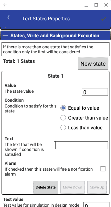
Under the States, Write and Background Execution set the following:
State 1 – Text – Blank – The default is the word off.
Click New State
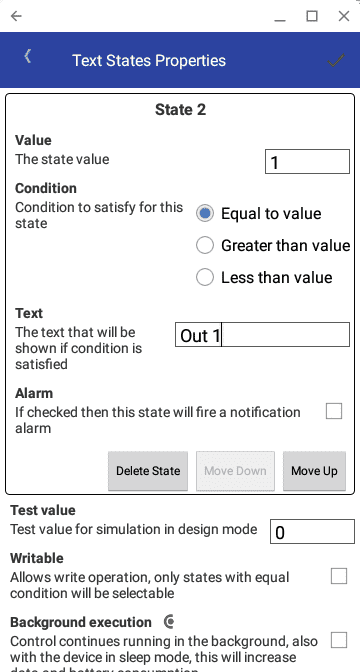
State 2 – Text – Out 1 – This means that when the value of 1 (on) appears then the message Out 1 will appear.
You will notice that each state will have an alarm. If this is checked then the device will activate an alarm when activated.
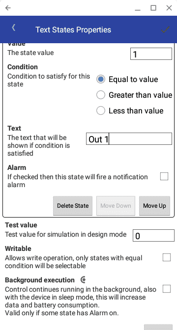
Test Value – This is the value in design mode
Writable – This indicates if the value can be changed.
Background execution – When this is set, the HMI is constantly looking for the alarms that are set and will react. This happens even when the device is in sleep mode.
Click the green check mark to return to the design screen.
We will now copy our previous control and modify the settings so it will control Out 2.
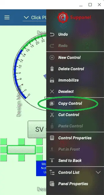
While the control is selected, select Copy Control from the design menu.
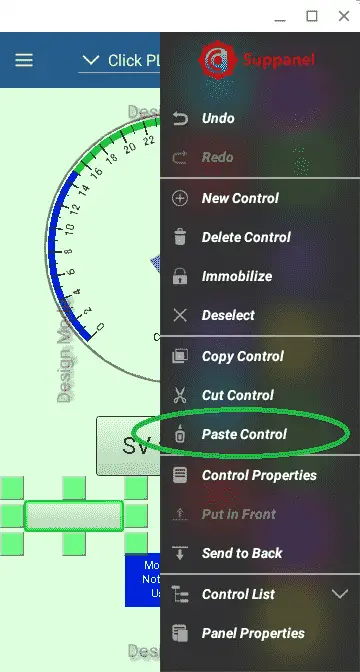
You will notice now that the Paste Control can be selected. Select the Paste Control.
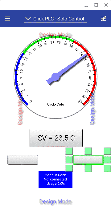
Position the control on the design screen. Select the properties for the control. (Double click or select Control Properties from the design menu.)
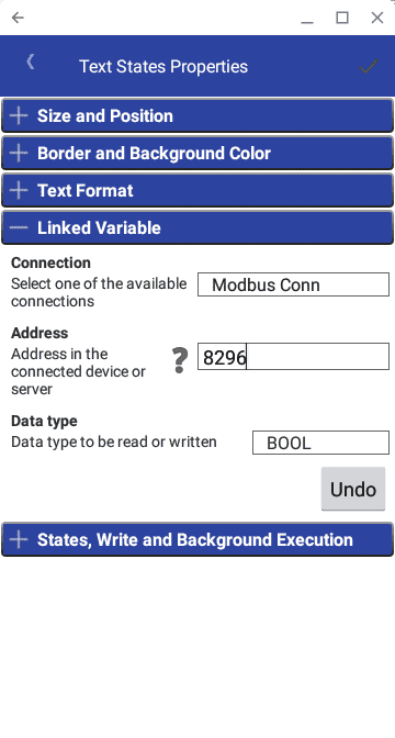
Change the Address under the Linked Variable to our new value of 8296.
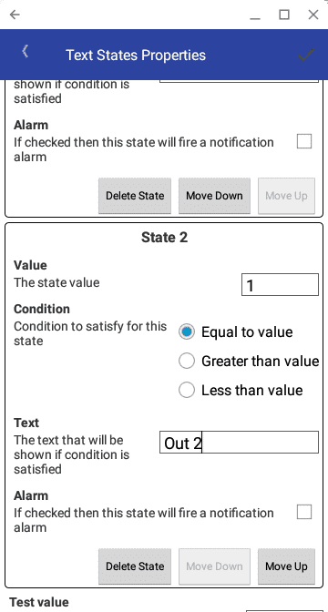
Change the State 2 Text to Out 2.
Click the green check mark on the top right corner of the Text States Properties.

We have now finished the design of our Suppanel HMI.
Run our Android Suppanel HMI to Click PLC Program

We are currently in Design Mode. (Expert Mode) Call up the main menu on the left side.
To run our panel, select Run Panel. You can also change to User Mode. This will automatically run your panel.
Suppanel HMI – Errors
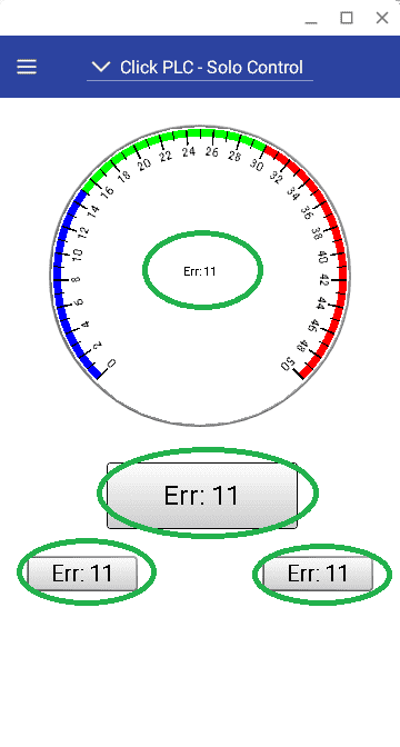
If you experience errors on the HMI, then take note of the particular error. In our case the (Err: 11) is showing on our display.
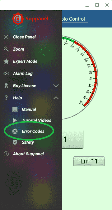
Select the Error Codes under the Help option on the main menu. This will show you all of the error codes.
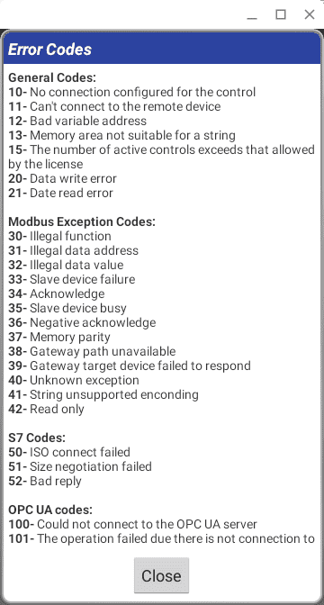
Our error above is 11 – Can’t connect to the remote device. We can then check to see if the device is on and connected to the network.
Watch the video below to see how easily it is the use the Suppanel Android HMI unit with the Click programmable logic controller.
Download the Click PLC, Suppanel HMI programs here.
Suppanel Website
http://www.suppanel.com
Manual:
http://www.suppanel.com/index.php/en/support-en/manual-en
Google Play Download:
https://play.google.com/store/apps/details?id=com.suppanel.suppanel&hl=es
Watch on YouTube: Suppanel Android HMI to Click PLC
If you have any questions or need further information please contact me.
Thank you,
Garry
If you’re like most of my readers, you’re committed to learning about technology. Numbering systems used in PLC’s are not difficult to learn and understand. We will walk through the numbering systems used in PLCs. This includes Bits, Decimal, Hexadecimal, ASCII and Floating Point.
To get this free article, subscribe to my free email newsletter.
Use the information to inform other people how numbering systems work. Sign up now.

The ‘Robust Data Logging for Free’ eBook is also available as a free download. The link is included when you subscribe to ACC Automation.