Receive and Send instructions will allow you to send and receive serial data to an external device. The communication method that you setup can be ASCII or Modbus. ASCII (American Standard Communication for Information Interchange) can be used to send to devices such as a printer. Receiving ASCII can be used for connecting barcode scanners to the PLC. The barcode will be read as an ASCII string in the PLC. Modbus serial communication (Modbus RTU) is a standard protocol used in many automation devices. We will demonstrate the Send and Receive instruction by communicating Modbus to a Solo Temperature Controller. Our example will read the current process (PV) value and write the set point value (SV) in the controller.
Previously in this Click PLC series we have discussed:
System Hardware – Video
Installing the Software – Video
Establish Communication – Video
Numbering System and Addressing – Video
Timers and Counters
– Counter Video
– Timer Video
Compare and Math Instructions – Video
Program Control Instructions – Video
Shift Register – Video
Drum Instruction – Video
The programming software and manuals can be downloaded from the Automation Direct website free of charge.
Solo Settings – Click Send and Receive Instructions
The first thing that we will do is set up the Solo Temperature Controller. Additional information can be found at the following link.
https://accautomation.ca/solo-process-temperature-controller/
Wiring diagram:

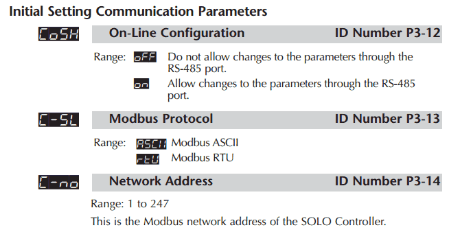
The solo process temperature controller needs to be setup before we can communicate to it. The default setting is ‘Off’ for the On-Line Configuration. Here is the way to change into the different modes in the Solo.
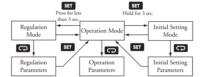
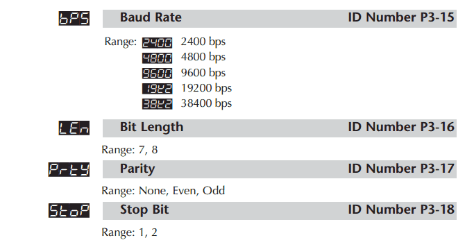
In the Initial Setting Mode we will change the online configuration to on and make the changes to the Modbus settings as follows: 9600 Baud, Even, 7 Data Bits, 1 Stop Bit, Modbus ASCII Format. We will leave the default unit number as 1.
Our controller is now set to communicate.
Download the documentation and/or configuration and monitoring software at the following URL link:
http://support.automationdirect.com/products/solo.html
Modbus RTU Serial Network
Modbus RTU will be the serial (RS485) method in which we will communicate between the Click PLC Port #3 and the Automation Direct Solo Process Temperature Controller.
We can address up to 247 (Solo 1 to 247) devices on this master–slave protocol. A maximum of 32 devices (Nodes) on the network can communicate to the master. A review of the Modbus RTU protocol can be seen at the following URL.
http://www.rtautomation.com/technologies/modbus-rtu/
Click PLC Receive Instruction
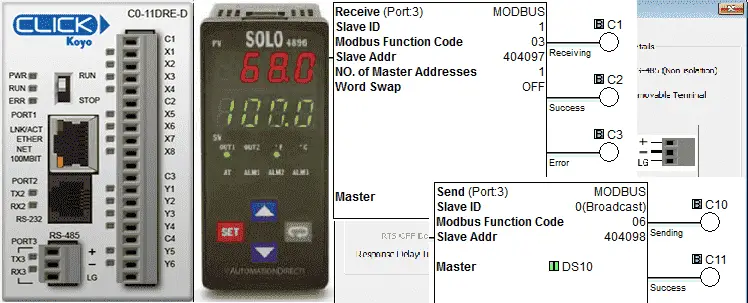
Let’s look at the Click PLC Receive Instruction and the information that we need to provide.
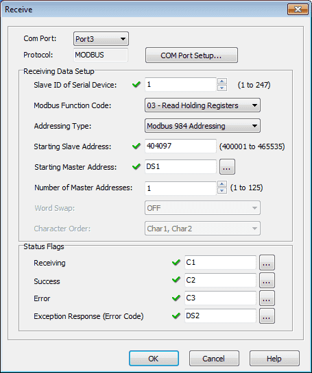
Com Port – Click the arrow to display a list of the communication ports available on the PLC. The default is Port2. We will change this to Port3.
Protocol – This is the communication language that will be used on the communication port. We have Modbus and ASCII. To change this setting go to Com Port Setup…
Com Port Setup… – This will open the Com Port Setup Details window.
We can set the protocol type of the communication port as well as all of the parameters.
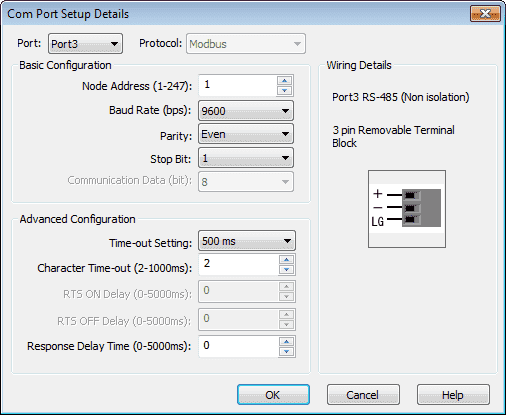
The parameters listed here must match what we set on the solo process temperature controller. Node Address 1 – 9600 baud, Even parity, 1 stop bit, 8 data bits. We can leave the advanced configuration to the default settings.
Receiving Data Setup
Slave ID of Serial Device – This is the node address of the slave that we wish to communicate. In our case, we have the node address set to 1.
Modbus Function Code – We can select one of the four Modbus function codes. In our case, we will select 03 – Read Holding Registers.
Addressing Type – We can select between Modbus 984, Modbus Hex, and Click Addressing. Our application will use Modbus 984 addressing which is patterned after the Modicon PLC addressing. This is supported in many devices.
Starting Slave Address – This is the address that we wish to read from the remote slave device (Solo Temperature Controller) When we selected the Modbus function code to read the holding registers it limits the address that we can enter into this location for this function code. (400001 to 465535)
Note: This must be a 6 digit number.
Looking at the Solo Modbus addressing:
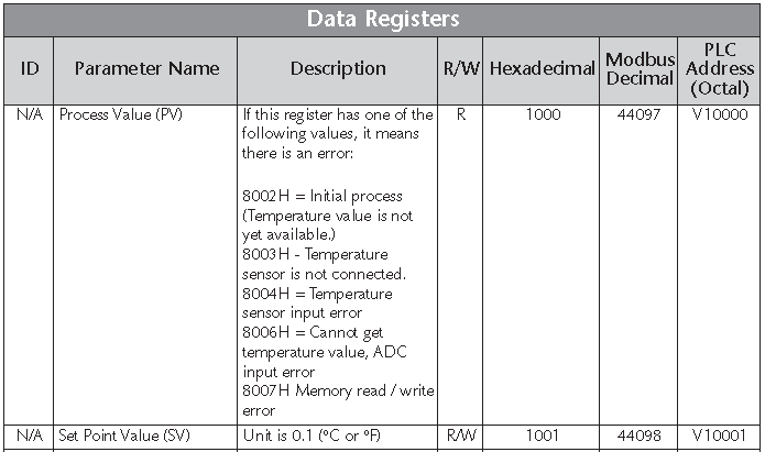
To read the PV value we must use code 4097. Therefore our address will be 404097.
Starting Master Address – This is where the information will be written in the click plc after reading the Modbus slave information.
Number of Master Addresses – We can enter the number of registers that we would like to read from the Modbus slave. In our case, we will read just the one register for the present value. (PV)
Word Swap – This is used when we read 32-bit registers from the Modbus slave and we need to switch the order in which the information is stored.
Character Order – This is not used.
Status Flags – These flags allow us to determine the status of our instruction.
Receiving – This bit that we specify will turn on when we are sending or receiving information through the communication port.
Success – This bit that we specify will turn on if the communication was successful and stay on until we enable the instruction again.
Error – This bit that we specify will turn on if the communication was not successful and stay on until we enable the instruction again.
Exception Response (Error Code) – This will specify a memory location to store any error codes when communicating to the slave.
Let’s look at this instruction in our ladder logic.
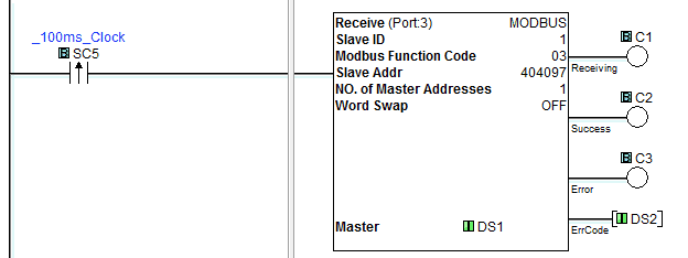
We are using the leading edge of the 0.100 ms clock pulse to enable the Receive instruction in the Click PLC. Notice that the instruction has all of the bits and register outputs that we selected when writing the instruction.
Note: If we need several receive instructions in our program then we could use the output bits to trigger the next instruction, etc.
Click PLC Send Instruction
Let’s look at the Click PLC Send Instruction and the information that we need to provide.
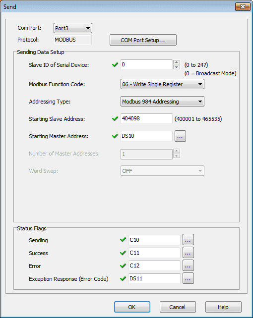
Com Port, Protocol, and ‘COM Port Setup..’ are identical to the receive instruction discussed above.
Sending Data Setup
Slave ID of Serial Device – This is the node address of the slave that we wish to communicate. In our case, we have the node address set to 0. This is a Broadcast Mode the will be sent to all slaves connected to the communication port. We could also have selected 1 to just communicate to the single Modbus slave.
Modbus Function Code – We can select one of four write Modbus function codes. In our case we will select 06 – Write Single Register.
Addressing Type – This is the same as the receive instruction above. We will select Modbus 984 addressing.
Starting Slave Address – This is similar to the receive instruction above. We are now selecting the address to write to the slave. In our case, the address for the set value (SV) will be 404098.
Starting Master Address – This is the location that the information is written in the Modbus slave will come.
Number of Master Addresses – This is the number of registers to be written to the Modbus slave. In our case, we are only writing a single register. This is why it is dimed out.
Word Swap – This is the same as the receive instruction above.
Status Flags
All of these flags are the same as the receive instruction above.
Note: All instructions in the Click have a help file that can provide additional information on the instruction that you are programming.
Let’s look at the Send instruction in our ladder program.
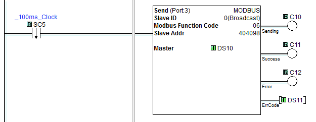
We are using the trailing edge of the 0.100 ms clock pulse to enable the Send instruction in the Click PLC. Notice that the instruction has all of the bits and register outputs that we selected when writing the instruction.
Note: If we need several send instructions in our program then we could use the output bits to trigger the next instruction, etc.
See this program in action with the video below.
Next time we will look at AdvancedHMI Communication to the Click PLC.
Watch on YouTube: Click PLC Send and Receive Instructions
If you have any questions or need further information please contact me.
Thank you,
Garry
If you’re like most of my readers, you’re committed to learning about technology. Numbering systems used in PLC’s are not difficult to learn and understand. We will walk through the numbering systems used in PLCs. This includes Bits, Decimal, Hexadecimal, ASCII and Floating Point.
To get this free article, subscribe to my free email newsletter.
Use the information to inform other people how numbering systems work. Sign up now.

The ‘Robust Data Logging for Free’ eBook is also available as a free download. The link is included when you subscribe to ACC Automation.