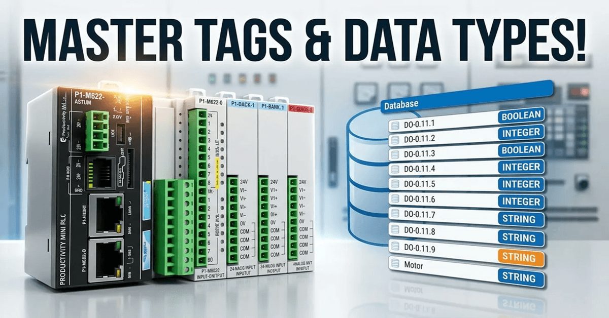
We will now look at the tag numbering systems used with the Productivity Mini PLC P1-M622-16DR. The Productivity Suite Software allows us to use tags in the PLC. Tags are a method for assigning and referencing memory locations (numbering systems) within the programmable logic controller. They allow a more structured programming approach and are stored within a tag database. The tag database is stored in the memory of the Productivity Series of PLCs from AutomationDirect. Do not overthink tags. Tags are just names that we assign to variables (numbering systems) of any data type stored in the PLC memory.
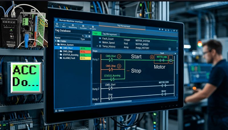
Throughout this series, we’ve been using tags like “Start”, “Stop”, and “Motor” for our start-stop circuit. These meaningful names make our program much easier to read and understand than cryptic memory addresses. In this post, we’ll explore the tag database in depth—how to create tags, understand data types, and organize our program’s memory efficiently.
Let’s get started.
Previously in this Productivity Mini PLC P1-M622-16DR series, we have discussed:
P1-M622-16DR Mini PLC System Hardware – Video
Installing the Software – Video
Establishing Communication – Video
First Program – Video
Monitoring and Testing the Program – Video
Wiring and Testing – Video
Online Editing and Fail-Safe Wiring – Video
Using the Productivity Suite Simulator – Video
Data Types – Productivity Numbering Systems
There are multiple data types available for configuring parameters and tags within your automation project. Understanding these data types is crucial for efficient memory usage and accurate data handling. Here is a list of the available types:
Boolean – True or False, 1 or 0, ON or OFF. These are used for discrete I/O point tag names as well as internal tag names used for logic control. Every switch, pushbutton, relay output, and internal flag in your program is a Boolean.
Integer, 8 Bit Unsigned – These whole or natural numbers range from 0 to 255 (0 to FF hexadecimal). They are used for numerical tags when only positive variables will be used within a byte boundary. Examples include small counters or status codes.
Integer, 16 Bit Signed – Range is -32,768 to 32,767. These are used for numerical tags where variables have the potential for negative or positive values. Useful for temperature readings that might go below zero or position offsets.
Integer, 16 Bit Unsigned – Range is 0 to 65,535. These are used for tags that will only have a positive value. Common for timer preset values or production counters.
Integer, 16 Bit BCD – Unsigned binary coded decimal will have the range of 0 to 9,999. These will be used for tags that can only be represented by the decimal numbering system. 0-9 for each digit. Often used when interfacing with older equipment or displays that expect BCD format.
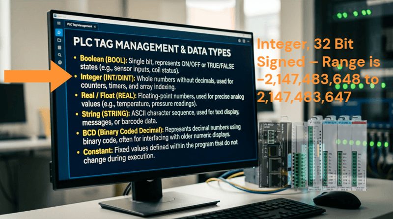
Integer, 32 Bit Signed – Range is -2,147,483,648 to 2,147,483,647. This is used as the default for most numeric tags that have the potential for both negative and positive values. The larger range makes this suitable for production counters that might accumulate large numbers over time.
Integer, 32 Bit BCD – Unsigned binary coded decimal will have the range of 0 to 99,999,999. These will be used for tags that can only be represented by the decimal numbering system. 0-9 for each digit.
Float, 32 Bit – This uses the IEEE format floating-point number ranging from -3.39×10³⁸ to 3.39×10³⁸. This data type is for tags that need decimal precision, such as analog sensor readings, flow rates, pressure measurements, or mathematical calculations requiring fractional values.
String – ASCII or text representation which allocates one byte (8 bits) per character. These are used for tags that are words when using instructions like ASCII, email, and LCD displays. Strings are essential for operator messages, part numbers, or data logging.
Constant – This is a fixed value for a numeric or Boolean tag name. Constants can be integers, floating-point or strings. When you enter the constant, the field defined by the data entered assumes the range.
Examples:
- 1 = 32 bit signed integer
- 1.0 = floating point
- A = string
For a deeper understanding of numbering systems, check out this post that explains the meaning behind the above types of numbers: https://accautomation.ca/what-everybody-ought-to-know-about-plc-programmable-logic-controller-numbering-systems/
Tag Database – Productivity Numbering Systems
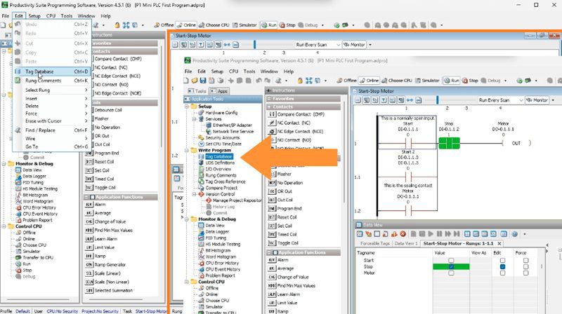
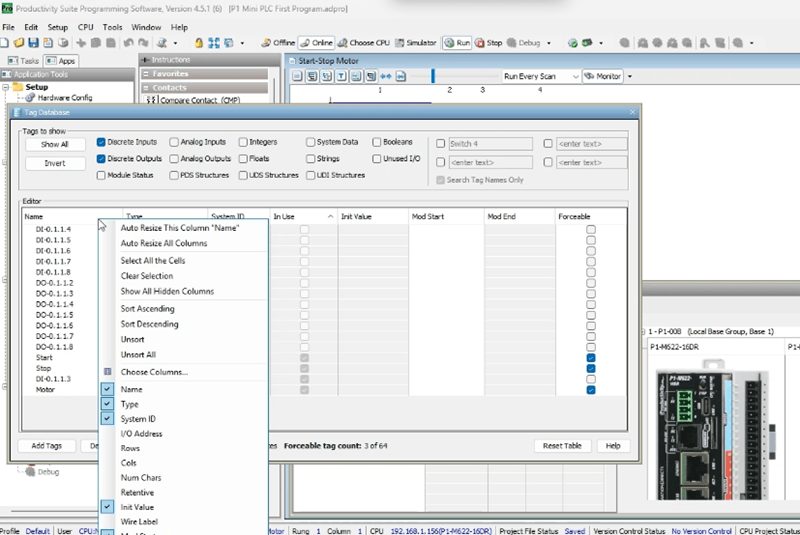
Open the tag database by clicking on the Tag Database under the Write Program heading in the Application Tools.
You can also use the main menu | Edit | Tag Database to access the tag database.
The Tag Database is the centralized location where all your program variables are defined and documented. For the P1-M622-16DR, this includes the 8 integrated discrete inputs, 8 relay outputs, and any internal memory locations you create.
Tags to Show – Productivity Numbering Systems
This upper part of the Tag Database window will help you to find the tags and information that you require quickly.
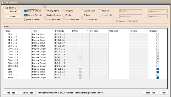
Show All – This will show all of the tags in your entire project—every input, output, internal bit, timer, counter, and variable.
Invert – This will invert all of the selected tag types. If the input type like Discrete Inputs is checked and you hit the invert button, the tag will be unchecked. If the input type is unchecked and you invert then it will be checked. This is useful for quickly switching between viewing different categories.
Search Field – The tags field will allow you to search the database for a particular name or phrase. For example, typing “Motor” would filter to show only tags containing that word.
Tag Type Filters – You can select specific categories to view:
- Discrete Inputs (your 8 built-in DC inputs)
- Discrete Outputs (your 8 relay outputs)
- Integers (all numeric variables)
- Floats (decimal numbers)
- Strings (text)
- Constants
- And many more…
For the P1-M622-16DR Mini PLC, the most commonly used filters are Discrete Inputs and Discrete Outputs since these correspond to the physical I/O built into the CPU.
Note: The P1-M622-16DR uses the addressing format DI-0.1.1.x for inputs and DO-0.1.1.x for outputs, where x ranges from 1 to 8.
Editor – Productivity Numbering Systems
The editor has the following columns of information. Not all columns may be visible by default—you can customize which ones you see.
Name – Name was given to the applicable tag. This is what you see in your ladder logic. Examples: “Start”, “Stop”, “Motor_Running”
Type – Data type used by the tag (Boolean, Integer, Float, etc.)
Str Type – Indicates the type of structure used (Single, Array, etc.)
System ID – Internal ID assigned to user-defined tags. This is managed automatically by the software.
I/O Address – The respective assigned I/O address. For the P1-M622-16DR:
- Inputs: DI-0.1.1.1 through DI-0.1.1.8
- Outputs: DO-0.1.1.1 through DO-0.1.1.8
Rows – The number of rows applicable to a 2D Array Data type
Cols – The number of columns applicable to a 1D or 2D Array Data type
Num Chars – The number of Characters applicable to a String Data type
Retentive – Checkbox indicating if the tag is retentive. If power is lost or removed from the PLC this determines if the information in the tag is retained or not. Critical for production counters and system state variables that must survive power cycles.
Init Value – Value entered in this field will be used for the initial value upon a cold start or power-up.
Wire Label – Use this field to indicate the wire label information for the I/O point. This is invaluable for maintenance—you can document which physical wire or terminal connects to each point.
Mod Start – Optional Modbus Starting Address. We specify what information can be shared on the network through Modbus communication protocols.
Mod End – Optional Modbus Ending Address
Forceable – Allows the tag to be forced using Data View. A maximum of 64 tags may be selected as forceable at any given time. We used this feature when testing our wiring in Stop mode.
Init Forced – Allows the tag to be forced upon start-up from a power cycle or stop/run transition
Init Forced Value – Value entered in this field will be used for the tag’s value upon an initial force
Comment – Use this field to add Comments associated with the tag. Detailed comments make troubleshooting much easier months or years after the program was written.
Remote Access – Checkbox that indicates the tag can be monitored remotely via the CPU Data Remote Monitor App
Default Format – Used with integers. Allows data to be viewed in various formats, i.e. decimal, hex, etc.
In Use – Checkbox indicates the tag is used in the ladder diagram. This helps identify unused tags that can be cleaned up.
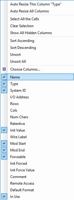
Customizing the Tag Database View
Right-clicking on the column name will bring up a menu with several options:
Auto Resize Columns – Automatically adjusts column widths to fit the content
Select Columns – Choose which columns are visible or hidden
Sort – Sort the tags alphabetically or by other criteria
Hide/Show Columns – Quickly toggle column visibility
You can also manually resize columns by clicking between column headers and dragging. Want to see tags organized your way? Simply click and drag column headers to rearrange them in any order that makes sense for your workflow.
Adding and Managing Tags
At the bottom of the Tag Database window, you’ll find several important buttons:
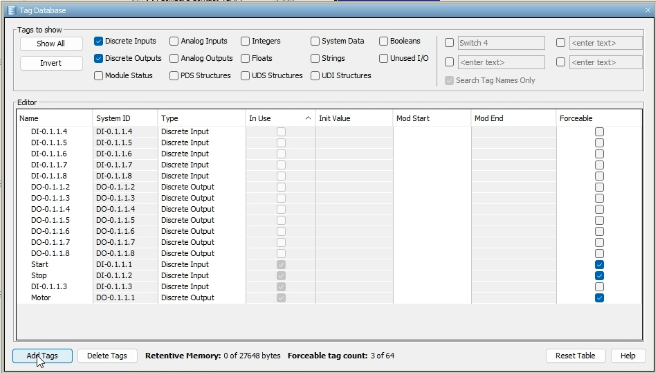
Add Tags – We can add tags of any data type. Tags can be made individually or grouped together in arrays. We will be discussing arrays and functions later in this series. When you create a new tag, you’ll be prompted to define its name, type, and initial properties.
Delete Tags – Remove a tag from the tag database. Be careful—deleting a tag that’s in use will create errors in your program until you replace it.
Reset Table – Restore the table to original default settings. This is useful if you’ve rearranged columns and want to start fresh.
Help – Explore the help menu for Tag Database. The built-in documentation is comprehensive and includes examples.
Practical Example: Understanding P1-M622-16DR Addressing
Let’s look at how our start-stop motor circuit uses the tag database:
When we configured the hardware, the Productivity Suite automatically created tags for our integrated I/O:
- DI-0.1.1.1 was automatically assigned
- DI-0.1.1.2 was automatically assigned
- DO-0.1.1.1 was automatically assigned
We then renamed these to meaningful names:
- DI-0.1.1.1 became “Start”
- DI-0.1.1.2 became “Stop”
- DO-0.1.1.1 became “Motor”
The addressing format for the P1-M622-16DR is:
- DI-0.1.1.X where X is 1-8 for the 8 inputs
- DO-0.1.1.X where X is 1-8 for the 8 outputs
The format breaks down as follows:
- First number (0) = System number
- Second number (1) = Rack number
- Third number (1) = Slot number
- Fourth number (X) = Point number (1-8)
If you expand with additional I/O modules (the P1-M622-16DR supports up to 4 expansion modules), those will have different slot numbers reflecting their position in the system.
Memory Available in the P1-M622-16DR
The P1-M622-16DR provides generous memory resources:
- User Memory: 50MB (includes program, data, and documentation)
- Memory Type: Flash and Battery Backed RAM
- Retentive Memory: 512KB
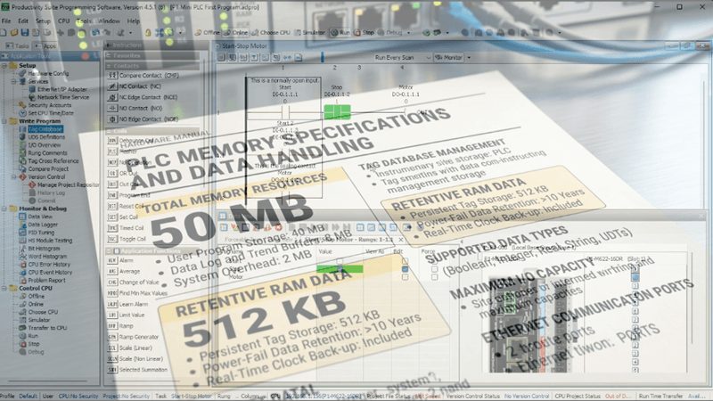
This is far more than enough for most small to medium automation applications. You could create thousands of tags and still have plenty of memory remaining. The battery-backed RAM ensures that retentive tags maintain their values even during power outages.
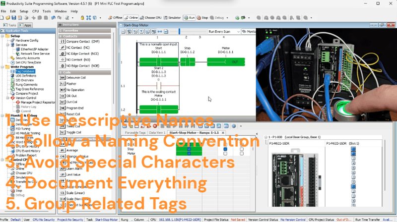
Best Practices for Tag Names
From my experience programming hundreds of PLCs, here are some recommendations:
- Use Descriptive Names – “Conv_1_Motor” is better than “M1”
- Follow a Naming Convention – Be consistent across your entire project
- Avoid Special Characters – Stick to letters, numbers, and underscores
- Document Everything – Use the comment field extensively
- Group Related Tags – Consider prefixes like “Conv_” for conveyor-related tags
The tag database allows you to manipulate and view all of the system and personal tags that you have developed. Mastering the tag database is essential for creating organized, maintainable programs.
Watch the video below to see the numbering systems and tag database in our Productivity Mini PLC P1-M622-16DR.
Productivity Mini PLC P1-M622-16DR from AutomationDirect
Overview Link (Additional Information on the Unit) Configuration (Configure and purchase a system – BOM) User Manual and Inserts (Installation and Setup Guides) Productivity Suite Programming Software (Free Download Link)
This software contains all of the instruction sets and help files for the Productivity Series.
Next time, we will look at contact and coil instructions in the Productivity Mini PLC P1-M622-16DR.
Watch on YouTube: Tag Database Tutorial for Automation Direct Mini PLCs!
If you have any questions or need further information, please contact me. Thank you, Garry
Related Posts:
- PLC Tag Databases Demystified: Your Programming Game-Changer
- What Everybody Ought to Know About PLC Numbering Systems
- P1-M622-16DR Mini PLC First Program
There are many PLC manufacturers offering various hardware and software. All programmable logic controllers share similar basic features. Here is how I would approach learning about basic PLCs.
Once you are familiar with the basics of the PLC, you will learn the specifics of the controller you will be programming.
This is the easiest way to learn about PLC programming.
Here are the controllers that we have covered or are covering at ACC Automation:
LS Electric XGB PLC Series
BRX Do-More Series (Do-More Designer Software + Simulator)
Productivity Series P1000 / P2000
Click PLC Series
Omron CP1H Series
Horner XL4 PLC Series
Arduino Opta PLC
The EasyPLC Software Suite is a comprehensive package that includes PLC, HMI, and machine simulator software. This allows you to make a digital twin. See below to receive 10% off this software. This PLC learning package contains the following:
Easy PLC – PLC Simulation will allow programming in Ladder, Grafcet, Logic Blocks, or Script.
HMI System – Easily create a visual human-machine interface (HMI)
Machine Simulator – A virtual 3D world with real-time graphics and physical properties. PLC programs can be tested using the EasyPLC or through other interfaces. (Modbus RTU, TCP, etc.)
Machine Simulator Lite – Designed to run on Android Devices.
Machine Simulator VR – Virtual Reality comes to life so you can test, train, or practice your PLC programming.
Purchase your copy of this learning digital twin package for less than $95 USD for a single computer installation or less than $110 USD to allow access on multiple computers.
Receive 10% off the investment by typing in ACC in the comment section when you order.
Learn PLC programming the easy way. Invest in yourself today.
Examples of PLC program development using the five steps.
Click PLC – Easy Transfer Line Programming – Video
Productivity PLC Simulator – Chain Conveyor MS – Video
Five Steps to PLC Program Development – Die Stamping
PLC Programming Example – Process Mixer
PLC Programming Example – Shift Register (Conveyor Reject)
PLC Programming Example – Paint Spraying
PLC Programming Example – Delay Starting of 7 Motors
PLC Programming Example – Pick and Place
PLC Programming Example – Sorting Station (Shift Register)
PLC Programming Example – Palletizer
If you’re like most of my readers, you’re committed to learning about technology. The numbering systems used in PLCs are not difficult to understand. We will walk through the numbering systems used in PLCs. This includes Bits, Decimals, Hexadecimal, ASCII, and Floating Points.
To get this free article, subscribe to my free email newsletter.
Use the information to educate others on how numbering systems work. Sign up now.

The ‘Robust Data Logging for Free’ eBook is also available as a free download. The link is included when you subscribe to ACC Automation.