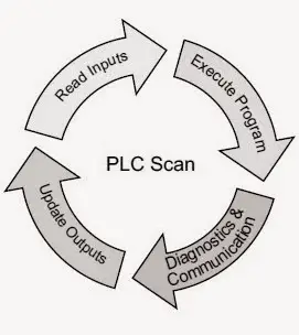
Understanding how the PLC will scan and update your program is critical in programming and troubleshooting your system. Typically a PLC will solve your logic from left to right, top to bottom. The status of the memory from the previous rung, are available for the next rung to use. We will look at a few examples to determine how the PLC will solve logic to illustrate the above program scanning.
Here are a couple of previous posts about the PLC scan and how inputs and outputs work in the PLC. This is great as a refresher before we continue our discussion.
WHO ELSE WANTS TO KNOW HOW A PLC SCANS?
HOW PLC INPUTS WORK
HOW PLC OUTPUTS WORK
We will be using the Do-more Designer software which comes with a simulator. This fully functional program is offered free of charge at automation direct.
Understanding the PLC Program Scan – Example 1
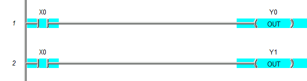
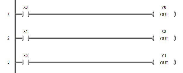
The following example looks at the input conditions when scanning your PLC program logic. Let’s look at the following rungs of logic.
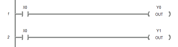
If normally open contact X0 turns on then output Y0 and Y1 will also turn on.
Now let’s put another rung in between the other two. We will have normally open contact X1 now have an output to X0. (Yes, we can control what our input contacts are doing within the PLC.)
When we turn on X0 what will happen?
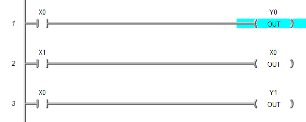
Notice that only output Y0 will turn on. This is because X1 is not on, so the second line of code changes the state of X0 to off. Note that the X0 is not highlighted because we have turned this memory bit off in the program. It will not look at the physical connection to the PLC until the end of the scan.
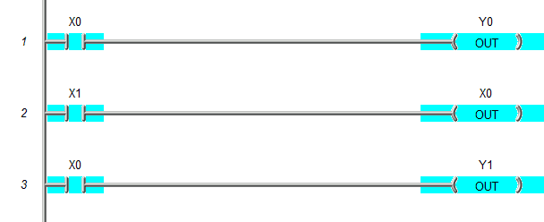
Remember that the PLC will solve the logic from left to right, top to bottom. The status of the memory from the previous rung, are available for the next rung to use.
Turning on X1 will then turn on Y1. This is independent of what X0 physically is connected and doing.
Understanding the PLC Program Scan – Example 2
Our next example will look at outputs. Physical outputs on the PLC will not be turned on until the end of the scan. NOTE: PLCs will sometimes have an instruction called I/O refresh which will immediately write and read the physical I/O during the scan.
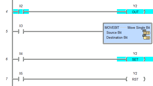
The following ladder rungs all control output Y2. We control the output in three different ways. Bit instruction, MOVEBIT, and SET/RESET are used on the same output bit.
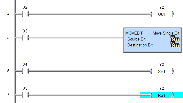
Turning X2 on/off with X3, X4, X5 off will turn Y2 on and off.
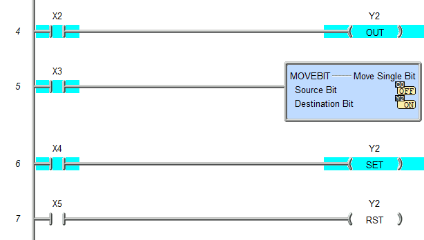
As soon as X3 is turned on with X4, X5 off then the status of Y2 is dependant on C0 bit. This is because of the MOVEBIT instruction.

X2 is now irrelevant since X3 is on.
The PLC will solve the logic from left to right, top to bottom. The status of the memory from the previous rung, are available for the next rung to use.
Now when X4 is turned when X5 is off then Y2 is set.
X2 and X3 become irrelevant to the control of Y2 when X4 is on.
X5 when on will reset Y2. All of the previous rungs will not control because the last condition during the program scan will reset Y2, so it will be off.
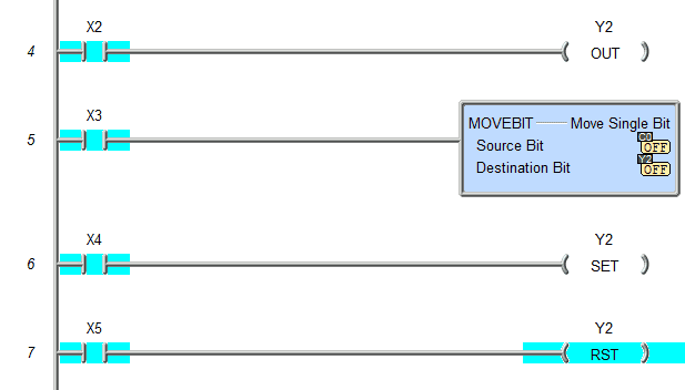
The last rung affecting the output will always control the memory bit. When troubleshooting the program logic and conditions are being met with the output not being energized it could mean that you have the above condition. Moving the rung to the end of the program logic is one way to ensure that no other conditions are affecting the operation of the output. This is one of the most common errors when programming a PLC.
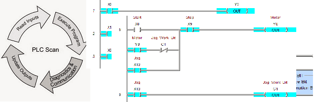
Understanding the PLC Program Scan – Start Stop Jog Circuit
Our last example will involve a start, stop and jog circuit. Here is a previous post on the subject.
HOW TO MAKE A START / STOP / JOG CIRCUIT IN A PLC
Here is our code:
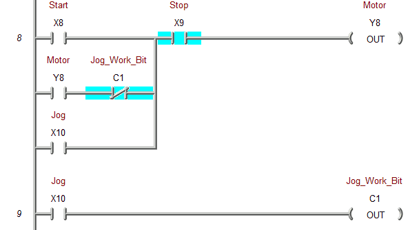
When the start input is hit we go through the stop input and the motor will turn on. The motor bit will turn on and the jog work bit is not on so the motor is sealed in and continues to be on.
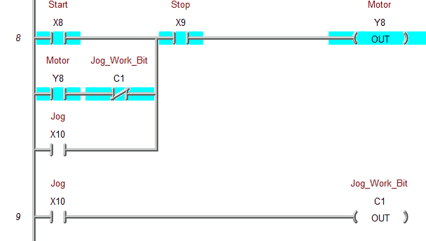
When the start input is off the motor will continue to operate.
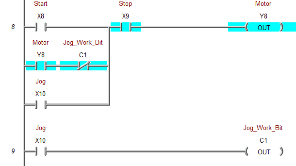
If we hit the stop input then the motor will stop and wait for the start input again.
The jog input will go through the stop and turn on the motor.
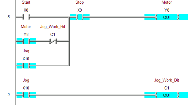
The jog input will also turn on the jog work bit output. This will open up the jog work bit in the first rung in series with the motor bit.
When the jog input turns off the motor will also turn off. This is because the jog work bit is still on until the next rung in which is gets turned off.
The PLC will solve the logic from left to right, top to bottom. The status of the memory from the previous rung is available for the next rung to use. Using this understanding will help in the program and troubleshooting your PLC program logic.
Watch on YouTube: Understanding the PLC Program Scan
If you have any questions or need further information please contact me.
Thank you,
Garry
Note:
The above works with a synchronous PLC scan. Controllers like Allen Bradley CompactLogix using the RSLogix 5000 software use asynchronous I/O scan. This means that the updating of I/O will happen whenever it can.
This means that the above circuit in an asynchronous I/O scan can have one output on and the other off if the input state changed with the input scan and the program was reading the second line. This could cause undesirable results.
In an asynchronous I/O scan, you typically will only use the actual I/O reference once in your program. Most programmers of these systems will transfer the I/O to internal memory first. They will then use the internal memory in the program code. This will now act like a synchronous, predictable scan above.
If you’re like most of my readers, you’re committed to learning about technology. Numbering systems used in PLCs are not difficult to learn and understand. We will walk through the numbering systems used in PLCs. This includes Bits, Decimal, Hexadecimal, ASCII, and Floating Point.
To get this free article, subscribe to my free email newsletter.
Use the information to inform other people how numbering systems work. Sign up now.

The ‘Robust Data Logging for Free’ eBook is also available as a free download. The link is included when you subscribe to ACC Automation.