The Arduino Opta IoT PLC allows you to conveniently program it using the Arduino PLC IDE in ladder diagram format. This is the most common industrial PLC language, a simple and intuitive method. Additionally, you can program it in any of the five official languages specified in the IEC standard and using sketches written in C++.
However, this article will solely concentrate on programming the Opta PLC using ladder logic, widely used in industrial automation and control applications. With ladder logic, you can easily design and implement logical operations by creating ladder diagrams that resemble the rungs of a ladder, making it a very effective and efficient programming technique. Let’s get started building the PLC ladder diagram.
The entire Arduino Opta IoT PLC Series is located here.
Previously in this series, we have discussed the following:
Opta Introduction Video
Arduino Opta IoT PLC Cutting Edge Hardware – Video
Arduino Opta Software Installation – Video
Arduino Opta IoT PLC Quick Start Ladder Logic – Video
Easy Steps to Establish Communication between Arduino Opta IoT PLC – Video
Arduino PLC IDE Workspace: Unleash the Power! – Video
Programming with the Arduino OPTA PLC – Ethernet Port – Video
Note: A post is usually associated with each video. This will provide additional details and links discussed.
Start a new project.
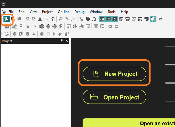
Open the Arduino PLC Integrated Development Environment (IDE) software on your computer system. Start a new project by selecting “New Project” on the main software screen.
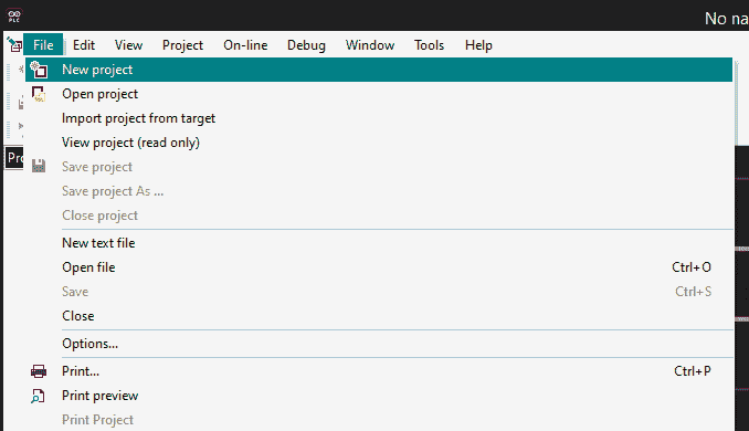
You can also select “New Project” from the main menu | File.
The third method is to select the icon for new project.
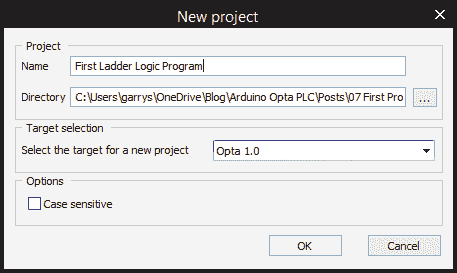
The new project window will now be displayed. Enter the name of the project in the dialog box. This will be the name of the program stored on your drive. We will leave the default directory as it is. Ensure that the Opta 1.0 PLC is selected for the target. Select OK. This will now create and save your program file for the Opta PLC.
Mapping physical I/O in the Opta PLC
The Opta has physical inputs and outputs that we will need to map before we can use them in our project.
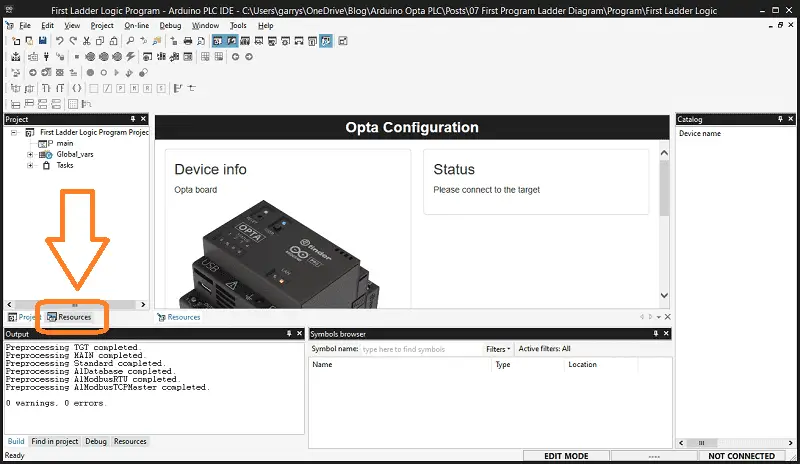
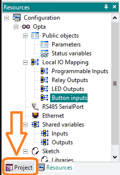
In the workspace window, select the Resources tab at the bottom.
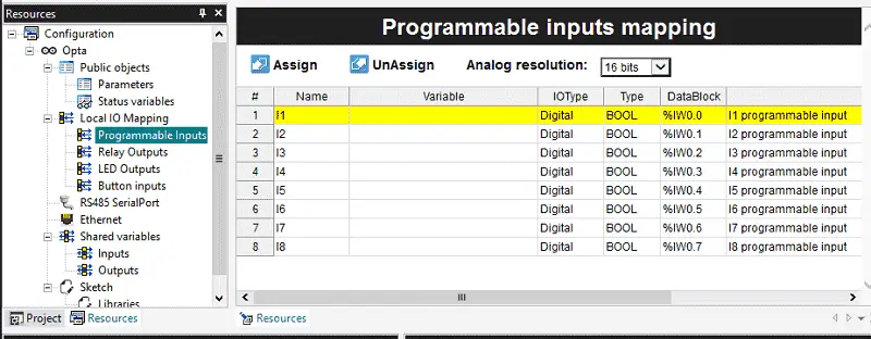
Under local IO mapping you will see all of the physical inputs and outputs on this controller. Select programmable inputs. The programmable inputs mapping will be displayed.
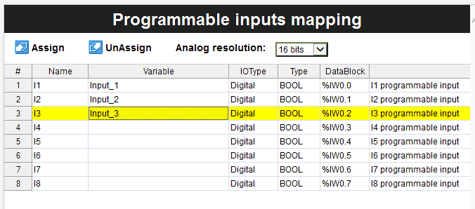
We can assign a variable to each of the inputs we intend to use in our ladder diagram.
Under IO type, we can select digital (default) or analog. The analog resolution can also be selected for the inputs.
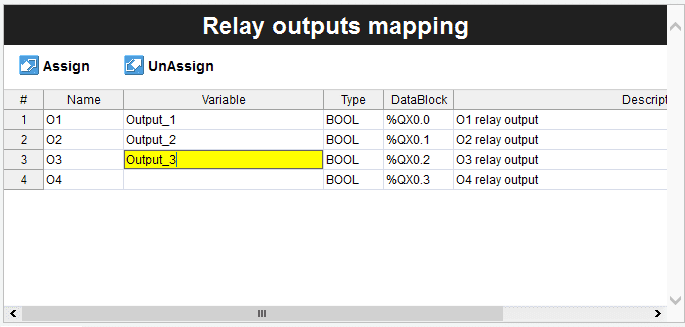
Select relay outputs that display the relay outputs mapping. We can once again assign a variable to the relays that we will use in our ladder logic program.
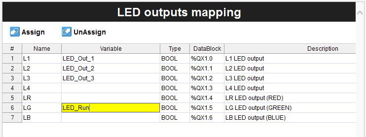
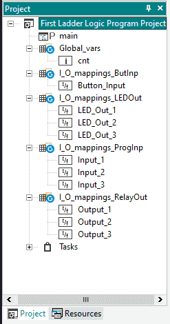
Select LED Outputs which display the LED outputs mapping. These are the status lights on the Opta CPU unit. We will make these represent the relays in our program. Assign a variable name to the three LED outputs that we will use.
The Opta PLC also has a front LED that can be different colors. We will assign the green output to indicate that the Opta PLC is working.
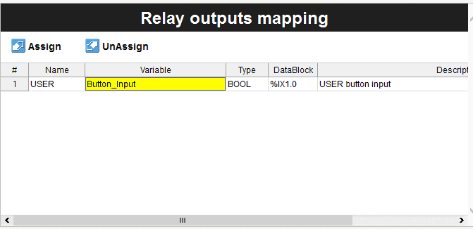
Select the button inputs to display the relay outputs mapping. We can assign a variable name to the user button input. Now that all of our mapping is complete, we can save the program using the icon on the main page. We can also save the program by using the main menu | File | Save Program.
Tasks in the Opta PLC
To access the tasks in your project, navigate to the project tab and locate the tasks folder.
You will see the list of IO that we have just mapped for this project.
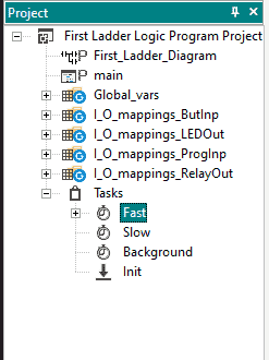
Expand the folder by clicking on the plus sign next to it. The tasks are categorized into Fast, Slow, Background, and Init.
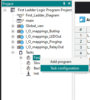
To configure the tasks, right-click on any of the four task folders and select task configuration.
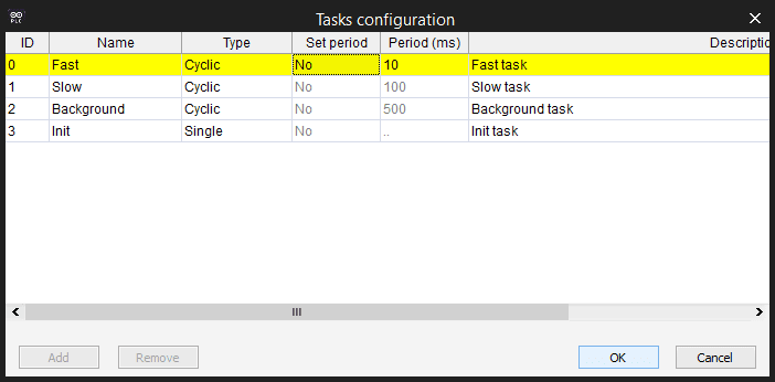
Your programs will be executed within the designated task folders.
The Fast Task folder will execute your programs cyclically every 10 milliseconds. (100 times per second)
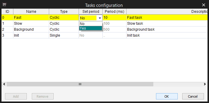
This can be changed by changing the set period to yes. You can then enter a value in the period column in milliseconds. The majority of programs will be placed in this folder.
The Slow and Background task folders will also scan cyclically. They are both set at a fixed period of 100 and 500 milliseconds. (10 times per second and two times per second) These tasks are ideal for functions like math equations, etc.
The Init or Initialize task folder sets variables or conditions in the plc after it powers up. It will run for a single scan.
Select OK to close the task configuration window.
Starting a New Ladder Logic Program
To start a new program, from the main menu select | Project | New Object | New Program.
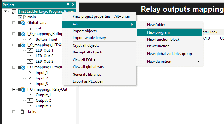
You can also do this by right click on the project name, select new program under the add heading.
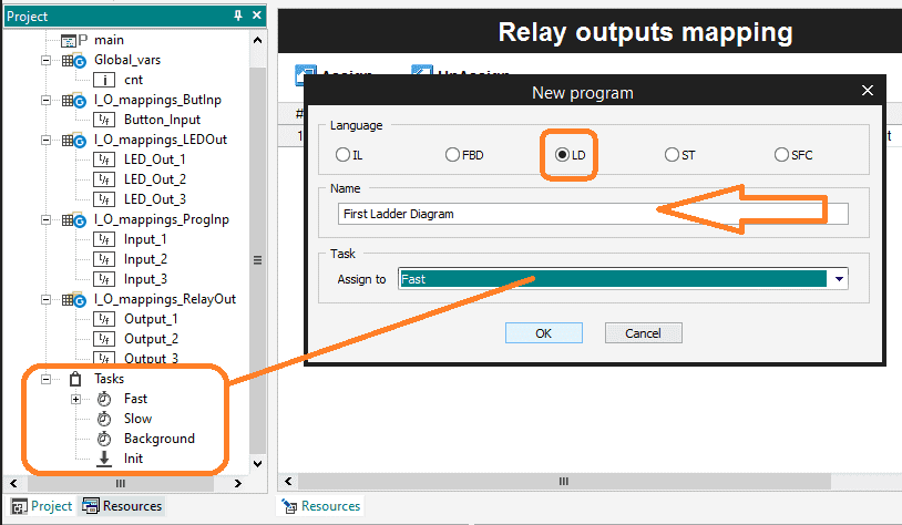
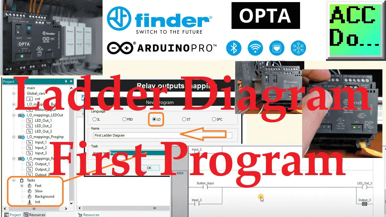
The new program window will be displayed. In our example, we will use a ladder diagram (LD).
Select LD. Name the new program Ladder and assign it to the fast task folder. Select OK.
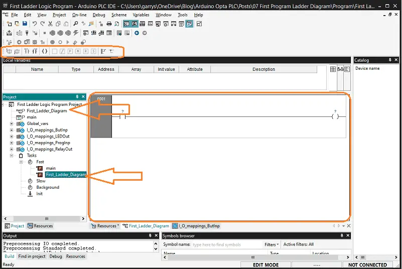
Our new ladder program will now be displayed in the work area. It will contain a single rung with an input and output condition. This program also appears under the fast task folder and the project as a ladder diagram symbol.
The ladder diagram bar icons can be displayed or hidden using the main menu | View | Toolbars| LD Bar. As you will discover, multiple ways exist to move around and enter your program.
Right-clicking on the rung number will bring up a menu to add, delete, copy, or document the rung.
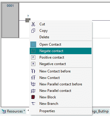
Selecting the contact and right-clicking will allow you to cut, copy, delete, change, or add additional contacts.
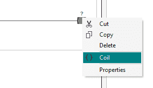
Selecting the output contact and right-clicking will allow you to cut, copy, delete, add, or view the properties of the output.
As you select the elements on the ladder rung, you will notice that the LD toolbar is also actively displaying the available options. As you highlight the toolbar icons, it will display a quick key sequence for the item.
Save the Opta PLC program.
Programming our Ladder Logic
Double-clicking on the input contacts in rung one will display the properties window.
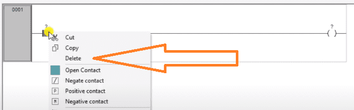
Select delete.

Double-click on the output coil in the rung. Select the three dots to the right of the name. This will call up the object browser window.
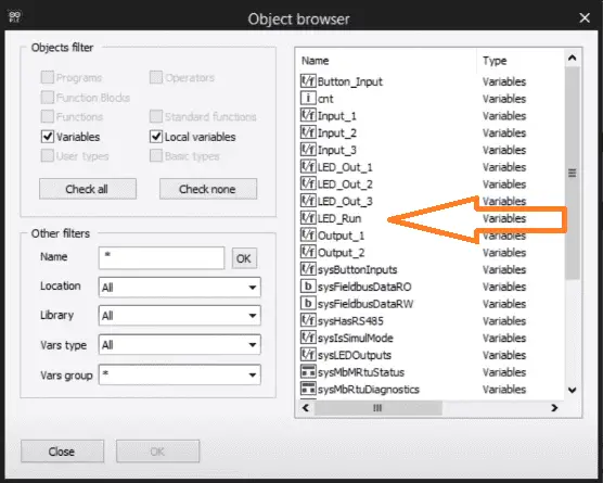
Select the LED_Run for our output coil. This will be used to indicate that our program is running. Select OK.
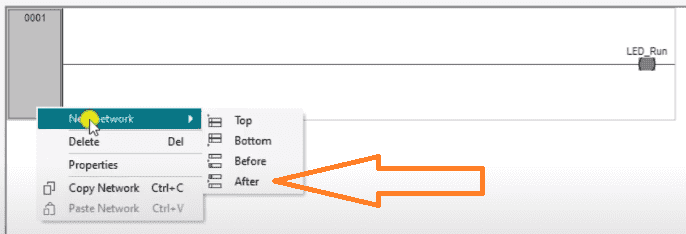
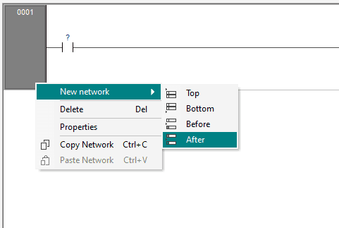
Right-click on the rung and add a new network after this rung. A new rung will be displayed as rung 2.
Double-click on the input contact. Select the three dots to the right of the name. This will call up the object browser window. Assign the input button tag.
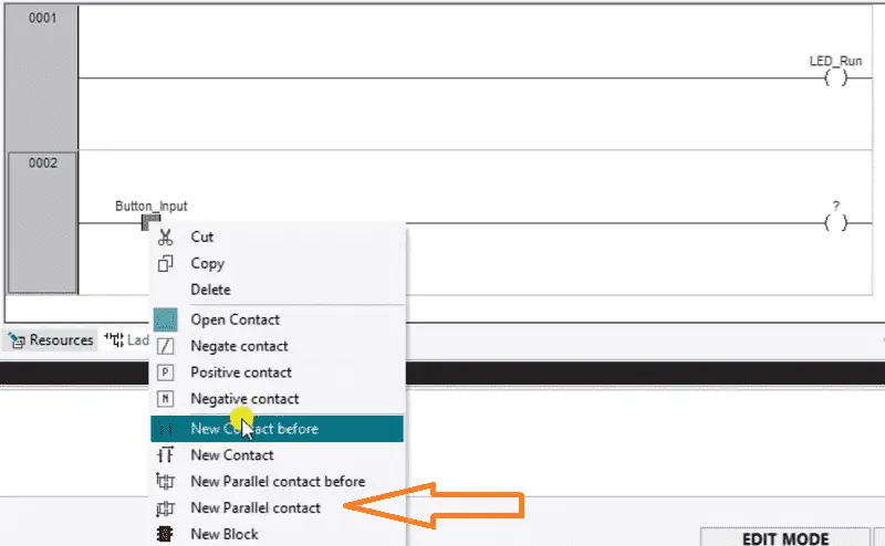
Right-click on this contact. Select new parallel contact. This will add a contact under this initial one. Double-click on this parallel contact and assign it as Input_1.
Double click on output and assign it as LED Out 1.
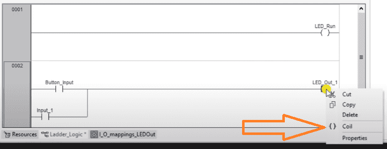
Right-click on this output and select coil. A parallel output coil will be displayed. Call this coil output_1.
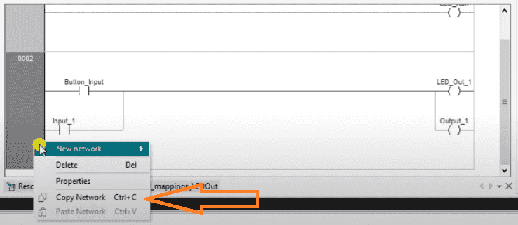
Right-click on the rung and select copy network. We could also use Ctrl+C after we selected the rung.
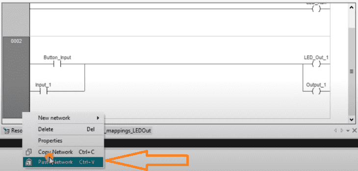
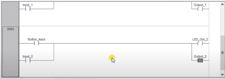
Select the rung again and right-click. Select paste network. (Ctrl + V) This will add rung 3. Change the first input and output to the second.
Copy and paste again for rung 4.
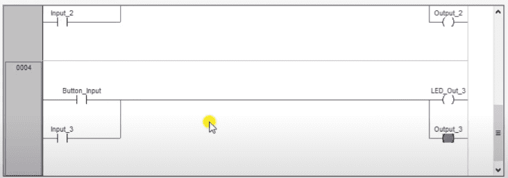
Change the input and output to three. If you forgot to include an input or output, go back to mappings and assign a variable. This must be done to include the physical IO in the program.
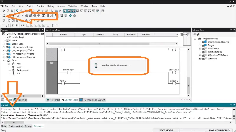
Select the compile icon on the main menu. This will compile our Opta PLC program. If there is an error, compiling will show this so we may correct it.
Download the Ladder Program to the Opta PLC
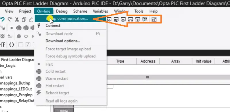
Select setup communication from the main menu | On-Line.
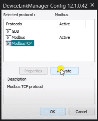
In the device link manager window, select Modbus TCP and then select activate.
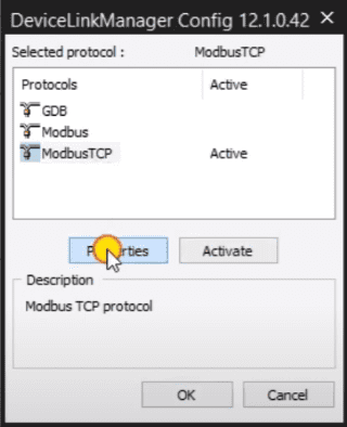
Select properties.
We can now enter the IP address we established in the following post.
Programming the Arduino OPTA PLC – Ethernet Port
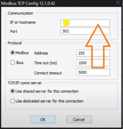
Our communication method with the OPTA PLC is now set.
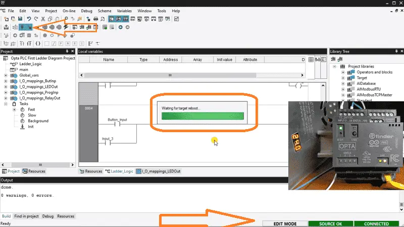
Select the connect button. We will now see that our computer is connected to the Opta PLC controller.
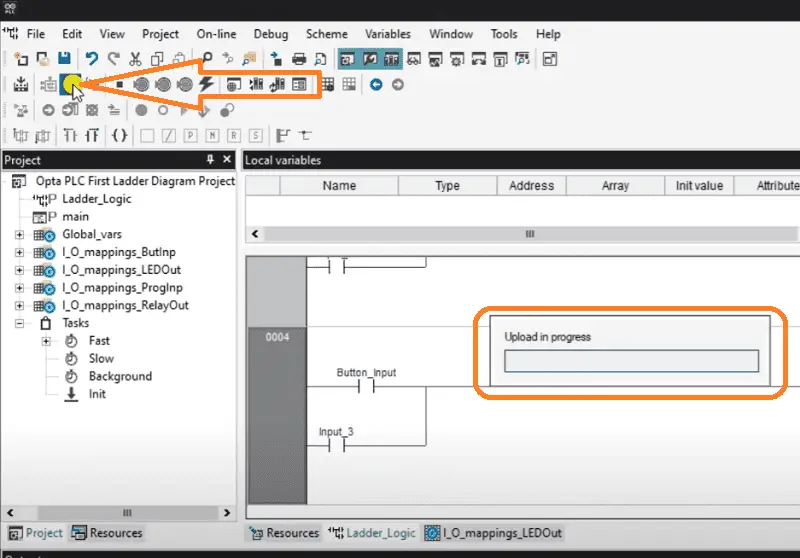
Select the download icon on the main menu.
If we didn’t compile the project first, the PLC IDE would have prompted us before downloading. Select Yes.
The output window will display the status of the download operation. When this has finished, the bottom right side of the software will show you that the PLC IDE and controller programs are the same.
Monitoring the Ladder Logic and Variables
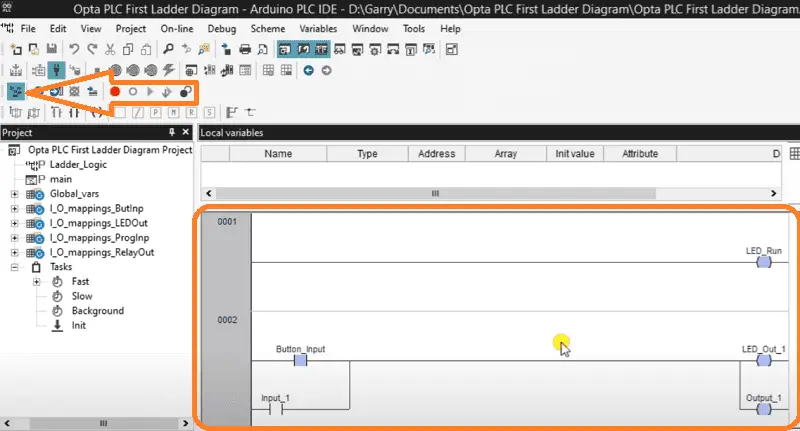
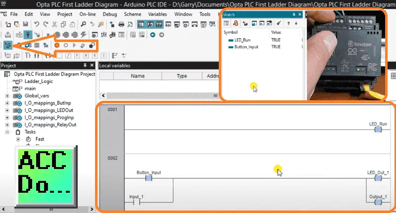
Select the live debug mode icon on the main menu.
This will highlight the inputs and outputs as the program operates. The visualization is a good way to ensure your program works correctly.
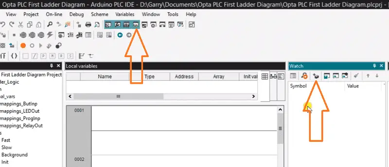
Select the watch icon on the main menu. This will display the watch window.
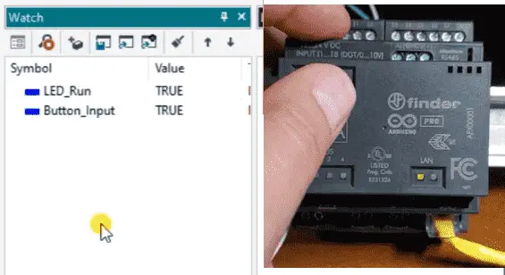
We can enter and select the variables (tags) we want to monitor.
Watch the video below to see how to create ladder diagrams with the Arduino Opta IoT PLC.
Arduino Opta PLC – IoT and Industry 4.0 Enabler
Arduino Opto IoT PLC Series
Opta – Frequently Asked Questions (FAQ)
Finder OPTA 8A Series – Tutorials
Datasheet
Quickstart Sheet
Arduino Opta Hardware
Arduino PLC IDE
Arduino Software Download Page
(Arduino IDE, PLC IDE, PLC IDE Tools)
Watch on YouTube: Arduino OPTA PLC IDE – Ladder Diagram First Program
If you have any questions or need further information, please contact me.
Thank you,
Garry
If you’re like most of my readers, you’re committed to learning about technology. Numbering systems used in PLCs are not challenging to learn and understand. We will walk through the numbering systems used in PLCs. This includes Bits, decimals, Hexadecimal, ASCII, and Floating points.
To get this free article, subscribe to my free email newsletter.
Use the information to inform other people how numbering systems work. Sign up now.

The ‘Robust Data Logging for Free’ eBook is also available for free download. The link is included when you subscribe to ACC Automation.