The Machine Simulator (MS) is part of the EasyPLC software suite. It has many built-in machines, like the palletizing machine, that show different programming techniques. The palletizing conveyor example is one of these machines, and we will use the Do-More Designer PLC programming software. This will demonstrate a sequencer example. In this case, a box is placed upon a skid. The logic will step through various steps to perform the task. A counter will control these steps. This is one of the easiest fundamental ways all PLCs can be programmed for a sequence.
We will use the free Do-More Designer programming software and PLC simulator to program this EasyPLC palletizing machine simulator palletizing conveyor. This will be done using Modbus TCP (Ethernet) for communications. The program sequencer allows for quick and easy control of the automation system. Using the five steps for program development, we will show how this sequencer is programmed. Let’s get started.
Learn PLC programming the easy way. See below how to receive a 10% discount on this cost-effective learning tool. Invest in yourself today.
Previously we have done the following:
Easy PLC Installing the Software – Video
EasyPLC Software Suite – Quick Start – Video
Click PLC – Easy Transfer Line Programming – Video
Productivity PLC Simulator – Chain Conveyor MS – Video
Do-More PLC – EasyPLC Box Selection Program – Video
Click PLC EasyPLC Gantry Simulator – Video
Click PLC Simple Conveyor EasyPLC – Video
EasyPLC Paint Line Bit Shift – BRX Do-More PLC – Video
Click PLC – EasyPLC PLC Mixer Programming – Video
Click PLC EasyPLC Warehouse Stacker Example – Video
– Operation Video
EasyPLC Machine Simulator Productivity PLC Robotic Cell – Video
EasyPLC Simulator Robotic Cell Click PLC – Video
Define the task: (Step 1 – Do-More Easyplc Palletizing Conveyor)
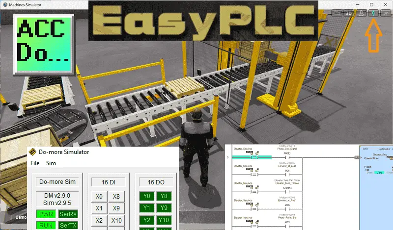
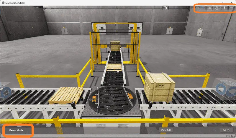
The first step of Do-More or any PLC program development is determining what must be done. Start the EasyPLC Machine Simulator (MS). Select the start button on the main page or select machines from the main menu at the machines simulator window.
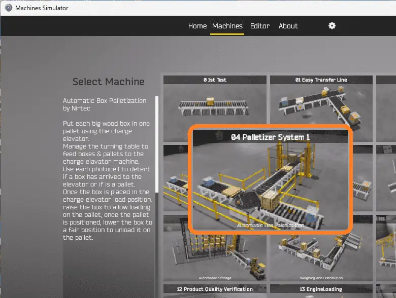
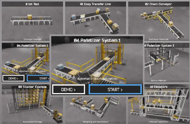
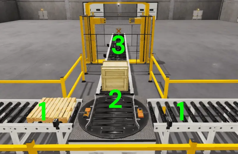
All the available machines will now be displayed. Click on the “04 Palletizer System 1”. This is the example we will be programming. To the left of the screen, information will be displayed on how the palletizing machine needs to function.
Use the charge elevator to move each large wooden box onto a pallet. Utilize the tuning table to direct the boxes and pallets to the elevator palletizing machine. The photocells will detect the arrival of boxes and pallets. Once the box is in the elevator, raise it to the loading position for pallet placement. After positioning the pallet, lower the box to unload it safely.
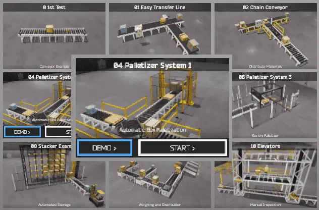
The palletizing machine simulator has a demo mode for this built-in machine. This will allow you to watch the operation of the palletizing conveyor. Select the demo mode for the palletizer system 1.
The demo mode will show you the basics of the palletizing conveyor operation.
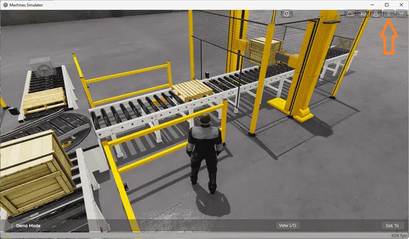
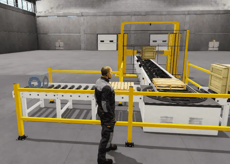
Move around the 3D virtual environment. The icons on the top of the window allow you to move around this 3D environment. The first icon is the default selection. This will enable you to move around without bumping into the components. The last icon will automatically show you around this virtual environment. The first-person mode will mimic a person in your 3D learning world. The third person will show you an operator and their relationship to the palletizing machine. Once we understand what must be done, we can move on to the next step in developing the Do-More PLC program.
Define the Inputs and Outputs: (Step 2 – Do-More Easyplc Palletizing Conveyor)
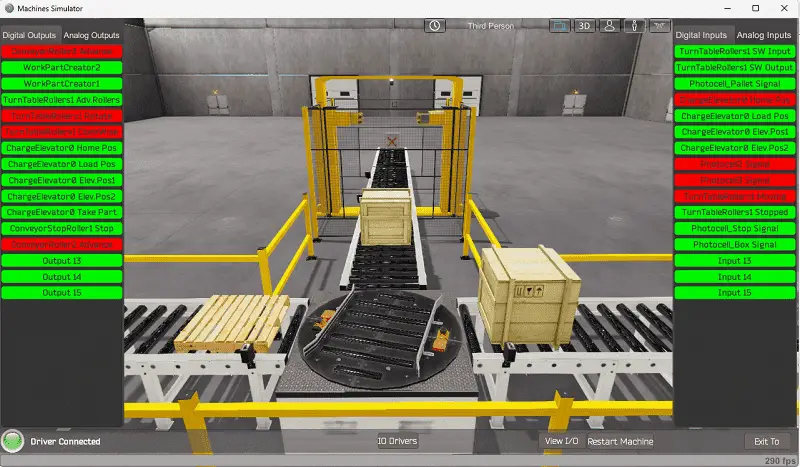
At the bottom of the machine simulator window, the View IO will display the inputs and outputs required for this palletizer conveyor example. While still in demo mode, you can see the operation of the inputs and outputs.
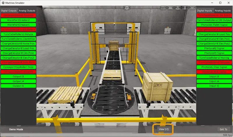
The EasyPLC Palletizer Sample 1 will require 13 digital outputs and 13 digital inputs.
If you are unsure what output or input is doing, start the palletizer conveyor machine in Start mode.
Select the View IO on the bottom middle of the palletizing machine simulator window. You can manually run the palletizer without any control or Do-More PLC simulator connection.
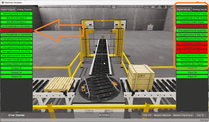
Clicking on the outputs will allow you to turn them on manually. You can then monitor the inputs to see their operation. The restart button on the bottom of the machine simulator window will reset the scene back to the start.
The following table will define the inputs and outputs (IO) and Modbus addresses in the Do-More PLC we will use for this program.
| Digital Type | Description | Do-More PLC Modbus Address | Machine Simulator Modbus Address |
| PLC Output – MS Input | Conveyor Roller 3 Advance | MI1 – 10001 | 0 |
| PLC Output – MS Input | Work Part Creator 2 Pallet | MI2 – 10002 | 1 |
| PLC Output – MS Input | Work Part Creator 1 Box | MI3 – 10003 | 2 |
| PLC Output – MS Input | Turn Table Rollers Advance | MI4 – 10004 | 3 |
| PLC Output – MS Input | Turn Table Rotate | MI5 – 10005 | 4 |
| PLC Output – MS Input | Turn Table Clockwise | MI6 – 10006 | 5 |
| PLC Output – MS Input | Charge Elevator Home | MI7 – 10007 | 6 |
| PLC Output – MS Input | Charge Elevator Load | MI8 – 10008 | 7 |
| PLC Output – MS Input | Charge Elevator Position 1 | MI9 – 10009 | 8 |
| PLC Output – MS Input | Charge Elevator Position 2 | MI10 – 10010 | 9 |
| PLC Output – MS Input | Charge Elevator Take Part | MI11 – 10011 | 10 |
| PLC Output – MS Input | Conveyor Stop Roller | MI12 – 10012 | 11 |
| PLC Output – MS Input | Conveyor Roller 2 Advance | MI13 – 10013 | 12 |
| PLC Input – MS Output | Turn Table SW Input | MC1 – 1 | 0 |
| PLC Input – MS Output | Turn Table SW Output | MC2 – 2 | 1 |
| PLC Input – MS Output | Photocell Pallet Signal | MC3 – 3 | 2 |
| PLC Input – MS Output | Charge Elevator Position Home | MC4 – 4 | 3 |
| PLC Input – MS Output | Charge Elevator Position Load | MC5 – 5 | 4 |
| PLC Input – MS Output | Charge Elevator Position 1 | MC6 – 6 | 5 |
| PLC Input – MS Output | Charge Elevator Position 2 | MC7 – 7 | 6 |
| PLC Input – MS Output | Photocell 2 Signal | MC8 – 8 | 7 |
| PLC Input – MS Output | Photocell 3 Signal | MC9 – 9 | 8 |
| PLC Input – MS Output | Turn Table Moving | MC10 – 10 | 9 |
| PLC Input – MS Output | Turn Table Stopped | MC11 – 11 | 10 |
| PLC Input – MS Output | Photocell Stop Signal | MC12 – 12 | 11 |
| PLC Input – MS Output | Photocell Box Signal | MC13 – 13 | 12 |
Note: The machine simulator will be offset by one on the Modbus Addresses.
See the video below for the demo mode and determining inputs and outputs.
Develop a logical sequence of operation: (Step 3 – Do-More Easyplc Palletizing Conveyor)
A flow chart or sequence table is used to understand the process that must be controlled thoroughly. It must also answer questions like the following:
What happens when electrical power and/or pneumatic air is lost? What happens when the input/output devices fail? Do we need redundancy?
This step is where you will spend most of your time. Understanding everything about the operation will save you time. It will help prevent you from continuously re-writing the PLC program logic. Knowing all these answers upfront is vital in developing the PLC program.
Our Do-More PLC palletizing conveyor example will break down into three parts: the conveyors controlling the box and skid, the turntable, and the elevator.
The box and skid creation will happen if the end sensor does not see the item. This will ensure that a box and skid are always at the end of the conveyor, ready for the turn table.
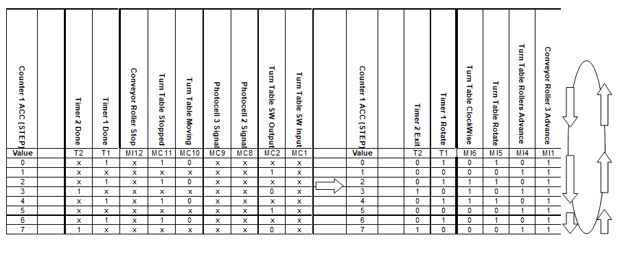
Our sequence table for the turn table will show the input signals on the left side and the output signals on the right. The value of the counter is shown with each step.
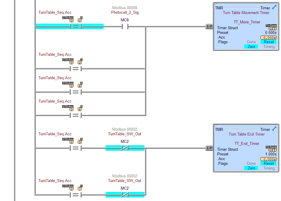
We can move to the next step by looking at the counter value of 0 and if we have timer 1 done and the turn table stopped signal. The output that activates at a counter value of 0 is timer one, and the turn table rotates. Repeat the process for all the other counter values until the last one of 7. This will reset the counter back to 0.
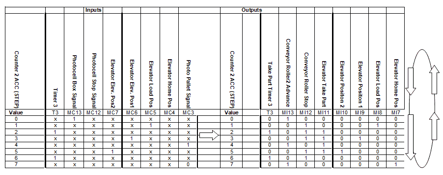
Counter 2 controls the sequence for the elevator. Once again, the input signals are on the left side, and the output signals are on the right. The value of the counter is shown with each step.
We can move to the next step if the counter value is 0 and we have the box signal. The conveyor roller two advance is the output that activates at a counter value of 0. Repeat the process for all the other counter values until the last one of 7. This will reset the counter back to o.
A PLC programmer must know how everything about the sequence and operation of the machine before programming.
Ask questions or view existing documentation to ensure you know the logical steps to the machine’s operation.
Develop the Do-More PLC program: (Step 4 – Do-More Easyplc Palletizing Conveyor)
The next step in our program development will be writing the ladder logic code for the Do-More PLC simulator example. We will use the Do-More Designer programming software with the Do-More PLC simulator.
The BRX Do-More Series will install the program, communicate the controller instructions, and address the controller.
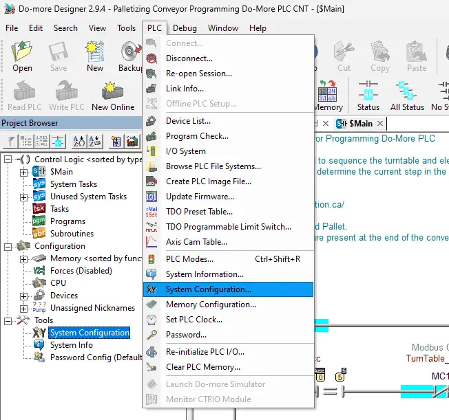
Select the system configuration using the configure icon on the main menu. You can also call this up by selecting it under tools in the project browser window. The third way to get to the system configuration is by using the main menu | PLC | System configuration…
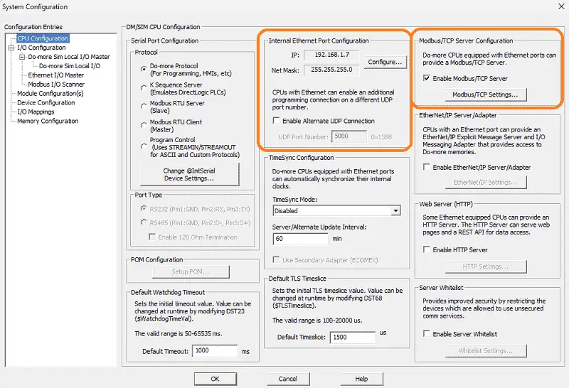
The Do-More PLC simulator will use the same IP address as the computer running the software. This address can be seen under the heading Internal Ethernet Port Configuration. Ensure that the Enable Modbus / TCP Server is selected. Click the Modbus / TCP Settings… button. Select OK to return to the system configuration window.
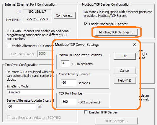
We will leave the default port of 502 for our Modbus communication.
Our Do-More PLC is now a Modbus TCP Server to the EasyPLC Modbus TCP Client. Note the IP address we are using for the Do-More PLC simulator. This will be used later to connect to the EasyPLC machine simulator.
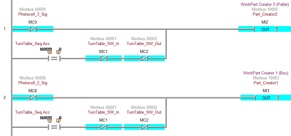
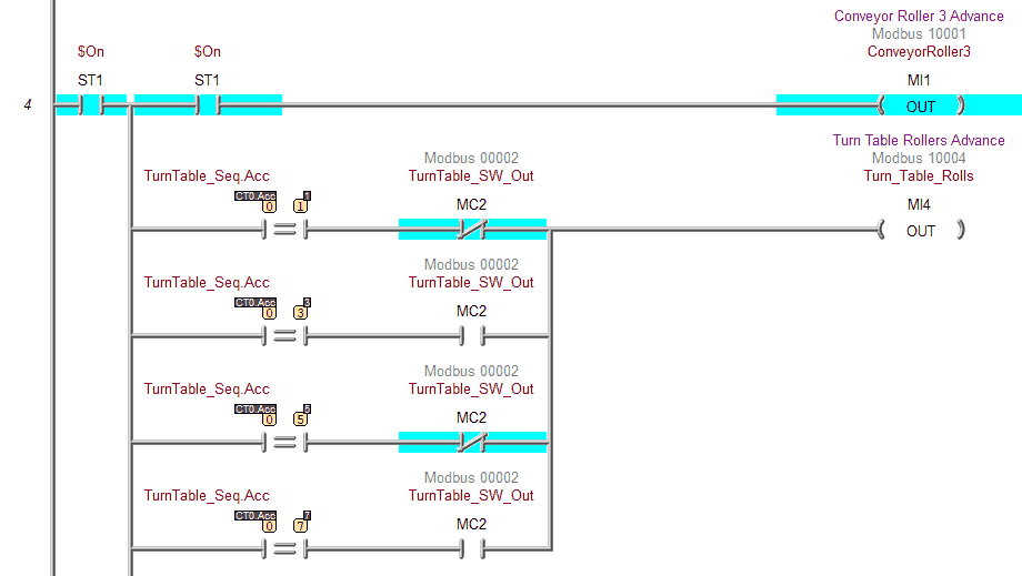
The first two rungs of ladder logic will control the box and pallet conveyors. The conveyor will activate when the photocell for each component is not seen. This will automatically produce a part. When the turn table needs the part, this is compared to the sequence for the step, and the conveyors will also advance.
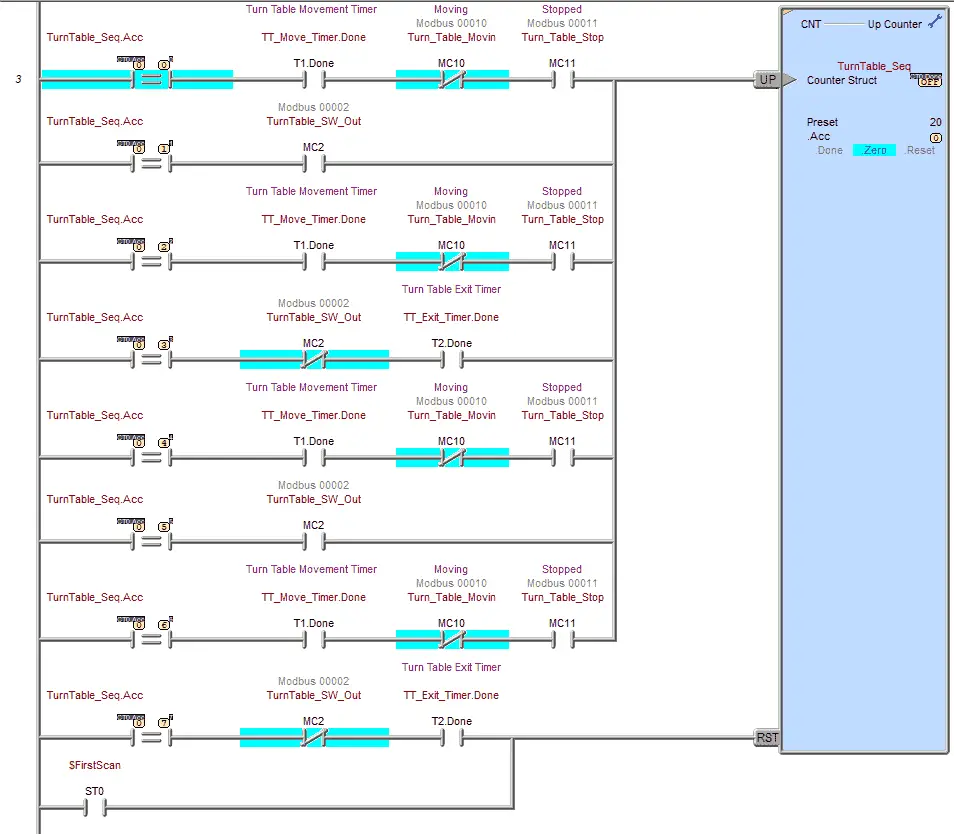
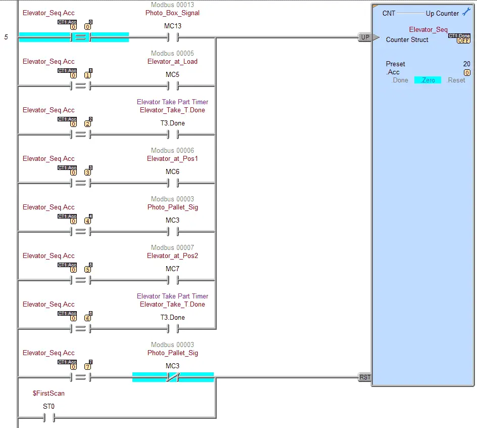
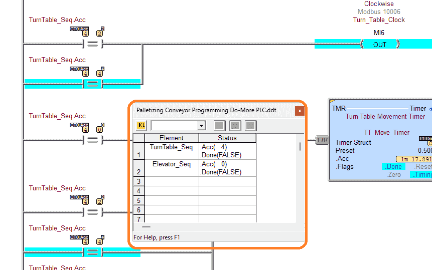
This is counter 1, which controls the turn table sequence. Returning to the sequence table, you can see the steps and inputs that will advance (increment) the counter.
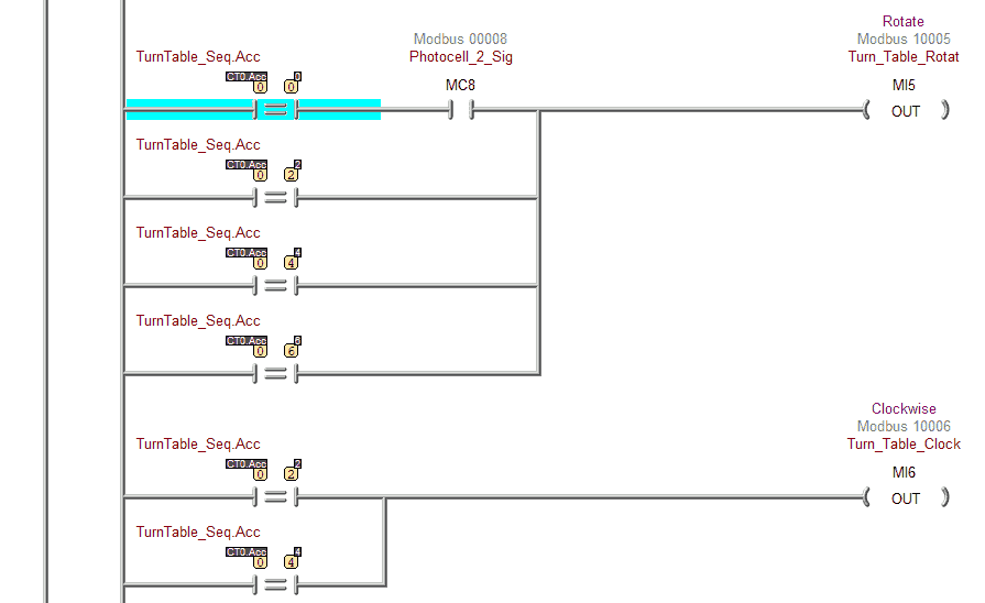
Here are the outputs of the sequencer. You will see the counter value and inputs that will activate each output. If the output is to be turned on with more than 1 of the counter values, you can see that the conditions are placed in parallel.
This is counter 2, which controls the elevator sequence. Returning to the sequence table, you can see the steps and inputs that will advance (increment) the counter.
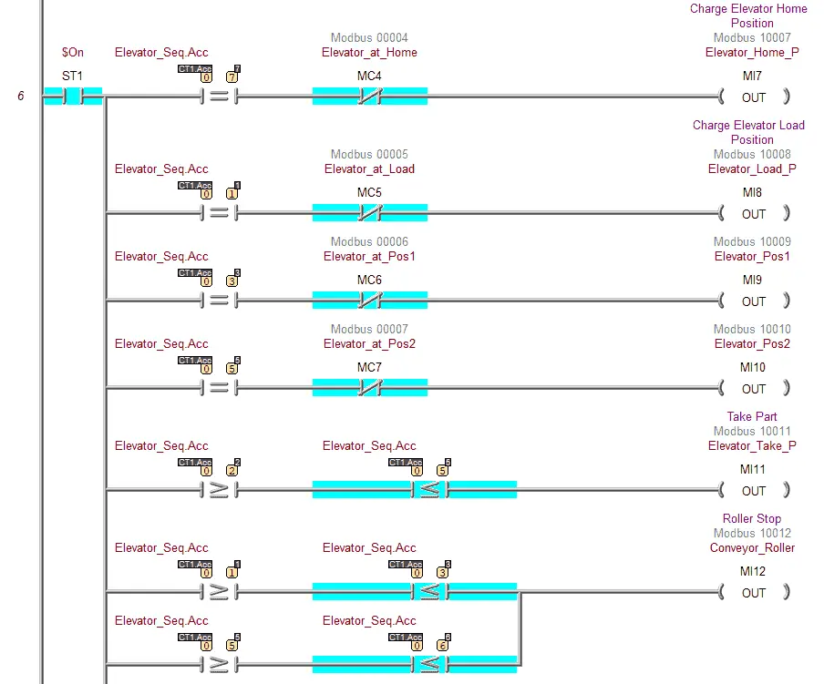
Here are the outputs of the elevator sequencer. You will see the counter value and inputs that will activate each output. If the output is to be turned on with more than 1 of the counter values, you can see that the conditions are placed in parallel.
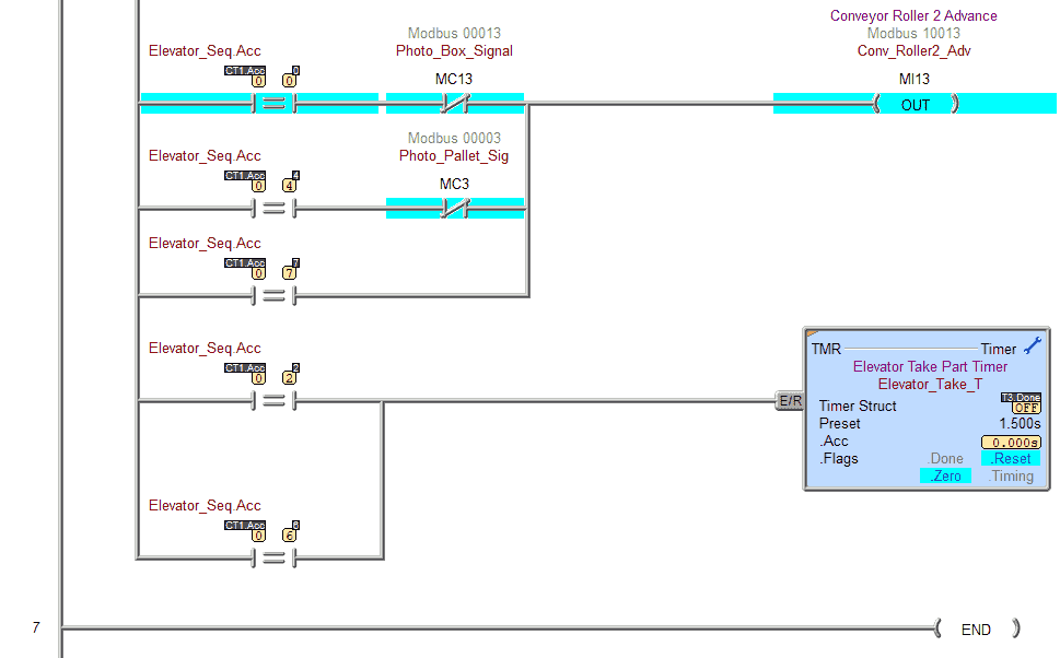
This is the end of the ladder logic code. Download the Do-More program to the Do-More PLC simulator. Ensure that the simulator is in run mode.
Watch the video below to see this Do-More PLC program in action
Test the program: (Step 5 – Do-More Easyplc Palletizing Conveyor)
We will use Modbus TCP on our Do-More PLC simulator to communicate with the EasyPLC Machine Simulator.
Call up the palletizing conveyor machine simulator in start mode.
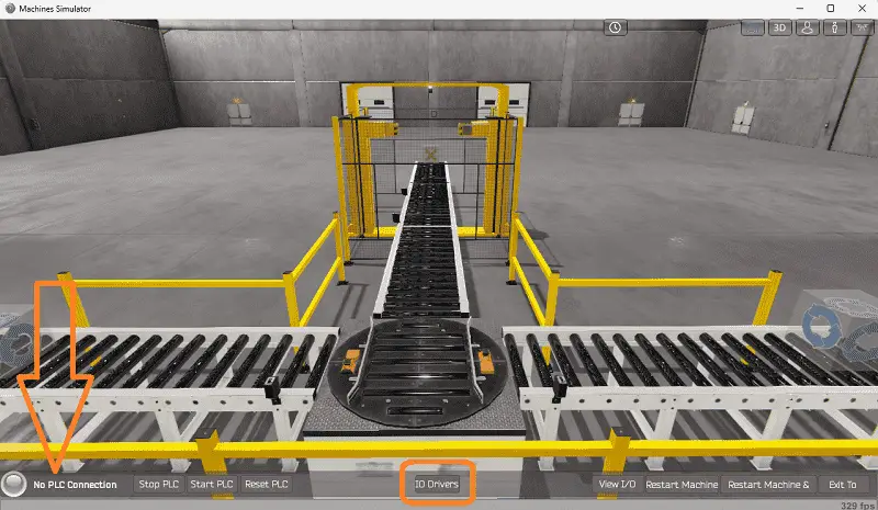
The status of the machine simulator will be at the bottom of the screen. Currently, we have no PLC connected. Select IO Drivers on the bottom middle of the screen.
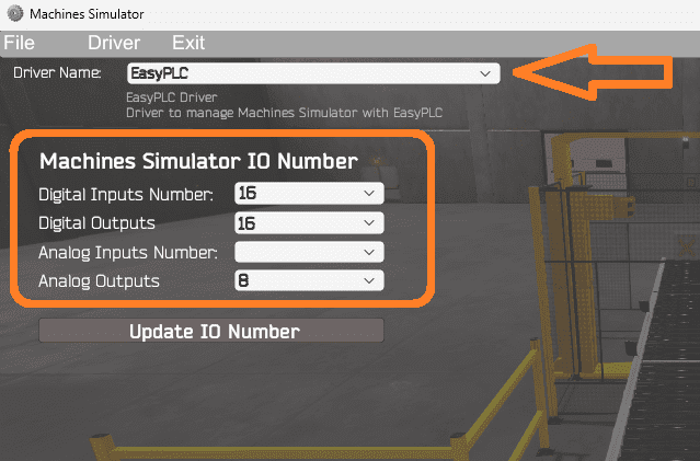
The machine simulator IO number will be displayed. Ensure we select more IO than the number required for our palletizing machine.
The EasyPLC driver is selected by default.
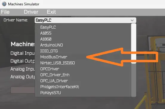
Under the driver pull-down menu, select “ModBusDriver.” This driver will communicate Modbus TCP (Ethernet) and Modbus RTU (Serial). Select the down arrow on the driver’s name.
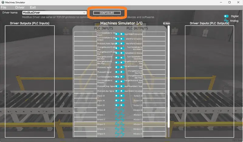
Select the configure button.
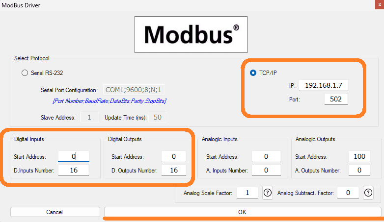
We can now enter the information for our Modbus driver. Select TCP/IP. This means the Ethernet port on the computer will communicate with the Do-More PLC simulator.
The digital inputs from MS to the Do-More PLC will be MC1 to MC17. This will start at address 0 due to the offset of 1. Digital outputs from MS to the Do-More PLC will be MI1 to MI17. This will begin at address 0 due to the offset of 1. Select the OK button.
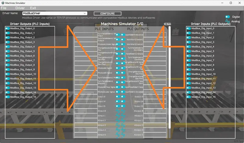
You will now see the inputs and outputs specified for the Modbus driver. We can now manually assign the driver outputs to the PLC inputs and driver inputs to the PLC outputs. However, the automatic assignment works well and will save you time.
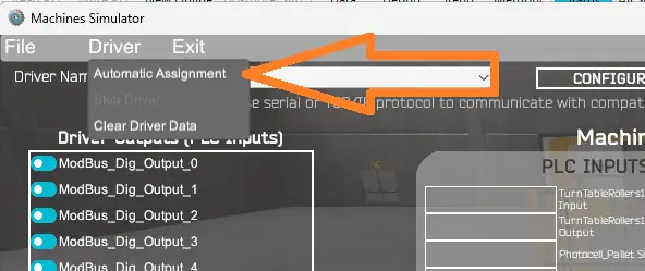
Select Automatic Assignment from the driver option in the main menu.
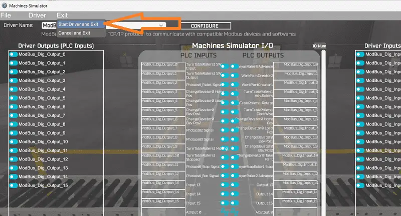
This will automatically assign the PLC IO to the Machine Simulator IO. Select start driver and exit from the main menu.
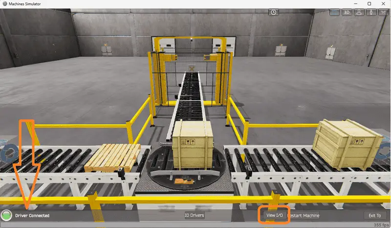
On the bottom left side of the window, the driver communicates to the Do-More PLC simulator with the green light. Select view IO to know the input and output status of the machine simulator.
Ensure that the Do-More PLC simulator is in run mode. We can see the operation of our palletizing machine. The digital inputs and outputs of the MS will correspond to the PLC controller.
Using the Data View window of the Do-More Designer programming software, we can also watch the inputs and output operations.
Using Machine Simulator (MS) to test the program will ensure that our program works. Troubleshooting is quickly done without damage to any physical hardware.
You can practice your modification and debug by modifying the palletizing operation in the following way:
– Add a control panel with start and stop buttons.
– Add a jog button to the control panel to sequence through the steps.
– Calculate the rate of full pallets coming out of the palletizer machine in pallets per hour.
Let me know how you make out in the comments below.
Download the Do-More PLC sample program and sequence table here.
Watch the video below to see the five steps of program development applied to the palletizing machine. The machine simulator is one of the best applications to help you learn PLC programming.
EasyPLC Software Suite is a complete PLC, HMI, and Machine Simulator Software package. This PLC learning package includes the following:
Easy PLC – PLC Simulation allows programming in Ladder, Grafcet, Logic Blocks, or Script.
HMI System – Easily create a visual human-machine interface (HMI)
Machine Simulator – A virtual 3D world with real-time graphics and physical properties. PLC programs can be tested using EasyPLC or through other interfaces. (Modbus RTU, TCP, etc.)
Machine Simulator Lite – Designed to run on Android Devices.
Machine Simulator VR – Virtual Reality comes to life so you can test, train or practice your PLC programming.
Purchase your copy of this learning package for less than USD 75 for a single computer install or less than USD 100 to allow different computers.
Receive 10% off the price by typing in ACC in the comment section when you order. http://www.nirtec.com/index.php/purchase-price/
Learn PLC programming the easy way. Invest in yourself today.
Watch on YouTube: EasyPLC Simulator Robotic Cell BRX Do-More PLC
If you have any questions or need further information, don’t hesitate to contact me.
Thank you,
Garry
If you’re like most of my readers, you’re committed to learning about technology. Numbering systems used in PLCs are not challenging to learn and understand. We will walk through the numbering systems used in PLCs. This includes Bits, Decimals, Hexadecimal, ASCII, and Floating Points.
To get this free article, subscribe to my free email newsletter.
Use the information to inform other people how numbering systems work. Sign up now.

The ‘Robust Data Logging for Free’ eBook is also available for free download. The link is included when you subscribe to ACC Automation.