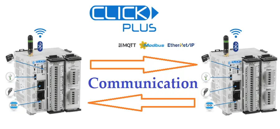
We will connect two Click PLUS PLCs and communicate in three different ways. Using the send and receive commands, we will set up one PLC to be the master (client) and communicate with the slave (server). WiFi, Ethernet, and Serial communication will share common memory areas between the Click PLCs.
 The send and receive commands have been covered before in our Click PLC Series, but we will look further at the timing of the communication. Detecting and correcting communication errors will be discussed and implemented. We will also create a heartbeat for the remote Click slave (server) PLC. This will allow the remote controller to determine if communications have stopped with the Click master (client). Wiring a pushbutton and some ladder logic code will allow us to time the throughput of each of the communication methods. Let’s get started.
Our entire Click series can be found here. All the previous information for the Click PLC can be applied to the Click PLUS.
Previously we looked at the following:
Software Installation – Video
Click Software Establish Communication – Video
MQTT Communication – Video
Data Logging – Video
Click Plus Real-Time Clock – Video
Serial Communication Timing – Video
Retentive Data Memory Registers – Video
Click PLC Analog Input Non-Linear Scaling – Video
How to Connect Pushbutton Switch to PLC – Video
The programming software and manuals can be downloaded from the Automation Direct website free of charge.
Watch the video below to see the wiring, programming, and testing of our lighted pushbutton switch to the Click PLC.
What is PLC to PLC Communication?
PLC-to-PLC communication means that two central processing units (CPUs) can communicate and share information. This is done asynchronously with the PLC scan. This means the PLC scan will not wait until the communication is finished. Data is then transferred when the transmission has been completed. This is not predictable.
 If you require synchronous communication between the PLCs, then it is better to hardwire physical inputs and outputs between the controllers. This way, the update times on the IO are predictable.
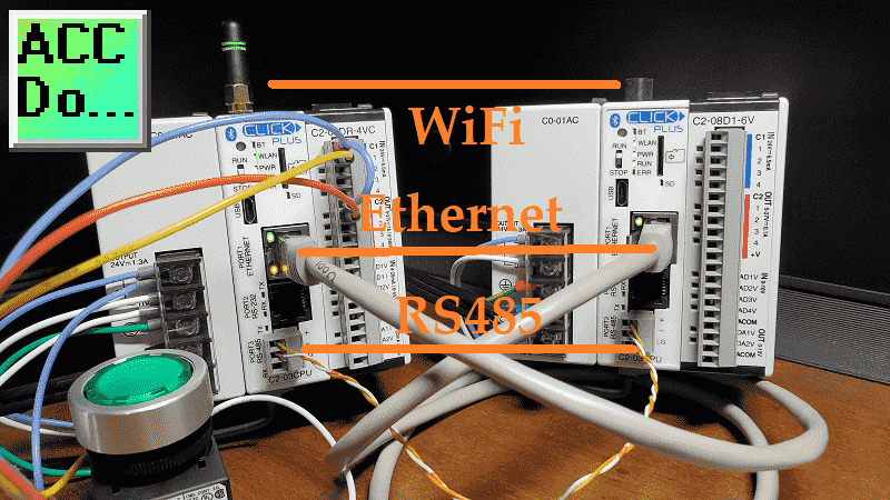
The physical media or wiring between the Click PLCs can be accomplished in several ways. In our examples, we will look at three different media. WiFi will use an antenna on the PLC to communicate through the air to a wireless router. The router will then direct the traffic to the destination. The maximum distance will depend on the mounting and obstacles between the controllers. Typically, this is about 45 meters or about 150 feet.
Ethernet communication comes in a CAT5 or CAT6 type of wire. This can be directly plugged in from the RJ45 connector on one PLC to the RJ45 connector on the other. The maximum distance is 90 meters or about 325 feet. Routers or switches may be used to connect multiple ethernet devices. RS485 serial communication uses a shielded twisted pair wire. This inexpensive way to create a local network can have multiple communication drops. The maximum specified cable length is 1200 meters or about 4000 feet.
The protocol is the information that is being sent through the media. We will use the Modbus protocol in the above three media types. This is a client/server or master/slave type of communication. The client will start all communications. Servers will respond to the communication from the client only. RS485 is serial communication and will use Modbus RTU protocol. Other serial media include RS232 and RS422. There can only be one master to multiple slaves using Modbus RTU. WiFi and Ethernet will use Modbus TCP protocol. Using this protocol, you can have numerous masters to multiple slaves. Addressing is done with an IP address.
Errors that happen within the Modbus protocol are called exception responses. The error codes that may be seen when using Modbus with the Click PLC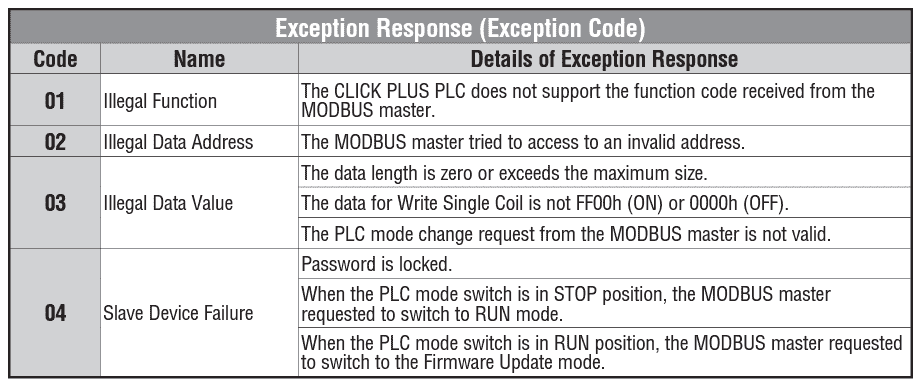 Other protocols standard with WiFi and Ethernet are MQTT and Ethernet IP. The Click PLC can communicate with both protocols, but Modbus is the easiest method of PLC to PLC Click Communication.
Click to Click Remote IO Hardware
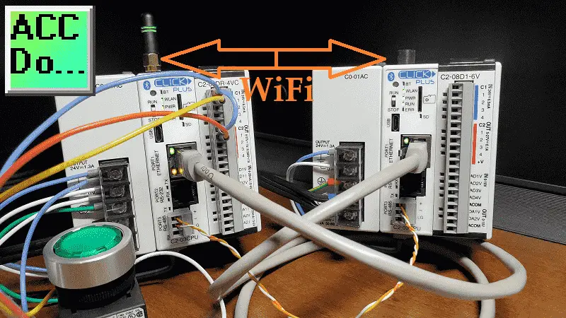
We are using two Click PLUS PLCs for our communication. The Click PLUS is the latest edition of the Click family of controllers. It can communicate wirelessly through WiFi. If you do not wish to communicate this way, then any of the other Click CPUs will be able to communicate with each other. Just ensure that the desired port type is specified when ordering the PLC.
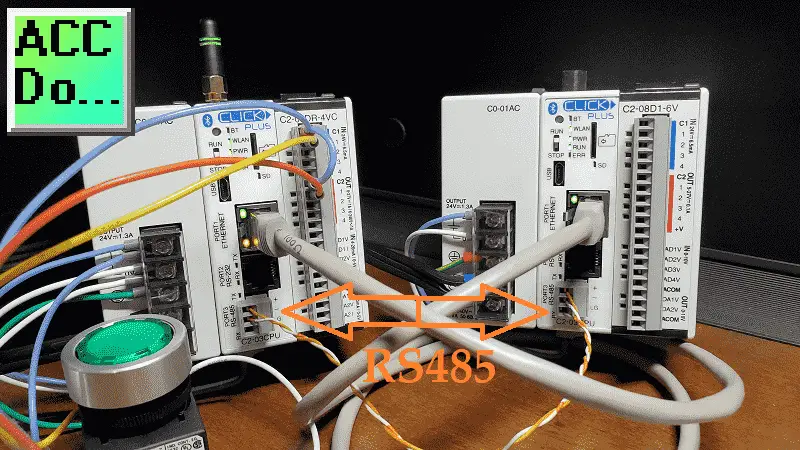
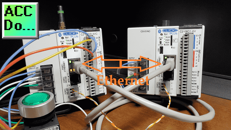
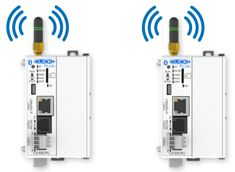 Our hardware consists of two Click PLUS CPUs, part number C2-03CPU. The client PLC will have a C2-08DR-4VC card slot, and the server PLC will have a C2-08D1-6V card slot. A pushbutton is wired into the first input of the client PLC.
Two wires connect port 3 of each Click PLC. This is the RS485 port. The + terminals and the – terminals are connected. A CAT5 cable is connected between each Ethernet RJ45 Port 1 of the CPU controllers.
 Antennas can be added to each of the controllers. Since this is set up on my desk, the WiFi signal to the router can be seen without using an antenna.
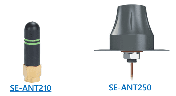 The antennas are ordered separately. I would recommend the SE-ANT250. This will mount on the outside of the panel.
See the video below to view the hardware and antenna options.
Click Send and Receive Command Timing
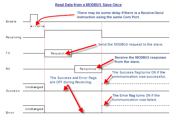
The send and receive commands must be executed one at a time through any of the ports. Timing of the commands is critical to ensure that protocol messages are written and read.
The send command will have three flags that can be used in the ladder logic program to control the Modbus commands.
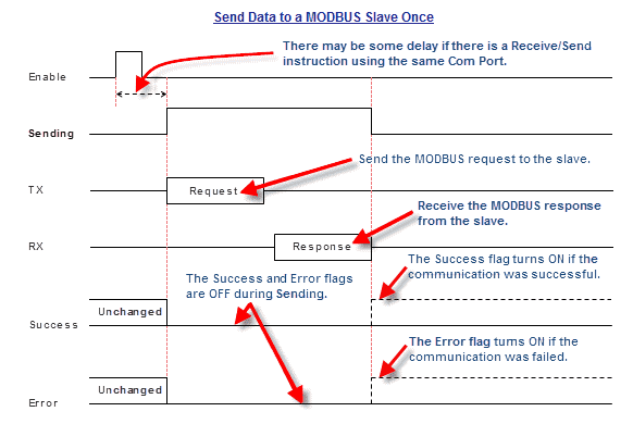 Sending Bit will be on when the protocol request and response are taking place.
Success Flag will turn on if communication is successful.
Error Flag would turn on if communication failed.
The receive command will also have three flags we will use in the ladder logic program to control the Modbus commands.
 Sending Bit will be on when the protocol request and response are taking place.
Success Flag will turn on if communication is successful.
Error Flag would turn on if communication failed.
Looking at part of the programming example for the RS485 send and receive example, we can see that the not sending and leading-edge bits of the success and error will send the next command.
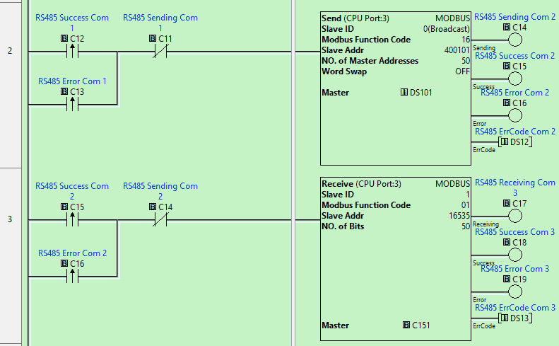 Cascading the send and receive commands in the Click will ensure that your timing is done quickly and efficiently.
A heartbeat in the program will monitor the connection between two or more controllers, so the remote controller(s) will know if communication has been lost. Since Modbus is a master/slave type of setup, the slave will not know when communication has been lost unless we use some code. The master controller will pulse a bit every second using the system’s bit of the Click. The slave controller will monitor the leading edge of this pulse bit. If it does not see this Bit for two seconds, the remote PLC will know that communication has stopped. We will look at this logic in our three examples.
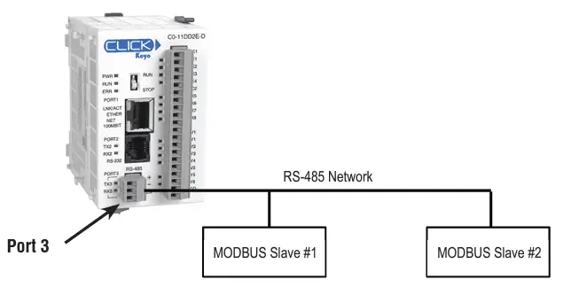
Click to Click RS485 Modbus RTU Communication
The RS485 Modbus RTU connection is a two-wire twisted pair. The communication parameters must be the same for the master and all the slave units. In Modbus Serial communication like Modbus RTU, the controller sending the commands is called the master. The slave is the controller that will respond to the commands from the master. In Modbus TCP (Ethernet), the master is referred to as the client, and the slave is the server.
 We can start the Click PLC programming software twice and connect to the master and the slave PLCs. Using the main menu, select Setup | Com Port…
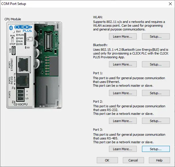
Select Port 3. This is the RS485 port on the Click CPU.
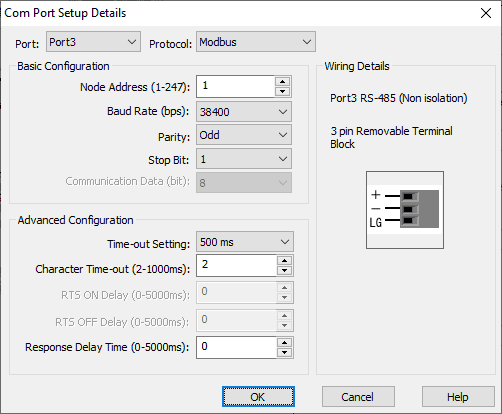
Modbus protocol is the default for this port selection. The baud rate, parity, and stop-bit communication parameters must match the master and the slave PLC settings. We are using the highest baud rate setting on the Click PLC. Typically, the longer the physical cable runs, the slower you need to set the baud rate. You may have to experiment with this rate depending on your environment and cable length. Node address, in our case, will be left at the default of 1 for both controllers. The master Click PLC does not have to have a node address because it is the only one initiating the communication. If we had multiple slave controllers, then each slave would have to have a unique number. This way, the master Click PLC would know which slave Click PLC to send or request information.
Our Click PLC network ports are now set up.
As mentioned, all communications are initiated from the master PLC using the Modbus protocol. We will now look at the ladder logic program for the Click Master RTU PLC.
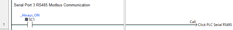
Our main ladder logic program will call a subroutine called Click PLC Serial RS485. This subroutine will handle all the communications between the Click controllers.
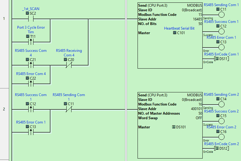
The first two lines of the controller will use the send instructions to write information into the slave unit. You will see that the slave ID is set to 0. This unique mode will broadcast the message to all Modbus RTU slaves on the network. Since we have only one slave, we could have also used the value of 1 that was set above as the node address. Double-clicking on the send instruction, we can look at more details.
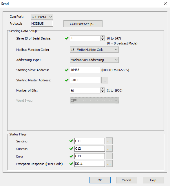
The Modbus function code is set for 15. This is used to write multiple coils. Our addressing type is selected for Modbus 984 Addressing, and the starting slave address is 16485. The starting master address is C101. Call up the address picker from the main menu | Program.
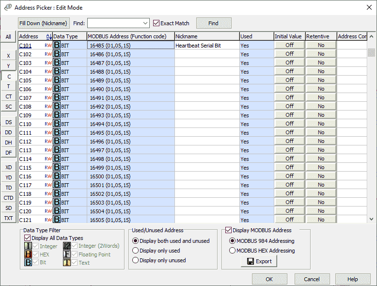
Select “Display Modbus Address” in the bottom right-hand side of the address picker window. This will display the Modbus addresses of all of the memory locations in the Click PLC. 16485 is the address for C101.
Looking back at the send instruction, we are sending 50 bits. This means that bits C101 to C150 from the master PLC are being sent to bits C101 to C150 of the slave PLC.
Status flags are then set for the send instruction. We will use these for the timing of the communication. The first scan flag is used on the first rung to send the first 50 bits. The output flags on the first send instruction will trigger the second send instruction.
Our next send instruction will use the write multiple registers. The starting slave address will be 400101, DS101 in the Click PLC. We will write 50 registers. Registers DS101 to DS150 from the master PLC will be written to DS101 to DS150 of the slave PLC.
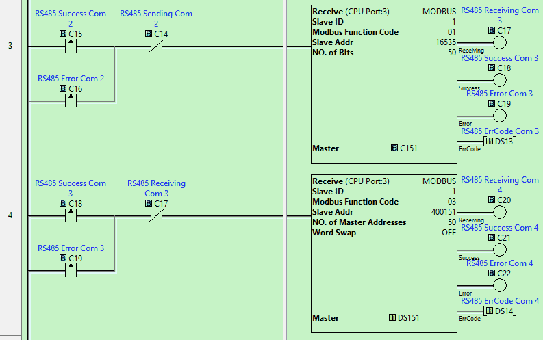
The flags from the second send instruction will now trigger the receive instruction. The receive instruction function code will read coil status. We will read 50 bits starting at 16535 (Address C151) of the slave PLC and write them into the master starting at C151. The output flags of this received instruction will trigger the next received instruction.
We have two send and 2 receive instructions that will now pass 100 bits and words between the two Click PLCs. We will read 50 registers starting at 400151 (Address DS151) of the slave PLC and write them in the master starting at DS151. The output flags of this instruction will then trigger the first send instruction again.
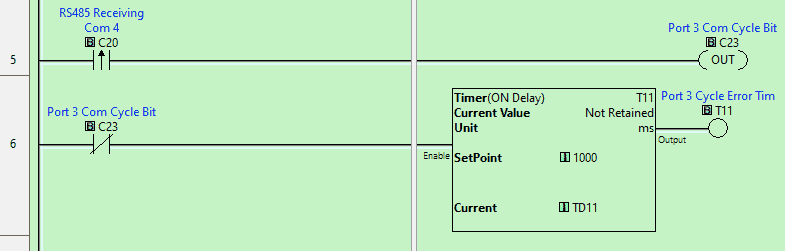
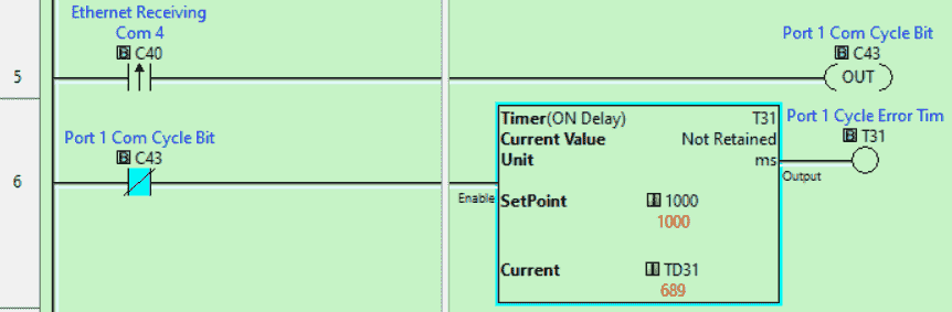
The sending and receiving instructions cycle uses the flag bits. If this cycle stops, we will need to start cycling again. The leading edge of the last received instruction triggers an internal bit. The normally closed of this Bit will then start a timer set for 1000 milliseconds (1 second). The leading edge of this timer bit will then start the first scan instruction again in parallel to the first scan instruction. We can now ensure that the information will continue to be updated.
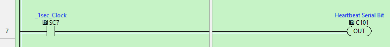
A heartbeat is sent to the first Bit we write to the Click slave PLC. This is used to tell the slave if communication is still active. Even though we are cycling above with our commands, it may not mean that information is being sent. There could be errors on the line, and slave plc will need to know this and react.
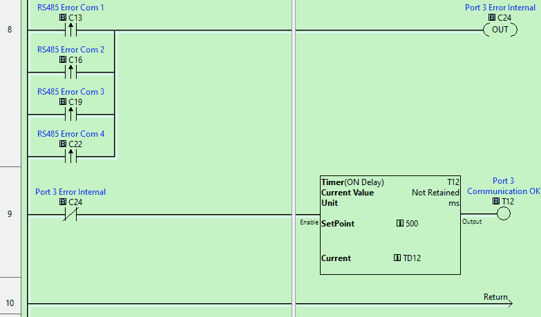
The Click master PLC will also need to know if the information is valid. We are looking at the leading edge of each of the RS485 Error communication bits. This will trigger an internal bit. The normally closed of this Bit will then turn on a timer. The timer is set for 500 milliseconds. If the timer done Bit is on, then communications are OK. We can use this in other areas of our Program.
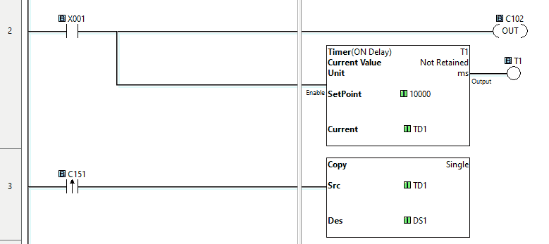
When input X001 from our pushbutton switch is on, this will turn on Bit C102 and start a timer. Returning to the main ladder logic of our Click master PLC, we will implement some code to determine the throughput of our communications. Our remote Click slave will have the following code.

This will read C102 and then set C151. When bit C151 is read from the Click master PLC, the value in the timer is then copied to DS1. DS1 will then contain the throughput value in milliseconds.
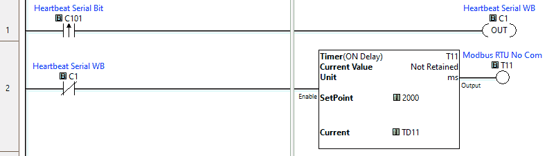
The Click slave PLC does not need any code for communication to the master other than a heartbeat to ensure the transmission is valid. This is an asynchronous communication from the master. The heartbeat pulse comes from the master bit C101. Using the leading edge of this Bit to turn on an internal bit, we use this normally closed internal Bit as the condition for a timer. If the timer times out and the timer done Bit comes on, we know communications have been lost.
Call up the Data View under monitor in the program tab of the navigation window on both the master and slave PLC Click controllers.
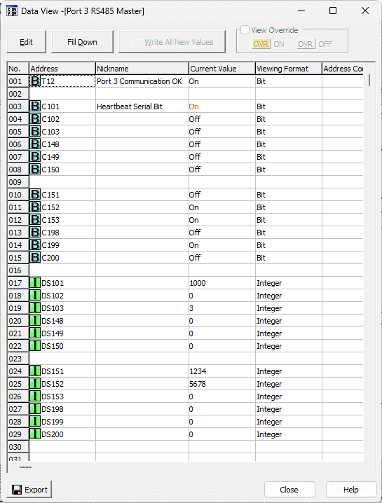 The master will write the first block of bits. You can see the heartbeat bit pulsing. The slave will write the next block of bits so the master can read. The following two blocks contain registers—one for the master to write and one for the slave to write.
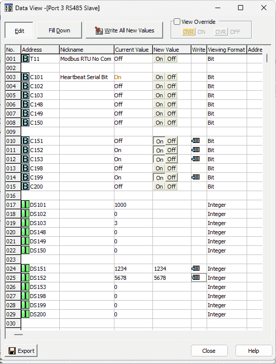 Changing the bit or word status in one controller will reflect in the other.
Download the program and documentation from the link below.
Watch the video below to see this in operation.
Click to Click Ethernet Modbus TCP Communication
The Ethernet Modbus TCP connection is a CAT5 or CAT6 cable with RJ45 connectors. A static IP address must be set for the client and all the servers. In Modbus Ethernet communication like Modbus TCP, the controller sending the commands is called the client. The server is the controller that will respond to the commands from the client. In Modbus RTU (Serial), the client is referred to as the master, and the server is the slave. An easy way to remember this is the two ‘S’s are server/slave.
We can start the Click PLC programming software twice and connect to the client and the server PLCs. Using the main menu, select Setup | Com Port…
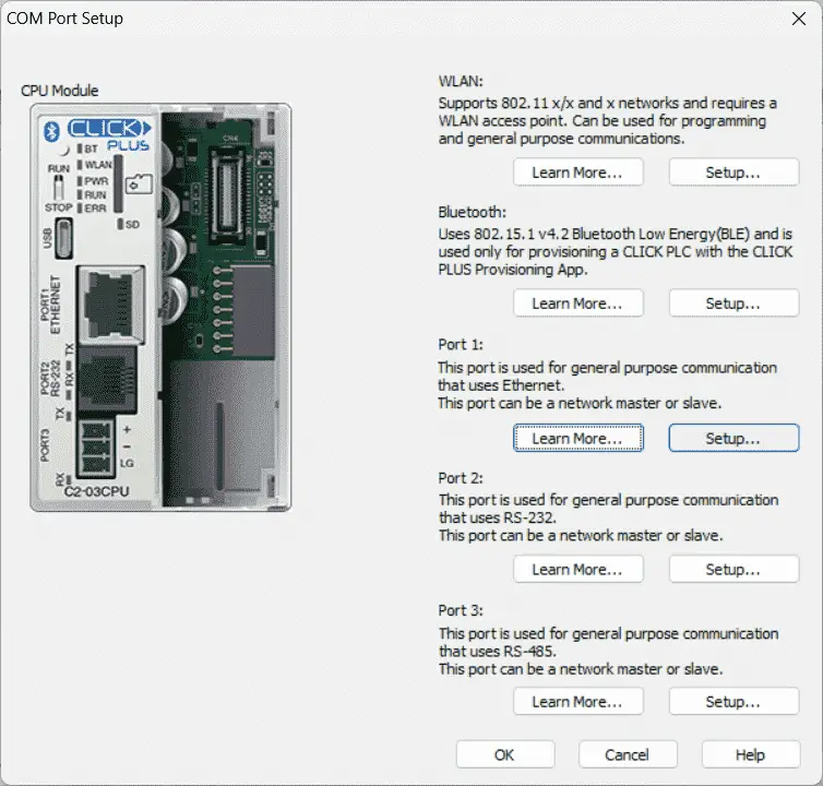
Select Port 1. This is the Ethernet RJ45 port on the Click CPU.
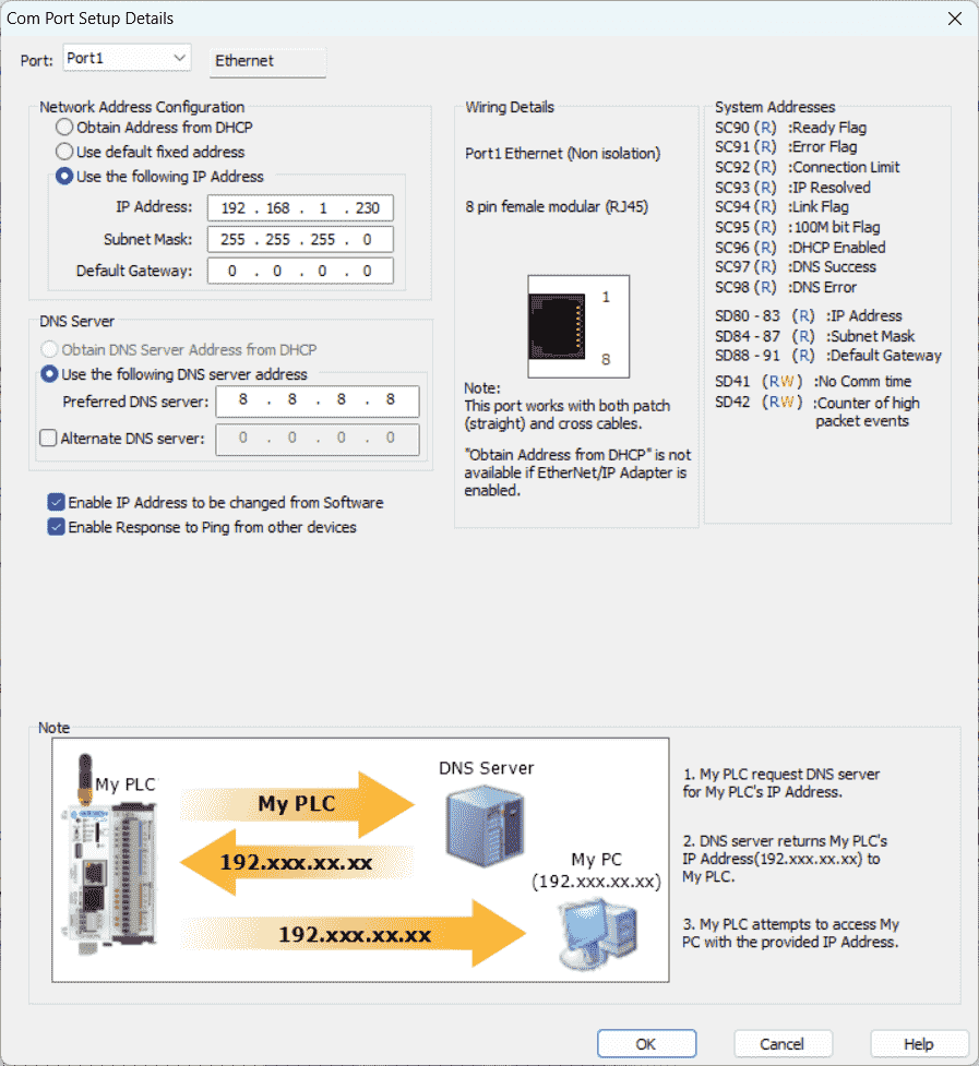
This is where we will set up the static IP address of the port on the client and the server. This IP address is used to determine where the message will be directed. TCP/IP refers to the Transmission Control Protocol and Internet Protocol, which provides the transmission medium for Modbus TCP messaging. This is the worldwide standard for the world wide web (WWW). The primary function of TCP is to ensure that all packets of data are received correctly, while IP ensures that messages are correctly addressed and routed. TCP/IP is the transport protocol and does not determine what the data means or how the data is to be interpreted. Modbus TCP protocol will be the data, and each Click PLC will analyze this information. This is how the Ethernet will transfer information between the two Click PLCs.
The client Click PLC will use the address 192.168.1.230, and the server Click PLC will use the address 192.168.1.231.
Select OK to return to the port selection and then hit OK again to return to the main screen.
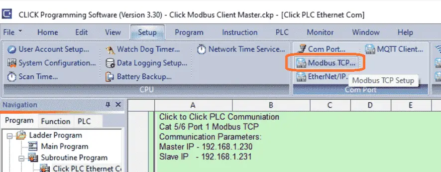 Under the Com port… selection in the setup menu, select Modbus TCP…
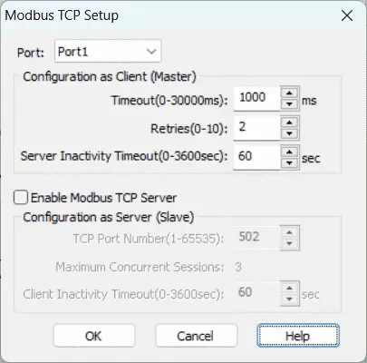 This Modbus TCP Setup window will allow us to set parameters around the protocol.
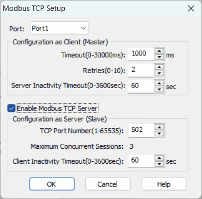 Enable the Modbus TCP Server on the Click Remote IO PLC.
Our Click PLC network ports are now set up.
As mentioned, all communications are initiated from the client PLC using the Modbus protocol. We will now look at the ladder logic program for the Click PLC Client Master.
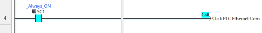
Our main ladder logic program will call a subroutine called Click PLC Ethernet Com. This subroutine will handle all the communications between the Click controllers.
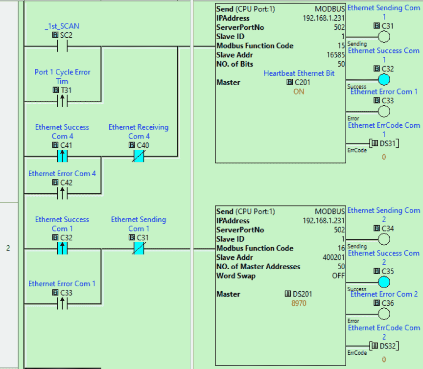
The first two lines of the controller will use the send instructions to write information into the server unit. You will see that the IP is set to 192.168.1.231. This unique address will ensure the message gets to the network server. Double-clicking on the send instruction, we can look at more details.
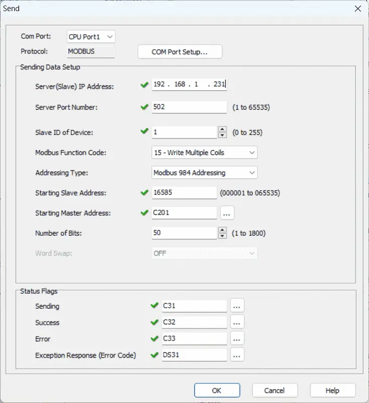
The Modbus function code is set for 15. This is used to write multiple coils. Our addressing type is selected for Modbus 984 Addressing, and the starting slave address is 16585. The starting client address is C201. Call up the address picker from the main menu | Program.
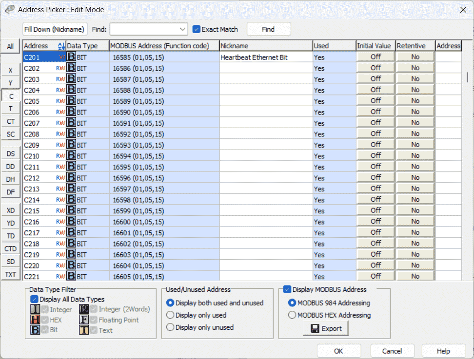
Select “Display Modbus Address” in the bottom right-hand side of the address picker window. This will display the Modbus addresses of all of the memory locations in the Click PLC. 16585 is the address for C201.
Looking back at the send instruction, we are sending 50 bits. This means that bits C201 to C250 from the client PLC are being sent to bits C201 to C250 of the server PLC.
Status flags are then set for the send instruction. We will use these for the timing of the communication. The first scan flag is used on the first rung to send the first 50 bits. The output flags on the first send instruction will trigger the second send instruction.
Our next send instruction will use the write multiple registers. The starting slave address will be 400201, DS201 in the Click PLC. We will write 50 registers. Registers DS201 to DS250 from the client PLC will be written to DS201 to DS250 of the server PLC.
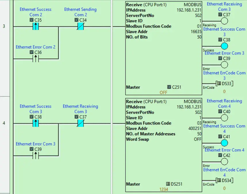
The flags from the second send instruction will now trigger the receive instruction. The receive instruction function code will read coil status. We will read 50 bits starting at 16635 (Address C251) of the server PLC and write them into the client starting at C251. The output flags of this received instruction will trigger the next received instruction.
We have two send and 2 receive instructions that will now pass 100 bits and words between the two Click PLCs. We will read 50 registers starting at 400251 (Address DS251) of the server PLC and write them in the client starting at DS251. The output flags of this instruction will then trigger the first send instruction again.
The sending and receiving instructions cycle uses the flag bits. If this cycle stops, we will need to start cycling again. The leading edge of the last received instruction triggers an internal bit. The normally closed of this Bit will then start a timer set for 1000 milliseconds (1 second). The leading edge of this timer bit will then start the first scan instruction again in parallel to the first scan instruction. We can now ensure that the information will continue to be updated.

A heartbeat is sent to the first Bit we write to the Click server PLC. This is used to tell the server if communication is still active. Even though we are cycling above with our commands, it may not mean that information is being sent. There could be errors on the line, and server plc will need to know this and react.
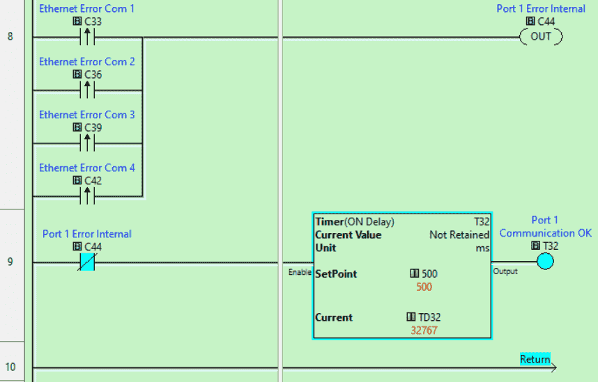
The Click client PLC will also need to know if the information is valid. We are looking at the leading edge of each of the Ethernet Error communication bits. This will trigger an internal bit. The normally closed of this Bit will then turn on a timer. The timer is set for 500 milliseconds. If the timer done Bit is on, then communications are OK. We can use this in other areas of our program.
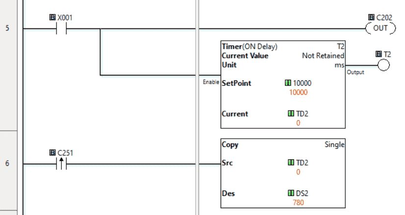
Returning to the main ladder logic of our Click client PLC, we will implement some code to determine the throughput of our communications. When input X001 from our pushbutton switch is on, this will turn on Bit C202 and start a timer. Our remote Click server will have the following code.

This will read C202 and then set C251. When bit C251 is read from the Click client PLC, the value in the timer is then copied to DS2. DS2 will then contain the throughput value in milliseconds.
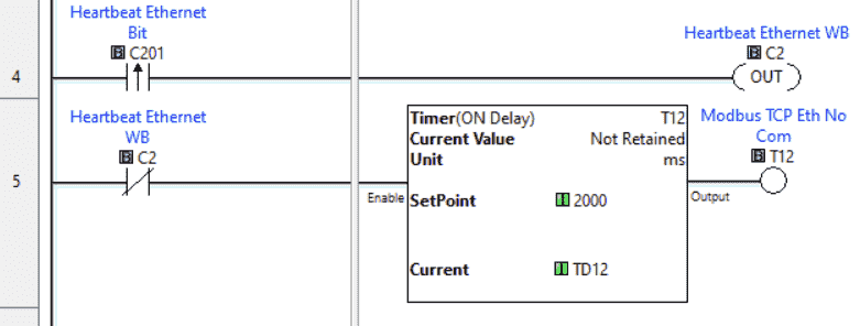
The Click server PLC does not need any code for communication to the client other than a heartbeat to ensure the transmission is valid. This is asynchronous communication from the client. The heartbeat pulse comes from the client bit C201. Using the leading edge of this Bit to turn on an internal bit, we use this normally closed internal Bit as the condition for a timer. If the timer times out and the timer done Bit comes on, we know communications have been lost.
Call up the Data View under monitor in the program tab of the navigation window on both the client and server PLC Click controllers.
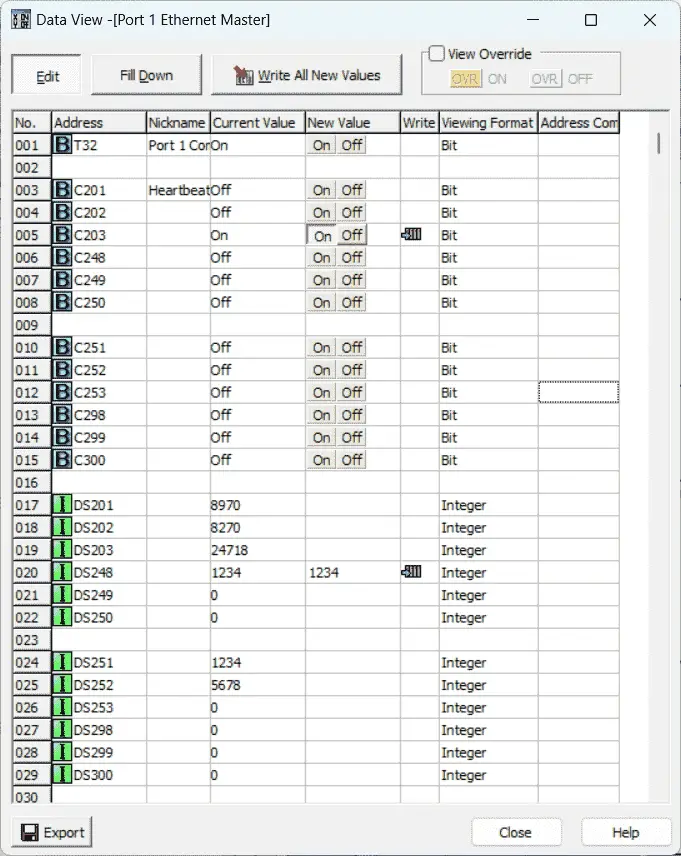 You can see the heartbeat bit pulsing. The client will write the first block of bits. The server will write the next block of bits so the client can read. The following two blocks contain registers—one for the client to write and one for the server to write.
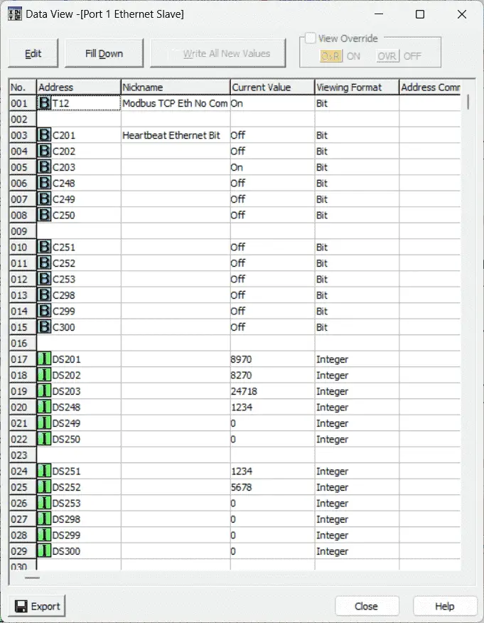 Changing the bit or word status in one controller will reflect in the other.
Download the program and documentation from the link below.
Watch the video below to see this in operation.
Click to Click WiFi Modbus TCP Communication
The Click WiFi connection is wireless. A static IP address must be set for the client and all the servers. The controller sending the commands in Modbus TCP communication is called the client. The server is the controller that will respond to the commands from the client. In Modbus RTU (Serial), the client is referred to as the master, and the server is the slave. An easy way to remember this is the two ‘S’s are server/slave.
We can start the Click PLC programming software twice and connect to the client and the server PLCs. Using the main menu, select Setup | Wireless Port…
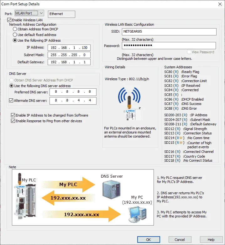
Connection to the wireless LAN basic configuration for SSID and Password can be entered. This is the name of the wireless network and the password to connect. See the Click Plus Establish Communication post for more details on connecting WiFi and provisioning through Bluetooth.
A static IP address must be set for the client and the server’s WLAN (Wireless LAN) port. This IP address determines where the message will be directed using Ethernet. TCP/IP refers to the Transmission Control Protocol and Internet Protocol, which provides the transmission medium for Modbus TCP messaging. The primary function of TCP is to ensure that all packets of data are received correctly, while IP ensures that messages are correctly addressed and routed. TCP/IP is the transport protocol and does not determine what the data means or how the data is to be interpreted. Modbus TCP protocol will be the data, and each Click PLC will analyze this information. This is how WiFi will transfer information between the two Click PLCs.
The client Click PLC will use the address 192.168.1.130, and the server Click PLC will use the address 192.168.1.131.
Select OK to return to the main screen.
Under the Wireless port… selection in the setup menu, select Modbus TCP…
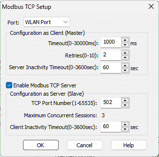 This Modbus TCP Setup window will allow us to set parameters around the protocol. We will leave the default settings for both the client and server. Click PLCs. Ensure that the “Enable the Modbus TCP Server” on the Click Remote IO PLC is selected.
Our Click PLC network ports are now set up.
As mentioned, all communications are initiated from the client PLC using the Modbus protocol. We will now look at the ladder logic program for the Click PLC Client Master.

Our main ladder logic program will call a subroutine called Click PLC WiFi Com. This subroutine will handle all the communications between the Click controllers.
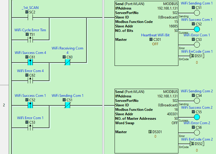
The first two lines of the controller will use the send instructions to write information into the server unit. You will see that the IP is set to 192.168.1.131. This unique address will ensure the message gets to the network server. Double-clicking on the send instruction, we can look at more details.
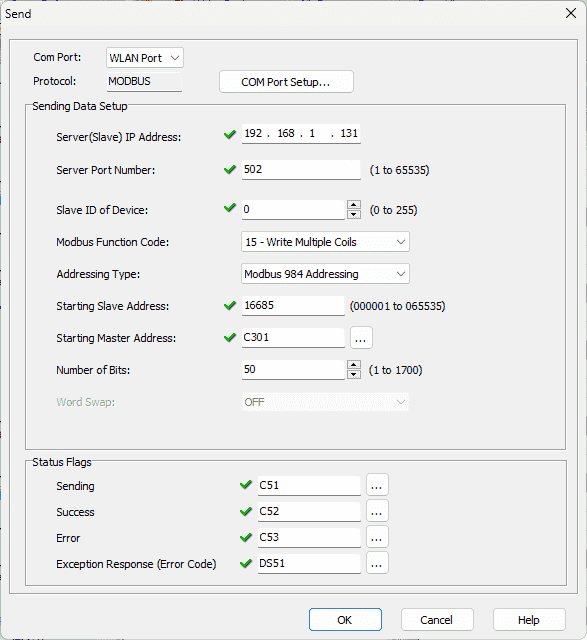
The Modbus function code is set for 15. This is used to write multiple coils. Our addressing type is selected for Modbus 984 Addressing, and the starting slave address is 16685. The starting client address is C301. Call up the address picker from the main menu | Program.

Select “Display Modbus Address” in the bottom right-hand side of the address picker window. This will display the Modbus addresses of all the memory locations in the Click PLC. 16685 is the address for C301.
Looking back at the send instruction, we are sending 50 bits. This means that bits C301 to C350 from the client PLC are being sent to bits C301 to C350 of the server PLC.
Status flags are then set for the send instruction. We will use these for the timing of the communication. The first scan flag is used on the first rung to send the first 50 bits. The output flags on the first send instruction will trigger the second send instruction.
Our next send instruction will use the write multiple registers. The starting slave address will be 400301, DS301 in the Click PLC. We will write 50 registers. Registers DS301 to DS350 from the client PLC will be written to DS301 to DS350 of the server PLC.
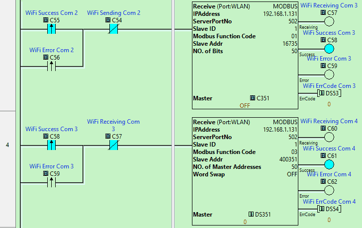
The flags from the second send instruction will now trigger the receive instruction. The receive instruction function code will read coil status. We will read 50 bits starting at 16735 (Address C351) of the server PLC and write them into the client starting at C351. The output flags of this received instruction will trigger the next received instruction.
We have two send and 2 receive instructions that will now pass 100 bits and words between the two Click PLCs. We will read 50 registers starting at 400351 (Address DS351) of the server PLC and write them in the client starting at DS351. The output flags of this instruction will then trigger the first send instruction again.
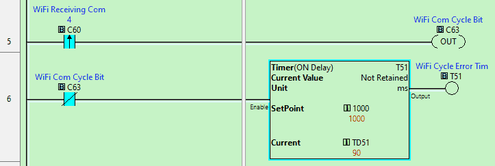
The sending and receiving instructions cycle uses the flag bits. If this cycle stops, we will need to start cycling again. The leading edge of the last received instruction triggers an internal bit. The normally closed of this Bit will then start a timer set for 1000 milliseconds (1 second). The leading edge of this timer bit will then start the first scan instruction again in parallel to the first scan instruction. We can now ensure that the information will continue to be updated.
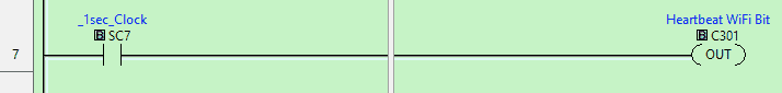
A heartbeat is sent to the first Bit we write to the Click server PLC. This is used to tell the server if communication is still active. Even though we are cycling above with our commands, it may not mean that information is being sent. There could be errors on the line, and server plc will need to know this and react.
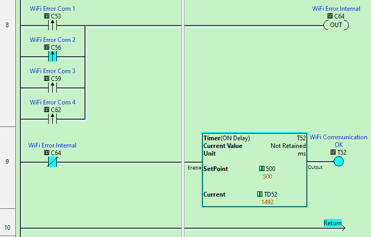
The Click client PLC will also need to know if the information is valid. We are looking at the leading edge of each of the Ethernet Error communication bits. This will trigger an internal bit. The normally closed of this Bit will then turn on a timer. The timer is set for 500 milliseconds. If the timer done Bit is on, then communications are OK. We can use this in other areas of our program.
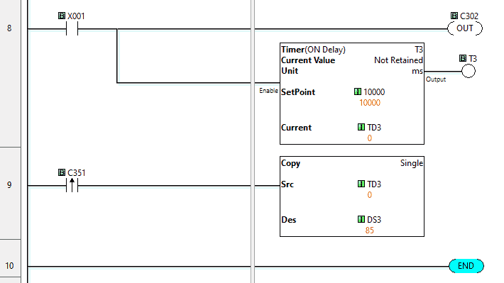
Returning to the main ladder logic of our Click client PLC, we will implement some code to determine the throughput of our communications. When input X001 from our pushbutton switch is on, this will turn on Bit C302 and start a timer. Our remote Click server will have the following code.
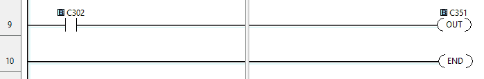
This will read C302 and then set C351. When bit C351 is read from the Click client PLC, the value in the timer is then copied to DS3. DS3 will then contain the throughput value in milliseconds.
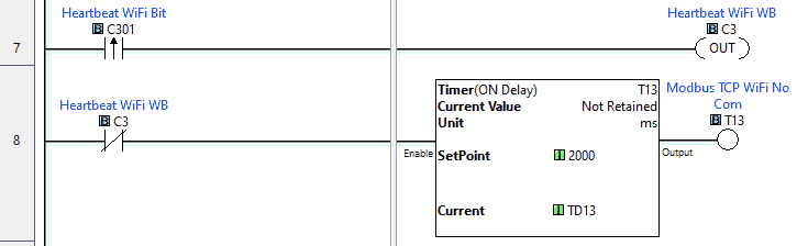
The Click server PLC does not need any code for communication to the client other than a heartbeat to ensure the transmission is valid. This is asynchronous communication from the client. The heartbeat pulse comes from the client bit C301. Using the leading edge of this Bit to turn on an internal bit, we use this normally closed internal Bit as the condition for a timer. If the timer times out and the timer done Bit comes on, we know communications have been lost.
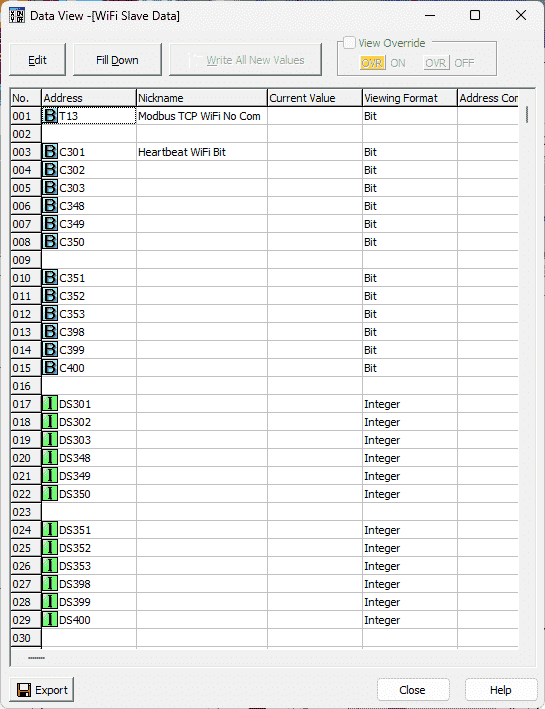
Call up the Data View under monitor in the program tab of the navigation window on both the client and server PLC Click controllers.
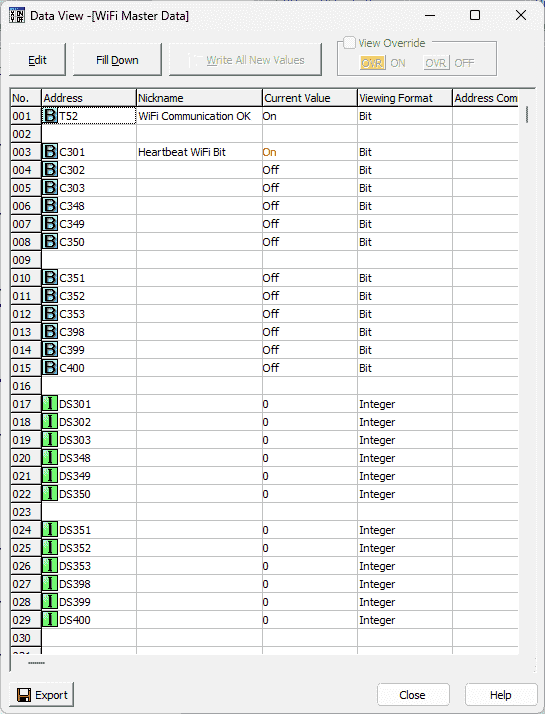 You can see the heartbeat bit pulsing. The client will write the first block of bits. The server will write the next block of bits so the client can read. The following two blocks contain registers—one for the client to write and one for the server to write.
 Changing the bit or word status in one controller will reflect in the other.
Watch the video below to see the operation of our program in the Click PLUS PLCs.
Download the Click PLC program here.
Purchase your ferrule kit here with this associated link:
Video on this ferrule kit.
Click PLC Support Links
The Click PLC can be programmed using free Click programming software from Automation Direct. Here is a link to the software.
Version 3.31
Version 2.60
The entire Click PLC series can be found here. This includes the Click PLUS release.
All previous posts and information are still valid with the Click PLC line-up.
YouTube Click Playlist
YouTube Click PLUS Playlist
Click and Click PLUS PLC Overview
Click and Click PLUS PLC Videos from Automation Direct
Modbus Learning Links:
Simply Modbus Frequently Asked Questions
Modbus TCP/IP Overview – Real-Time Automation
All You Need to Know About Modbus RTU – Video
Watch the full video on YouTube: Click to Click PLC Communication
– RS485 Communication Video
– Ethernet Communication Video
– WiFi Wireless Communication Video
If you have any questions or need further information, please contact me.
Thank you,
Garry
If you’re like most of my readers, you’re committed to learning about technology. Numbering systems used in PLCs are not challenging to learn and understand. We will walk through the numbering systems used in PLCs. This includes Bits, decimals, Hexadecimal, ASCII, and Floating points. To get this free article, subscribe to my free email newsletter.
Use the information to inform others how numbering systems work. Sign up now. The ‘Robust Data Logging for Free’ eBook is also available as a free download. The link is included when you subscribe to ACC Automation.