We will connect a lighted pushbutton switch to a programmable logic controller (PLC). Using our Click PLUS PLC, we will be assembling, wiring, programming, and testing our pushbutton switch system. The Fuji Electric pushbutton, normally open (NC) contact, will be wired to the first PLC (X1) input. The LED light will connect to the Click PLC (Y1) first output.
 Ferrules will be discussed and demonstrated as a method of wiring any stranded wire. The use of ferrules applies to any automation devices with screw terminals. A ladder logic program will be developed to start and stop this lighted pushbutton light using just a single input. The output LED will turn on if the button is pressed for three seconds. Pressing the button again will turn the light off. This is the safest way of using one input to start and stop output. Let’s get started.
Our entire Click series can be found here. All the previous information for the Click PLC can be applied to the Click PLUS.
Previously we looked at the following:
Software Installation – Video
Click Software Establish Communication – Video
MQTT Communication – Video
Data Logging – Video
Click Plus Real-Time Clock – Video
Serial Communication Timing – Video
Retentive Data Memory Registers – Video
Click PLC Analog Input Non-Linear Scaling – Video
The programming software and manuals can be downloaded from the Automation Direct website free of charge.
Watch the video below to see the wiring, programming, and testing of our lighted pushbutton switch to the Click PLC.
Hardware Components
Here are the components that we will be using.
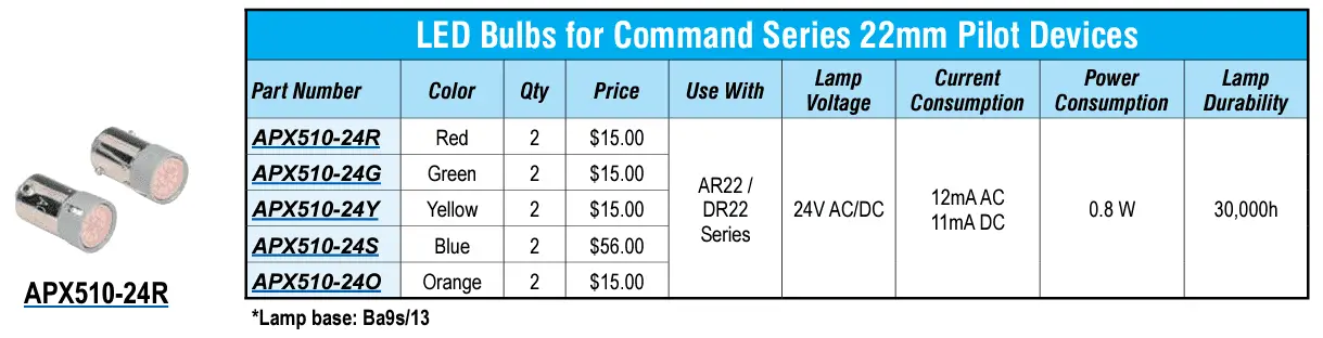
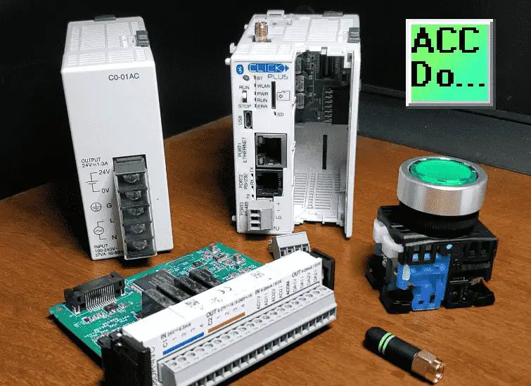 We have a lighted green color pushbutton switch. Pushbuttons are mechanical devices designed to activate an electrical circuit when operated.
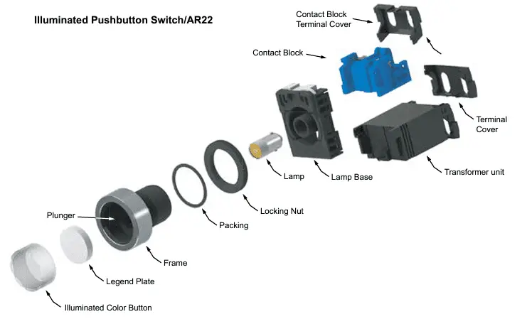 They are available in various colors and operator options, including flush or extended; non-illuminated or illuminated; momentary or maintained action; in 16mm, 22mm, or 30mm mounting dimensions.
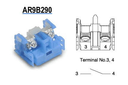
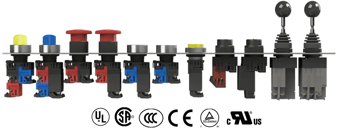 This pushbutton is 22mm illuminated. We have a normally open contact that is blue. Next to it is the transformer for the LED light of the pushbutton.
We then have our CPU unit, which is the Click PLUS PLC. The part number is C2-03CPU.
The PLC 24V DC power supply is part number CO-01AC.
A PLC slot card, part number C2-08DR-4VC will be installed in the CPU unit.
This gives us four inputs, four outputs, and analog inputs and outputs.
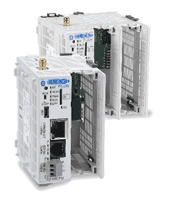 We also have an antenna for the WiFi signal on the PLC CPU.
The antenna will screw into the top of the CPU unit. A panel mount is also available if required.
Tabs on the Click CPU left side will mount into the right side of the power supply. You will see that there is no connector between the two units.
Locking tabs on the top and bottom of the power supply will lock the unit into position.
The connector for the CPU power supply must be wired separately.
This mounts into the bottom of the CPU unit. We will wire from our power supply into the connector at the bottom of the Click PLC 24 Volts.
The slot card can now be mounted into the CPU unit. This will slide into the CPU with the help of some grooves to guide the card to the connector.
Two clips are on the top and bottom of the card to secure it.
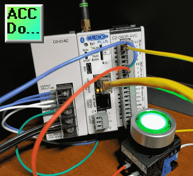
This is our completed assembly for our PLC. We can now connect our lighted pushbutton. Watch the video below to see the assembly of the components.
Wire Gauge Size / Ferrule Connections
Wire gauge size (AWG) refers to its physical diameter size. The larger the gauge size, the smaller the wire, and vice versa. The smaller the gauge size, the larger the wire diameter. Standard wire gauge sizes include 22, 20, 18, 16, 14, 12, and 10.
Determining the maximum current (Amps), the wire will carry is crucial. We will use the “AWG Wire Sizes” table to determine this current. This will determine the maximum amperage we can pass through the gauge size we want to use.
Here is a portion of the table located on Wikipedia:
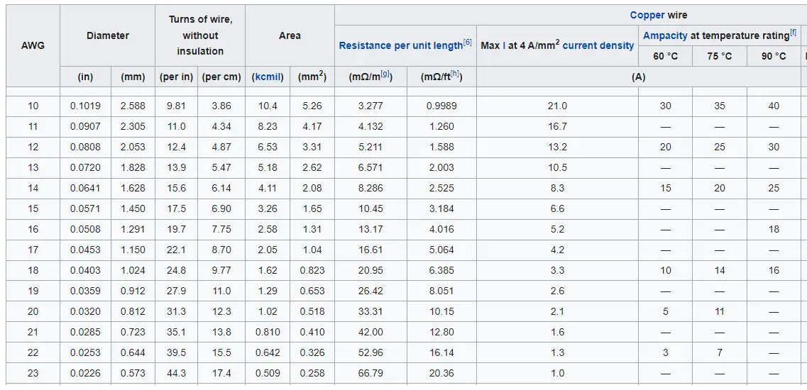 The ampere capacity of the wire is rated at 60 degrees. The National Electrical Code defines this. You will notice that 12 AWG is rated at 20 amps, and 14 SWG is rated at 15 amps. This is the typical size for household wiring and fusing.
We will be using a 20-gauge wire for wiring our lighted pushbutton to the Click PLC input and output. The maximum amperage is five amps for 20 AWG wires. This is more than enough capacity for all the current we will be using.
The gauge size will also hold for stranded wire. This will have the same amount of copper as a single strand but be made up of several smaller strands of wire. The amp capacity would be the same as in the chart above. Stranded copper gives electrical wire flexibility, so bending and moving the wire is easy. This is usually required when wiring panels.
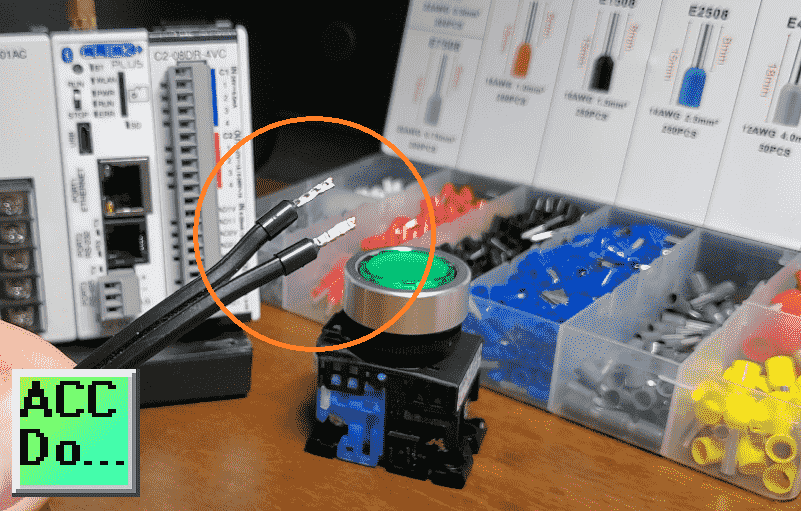
There are two different ways to connect the stranded copper wire to terminals. Using a soldering iron and tinning the stripped ends of the wire will keep the stranded wire together for the connection. However, this takes more time and is less neat and convenient than a ferrule.
 A ferrule is a thin tin-coated copper cylinder placed over a wire’s stripped end. The ferrule crimper will compress the tube into a square or hex shape, depending on how the wire connection is used. A square will work well with PLC (Programmable Logic Controller) terminals. Using a stranded wire directly into the terminal of the PLC is not recommended. This can cause the wire threads to bend and break, shorting out other terminal connections.
Watch the video below to see how to use ferrules.
Purchasing a wire ferrule kit will help you practice these connections.
How to Power the Click PLC – CPU Wiring
24VDC power is supplied to the CLICK PLUS CPU through a wiring connection from the power supply output to the 4-pin connector on the bottom of the CPU unit. 16–28 AWG wiring is supported. Crimping ferrules on all wire terminations are recommended for a more secure connection.
 The CLICK PLC family of components is designed to combine practical PLC features in a compact and expandable design with a simple-to-use philosophy. A powered CLICK PLUS PLC unit can be used as a complete PLC system with up to two Option Slot modules, or the system can be expanded by adding up to eight Stackable I/O modules. The CLICK PLC system does not require a mounting base. The CLICK PLUS PLC and I/O modules are connected via an expansion port on the right side of the PLC case. A variety of I/O modules is available for flexible and optimal system configuration. The CLICK PLUS PLC supports a short but helpful instruction set. There are 21 easy-to-use instructions that cover most applications suitable for this PLC class.
Two areas must be considered when determining the power required to operate a CLICK PLUS PLC system. The first is the power required internally by the CLICK PLUS PLC. This includes the internal logic-side power that the PLC provides to its Option Slot modules, connected I/O modules, and any device, such as a C-more Micro-Graphic panel, that is powered through one of the PLC’s communication ports. The second area is the power required by all externally connected I/O devices. This should be viewed as the field-side power required. The field-side power depends on the voltage used for a particular input or output device as it relates to the wired I/O point and on the calculated load rating of the connected device.
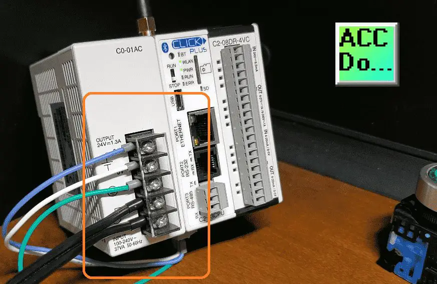 The Click C0-01AC (1.3 Amps) will provide enough power for all internal power consumption. 24VDC power is supplied to the CPU unit through a wiring connection from the power supply output to the 4-pin 24VDC input connector on the bottom of the CPU unit. The 24 VDC, 0 VDC, and ground are wired from the power supply to this connector.
 We are now ready to wire our lighted pushbutton to the Click PLC.
Wiring the Lighted Pushbutton to the Click PLC
Here is the wiring for our lighted pushbutton switch to our Click PLC.
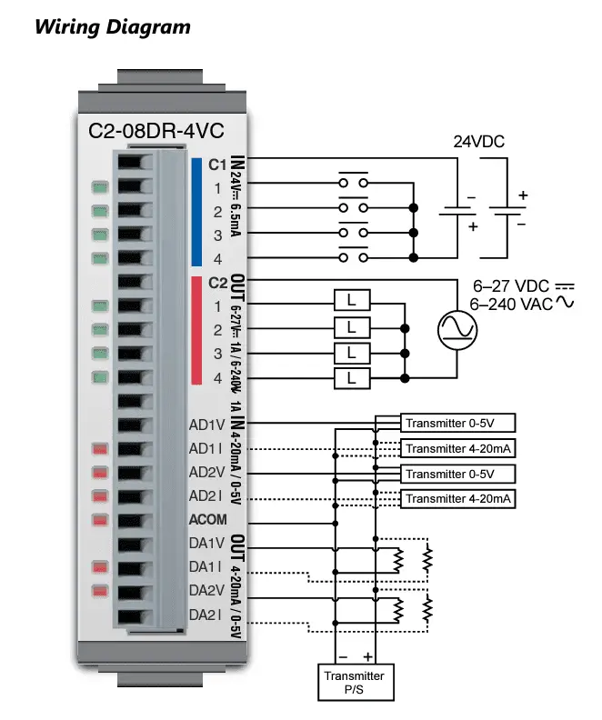 The 24-volt DC signal is wired to the input and output common of the PLC. The first input is wired to one side of the normally open contact of the pushbutton switch.
 The other side of the contact is wired to the 0-volt DC supply completing the circuit. Pushing the button will provide voltage to the input of the PLC.
 The PLC output common is at 24 volts DC. The first output is wired to the load side of the LED light. 0 volts DC is wired to the other contact terminal of the LED transformer. The circuit is complete when the output relay turns on, and the output LED will turn on.
The video below will demonstrate the wiring of the lighted pushbutton to the PLC.
Testing the PLC Inputs and Outputs
We can easily test our inputs and outputs of the Click PLC by using Data View in the Click programming software. Once connected online, the data view can manually monitor or set the inputs and outputs before ladder logic programming is written. This is an ideal way to test your IO and prove the correct wiring and terminations to the PLC.
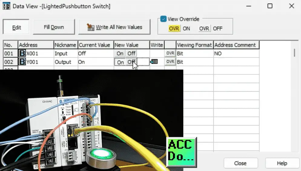 We can look at our first input, X001, by typing this into the address of our data view window. The current value will be displayed as on or off. We can physically push the button, and the current value will change. We can also see this on the LED light for the input.
Double-clicking on the output will turn the physical relay output on in the PLC. The pushbutton LED and the LED on the output IO will be on. Double-click on the off to turn the output off.
Ensuring that our inputs and outputs are working in the PLC is one of the steps in commissioning a PLC system.
Watch the video below to see how to test the PLC inputs and outputs. This will ensure that they are wired correctly and functional.
Programming the Click PLC
Our ladder logic program will use the single input push button. The output LED will turn on if the button is pressed continually for three seconds. Pressing the button again will turn the light off. This is the safest way of using one input to start and stop a physical output device.
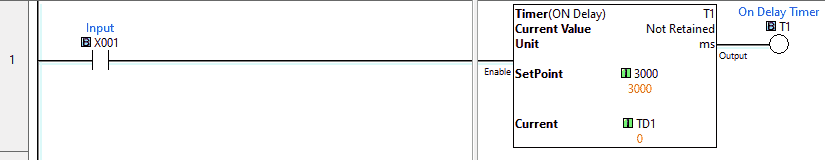 The first rung of our ladder logic will have input from our pushbutton switch. If on, then an on-delay timer is started. Clicking on the timer instruction, you will see the timing chart for this on-delay timer.
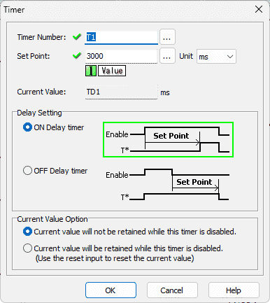 When the enabled is set, the timer will time for the duration set, and then the timer output will turn on. The time duration is set for 3000 milliseconds which is 3 seconds.
 Rung two will look at the leading edge of the input signal. This will trigger an output for one scan of the PLC when the input transitions from off to on. This will then turn on an internal bit, indicating that the input has been pressed.
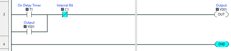 Our last rung uses the on-delay timer output and not the internal bit to turn on the output for the LED lighted pushbutton. When the output turns on, this will seal in the On Delay Timer contact, keeping the output on. The internal bit turning on will stop the output. This happens on the leading edge of the input signal.
Remember that a PLC uses a cyclic scan. This means that the inputs are read, the program logic is scanned, and outputs are set many times per second. The PLC solves the program ladder logic from left to right, top to bottom. The conditions from the previous rung are available for the next rung to use.
Testing the Click PLC One Input Start Stop Circuit
Using the ladder logic that we previously discussed, we will now test the operation of our lighted pushbutton switch. We will view the ladder logic status by using the status monitor under the monitor on the main menu. The data view can also be used to view the inputs and outputs, as we did when verifying the input and output wiring. See the video below to watch this in action.
The complete Click PLC Series will cover specific details on installing and using this programming software. It also includes information on wiring, communication, and other peripheral equipment that can be used with the Click PLC.
Pressing the push button will start our on-delay timer. Once the timer is finished timing, it will turn on the output. The pushbutton can now be released. The output will remain on due to the sealing contact on rung 3. Pressing the push button again will reset the output.
Test the circuit under many conditions. What happens when the output is on, and the power is removed? Currently, this is non-memory retentive, so the output turns off. This circuit is one of the safest, with one input controlling a start-stop.
To practice your programming skills, here are a couple of challenges for you.
1 – Add an output to sound an alarm for two seconds before the original output turns on. This means that the pushbutton, after 1 second, will sound an alarm for 2 seconds, and then the output will turn on.
2 – Make the output memory retentive.
Let me know how you make out in the comments below.
Watch the video below to see the operation of our program in the Click PLUS PLC.
Download the Click PLC program here.
Purchase your ferrule kit here with this associated link:
Video on this ferrule kit.
Click PLC Support Links
The Click PLC can be programmed using free Click programming software from Automation Direct. Here is a link to the software.
Version 3.31
Version 2.60
The entire Click PLC series can be found here. This includes the Click PLUS release.
All previous posts and information are still valid with the Click PLC line-up.
YouTube Click Playlist
YouTube Click PLUS Playlist
Click and Click PLUS PLC Overview
Click and Click PLUS PLC Videos from Automation Direct
Modbus Learning Links:
Simply Modbus Frequently Asked Questions
Modbus TCP/IP Overview – Real-Time Automation
All You Need to Know About Modbus RTU – Video
Watch on YouTube: How to Connect Pushbutton Switch to Programmable Controller
If you have any questions or need further information, please contact me.
Thank you,
Garry
If you’re like most of my readers, you’re committed to learning about technology. Numbering systems used in PLCs are not challenging to learn and understand. We will walk through the numbering systems used in PLCs. This includes Bits, decimals, Hexadecimal, ASCII, and Floating points. To get this free article, subscribe to my free email newsletter.
Use the information to inform others how numbering systems work. Sign up now. The ‘Robust Data Logging for Free’ eBook is also available as a free download. The link is included when you subscribe to ACC Automation.