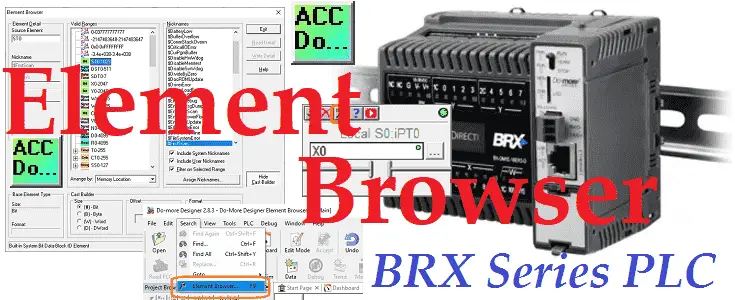
The element browser in the Do-More Designer software will display valid memory locations, add documentation, and show how to cast from one memory type to another.
We will be discussing the element browser and how to take advantage of this in your Do-More program. Let’s get started.
Previously in this BRX series PLC, we have discussed:
System Hardware – Video
Unboxing – Video
Installing the Software – Video
Establishing Communication – Video
Firmware Update – Video
Numbering Systems and Addressing – Video
First Program – Video
Monitoring and Testing the Program – Video
Online Editing and Debug Mode – Video
Timers – Video
Counters – Video
High-Speed IO – Video
Compare Instructions – Video
Math Instructions – Video
Program Control – Video
Shifting Instructions – Video
Drum Instruction – Video
Serial Communication – Modbus RTU to Solo Process Temperature Controller – Video
Data Logging – Video
Email – Text SMS Messaging Gmail – Video
Secure Email Communication Video
AdvancedHMI Communication – Modbus TCP – Video
Analog IO – System Configuration – Video
HTTP JSON Instructions – Video
Analog Dusk to Dawn Program – Video
INC DEC 512 Registers for DMX512 – Video
PID with PWM Output – Video
PID Ramp Soak Profile – Video
Do-More Simulator MQTT Publish / Subscribe – Video
BRX Do-More PLC MQTT Communications – Video
Stride Field Remote IO Modules Modbus TCP Ethernet
– Unboxing SIO MB12CDR and SIO MB04ADS Video
– Powering and Configuring Video
BRX Do-More PLC to Stride Field IO Modbus TCP – Video
BRX Do-More PLC Ethernet Remote IO Controller BX-DMIO
– Unboxing BX-DMIO Video
– Configuration and Programming Video
Modbus RTU TCP Remote IO Controller BX-MBIO
– Hardware Video
– Powering and Configuring Video
BRX Do-More PLC to Modbus Remote IO Controller BX-MBIO – Video
Modbus ASCII Protocol – Video
Peerlink Ethernet Communication – Video
HTTP Web Server – Video
Dynamic Web Pages – Video
BRX Do-More PLC FTP Client Get Put – Video
Our entire BRX Do-More series can be found here.
The programming software and manuals can be downloaded from the Automation Direct website free of charge.
Watch the video below to see the Element Browser in action on the Do-More Designer Software.
Do-More Designer (Software)
You can download the latest version of Do-More Designer here. This complete programming software comes with a PLC simulator. This free software is one of the best packages to learn PLC programming.
Calling the Do-More Element Browser
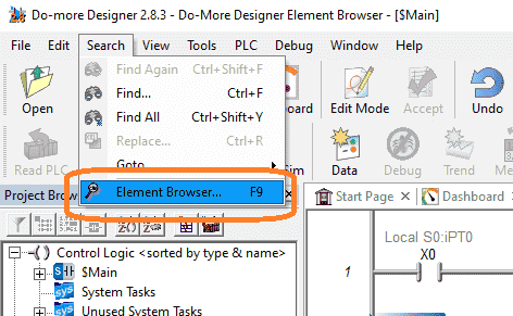
To call up the Element Browser use the Main menu | Search | Element Browser… You can also use the F9 on your keyboard.
When a program view is in normal display mode (Not in Edit Mode) the Element Browser can be invoked by double-clicking on an element or highlighting it with the cursor and pressing “Enter”.

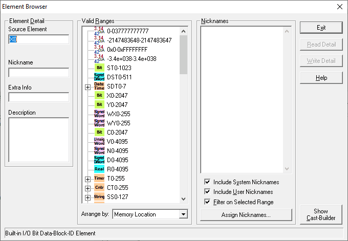
When in edit mode and writing your ladder logic calling up the addresses will default to the element picker in the Do-More Designer. Select the magnifying glass icon to call up the Element Browser.
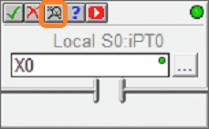
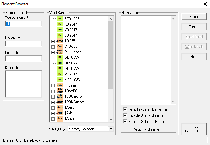
The address picker can be changed to the element browser using the Main menu | View | Options.
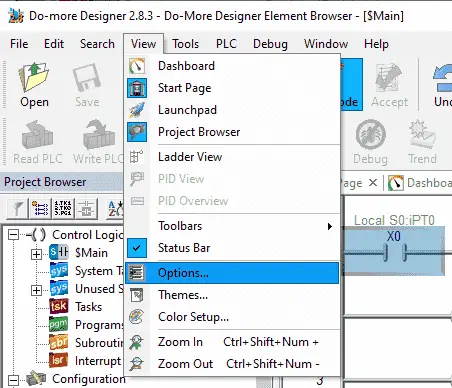
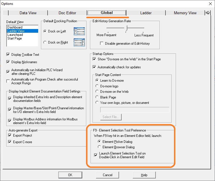
Select the Global tab. The default of Element Picker Dialog can be changed to Element Browser Dialog. My preference is to leave this as the default. The element picker shows used addresses.
Do-More Element Browser Parts
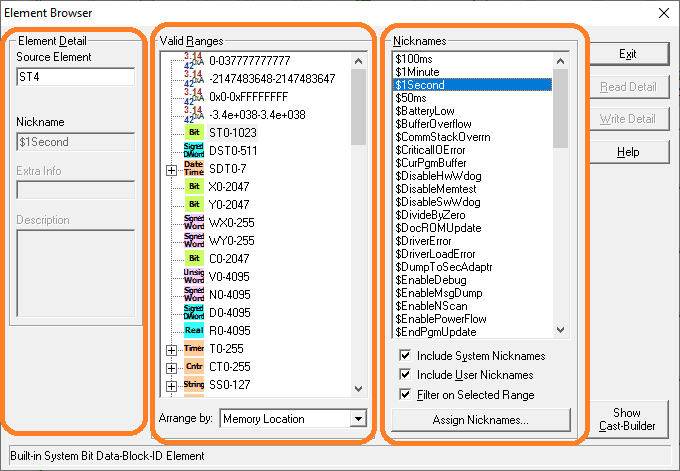
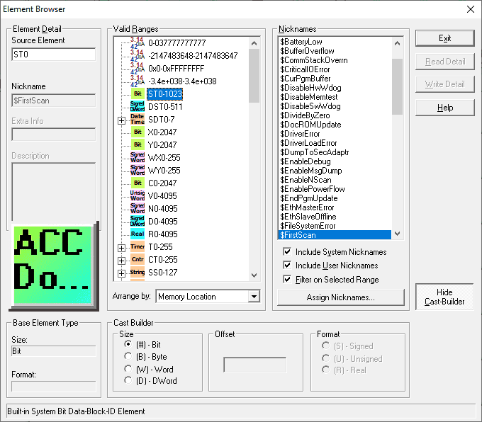
The Element Browser dialog is divided into three areas:
– Element Detail – Shows the documentation for the currently selected element. If the element is not being edited elsewhere in the system, the Nickname, Extra Info, and Description fields are enabled and you may edit them here.
- Source Element – this field always displays the currently selected element. If the element is an unassigned nickname, the source element field will be blank.
- Nickname – Nicknames must be unique, and can be 1 to 16 characters in length. Nicknames must begin with an alphabetic character or an underscore. Nicknames can consist of any combination of alphanumeric characters and underscores(‘_’, ‘a-z’, ‘A-Z’, 0-9), no spaces or punctuation marks are allowed, and must begin with a letter or an underscore.
- Extra Info – a 16 character user-assigned name for an element. If the Extra Info field is being used as a Symbolic Constant this will contain a numeric entry.
- Description – a 132 character field that can be used to provide a detailed description of the element.
– Valid Ranges – displays an exhaustive list of the valid ranges of elements for the current context. How the Element Browser has invoked controls what is displayed in the Valid Ranges list.
- Select Mode – this mode is enabled by clicking the ‘magnifying glass icon while editing an instruction, or pressing the F9 key while in the ladder editor. In this mode, the Element Browser is used as a guide in selecting a valid controller data element for the instruction you are editing. Since the Element Browser was called from the ladder editor, the ranges of the elements displayed will be correct for the current instruction.
- Browse Mode – this mode is enabled by opening the Element Browser from the menu or clicking the ‘magnifying glass icon on the toolbar. In this mode, the Element Browser is used to display the complete list of the ranges for the current controller. Instead of the “Select” button, there is an “Exit” button.
- Arrange by: – selects the sorting order options for the Valid Ranges list from the following:
- Memory Location – sorts the list by the Memory Configuration order
- Name – sorts the list alphabetically by Name
- Data Size – sorts the list by the size of the elements (Constants, Bits, Words, DWords, Structures )
– Nicknames – displays a list of the user-assigned nicknames (and optionally the system-defined nicknames) that fall within the ranges of elements in the current Valid Ranges list. When in “Select” mode, double-clicking on a nickname selects that nickname and exits the browser. Highlighting a nickname with a single click makes it the currently selected element.
- Include System Nicknames – when enabled, system-defined nicknames will be included in the list
- Include User Nicknames – when enabled, user-assigned nicknames will be included in the list
- Filter on Selected Range – when enabled, only nicknames that are in the same range as the selected item will be included in the list
- Assign Nicknames.. – button displays the Assign Nicknames dialog where you can associate any unassigned nicknames with an element.
Do-More Element Browser Addresses
The Do-More Element Browser will display the addresses available for the selected Do-More PLC controller.
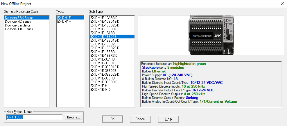
BRX BX-DM1E has been selected for our PLC controller.
Do-more’s program data is strongly typed. Strong typing means that the controller is aware of the size and format of each data element, and uses the data as appropriate without additional guidance from the user. Data blocks consist of elements of the same type.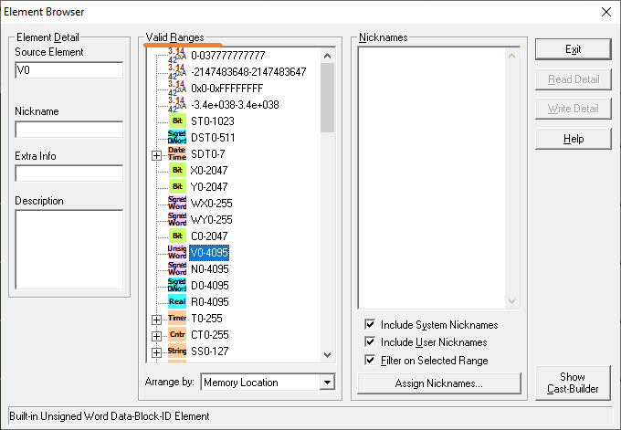
The following tables will give an overview of the data block areas.
System Status Bits / Values and Date / Time Structure – Numbering Systems
Note: System areas are not configurable. (Fixed)
| Data Block | Data Type | Default Range | Description |
| ST | Bit | ST0 – ST1023 | System Assigned Bits – Clock Flags etc. |
| DST | DWord | DST0-DST511 | System Assigned DWords – Scan Times etc. |
| SDT | Date / Time Structure | SDT0 – SDT7 | System Assigned Date / Time locations |
| UDT | Date / Time Structure | UDT0 – UDT31 | User Date / Time locations |
Physical Inputs and Outputs – BRX Do-More Numbering Systems
| Data Block | Data Type | Default Range | Description |
| X | Bit | X0 – X2047 | Discrete Inputs |
| Y | Bit | Y0 – Y2047 | Discrete Outputs |
| WX | Signed Word | WX0 – WX255 | Analog Inputs (-32768 to 32767) |
| WY | Signed Word | WY0 – WY255 | Analog Outputs (-32768 to 32767) |
| RX | Real (floating point) | RX0 – RX255 | Scaled Analog Inputs (-3.4e+038 to +3.4e+038) |
| RY | Real (floating point) | RY0 – RY255 | Scaled Analog Outputs (-3.4e+038 to +3.4e+038) |
Internal Bits and Numeric Values – BRX Do-More Numbering Systems
| Data Block | Data Type | Default Range | Description |
| C | Bit | C0 – C2047 | Control Relays |
| V | Unsigned Word | V0 – V4095 | 16 Bit Unsigned registers (0 to 65535) |
| N | Signed Word | N0 – N4095 | 16 Bit Signed registers (-32768 to 32767) |
| D | Signed DWord | D0 – D4095 | 32 Bit Signed registers (-2147483648 to 2147483647) |
| R | Real (floating point) | R0 – R4095 | 32 Bit Real registers (-3.4e+038 to +3.4e+038) |
Timers and Counters / Strings – BRX Do-More Numbering Systems
| Data Block | Data Type | Default Range | Description |
| T | Timer Structure | T0 – T255 | Timers |
| CT | Counter Structure | CT0 – CT255 | Counters |
| SL | String | SL0 – SL63 | Long Strings – 256 characters each |
| SS | String | SS0 – SS127 | Short Strings – 64 characters each |
Communications – Peerlink / KSequence Client(Master) / Modbus Client(Master)
| Data Block | Data Type | Default Range | Description |
| PL | Unsigned Word | PL0 – PL255 | Used to share data with PLC’s (Peerlink) |
| PL | Peerlink Structure | PL – Header | |
| DLX | Bit | DLX0 – DLX777 | KSequence – Octal – Referenced by ERM modules |
| DLY | Bit | DLY0 – DLY777 | KSequence – Octal – Referenced by ERM modules |
| DLC | Bit | DLC0 – DLC777 | KSequence – Octal – Referenced by ERM modules |
| DLV | Unsigned Word | DLV0 – DLV3777 | KSequence – Octal – Referenced by ERM modules |
| MI | Bit | MI1 – MI1023 | Modbus – Numbered in decimal |
| MC | Unsigned Word | MC1 – MC1023 | Modbus – Numbered in decimal |
| MIR | Bit | MIR1 – MIR2047 | Modbus – Numbered in decimal |
| MHR | Unsigned Word | MHR1 – MHR2047 | Modbus – Numbered in decimal |
Do-More Element Browser Nickname
You can document memory areas that you are using in your program using the element browser. This can be done in any mode when looking at the program.

Once you have typed in the nickname, extra info or description select the write detail button. This will save the information.
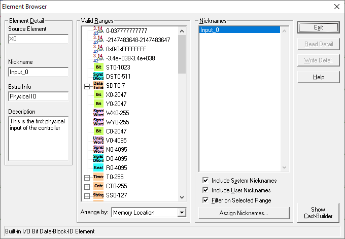
The new nickname will now appear under the Nickname heading in the element browser.
Element Browser Memory Casting
Casting is the ability to convert one memory type into another memory type. The Do-More has a cast builder that will help you get the syntax correct for the conversions. Here is a link for a review of numbering systems used in programmable controllers.
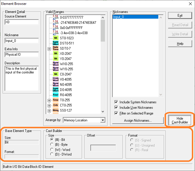
Select the Show/Hide Cast-Builder button to display or hide the cast builder at the bottom of the element browser.
In the BRX Do-More Controller, there are three types of casting.
Extraction casts will isolate a bit, byte, or word from a larger element.
| Access Size | Syntax | Range | Description |
| Bit | :# | # = 0 to 7 (Bytes), 0-15 (Words), 0 to 31 (DWords) | Isolates a Bit from a Byte, Word, or DWord element |
| Byte | :B# | # = 0 to 1 (Words), 0 to 3 (DWords) | Isolates a Byte from a Word or DWord element |
| Word | :W# | # = 0 to 1 (DWords) | Isolates a Word from a DWord element |
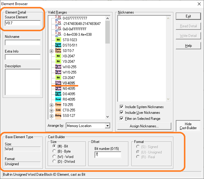
Example: V0:7 means this is now bit number 7 of the V0 word.
Aggregation casts will group multiple elements into a larger element.
| Access Size | Syntax | Description |
| Byte | :B | Combines 8 bits into a Byte |
| Word | :W | Combines 16 bits or 2 Bytes into a Word |
| DWord | : D | Combines 32 bits, 4 Bytes, or 2 Words into a DWord |
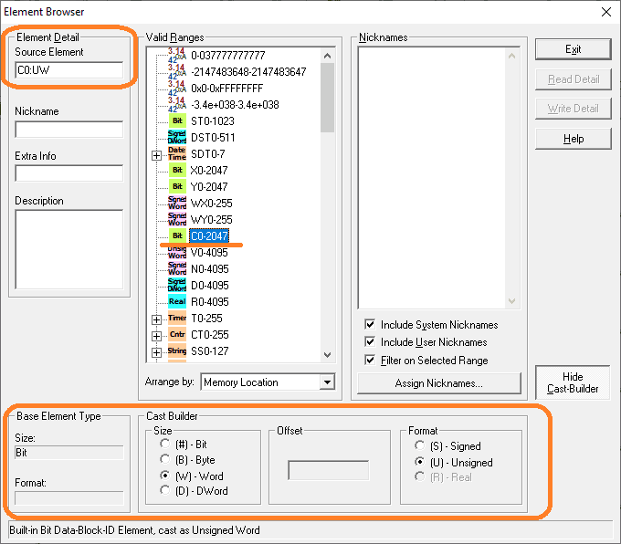
Example: C0:UW will take bits C0 to C15 and treat them as an unsigned 16-bit word.
Format casts will reinterpret the format of data in the element.
| Format | Syntax | Description |
| Unsigned Integer | :U | Reinterprets data as Unsigned Integer |
| Signed Integer | :S | Reinterprets data as Signed Integer |
| Real | :R | Reinterprets data as Floating Point |
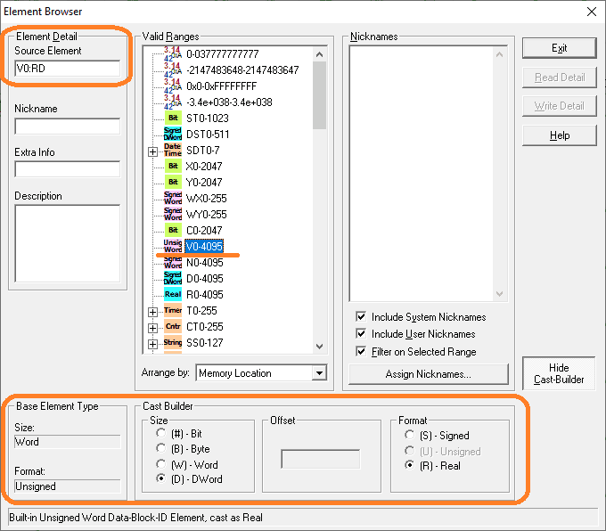
Example: V0:RD will take V0 and V1 as a real double 32-Bit word.
Watch the video below to see how to use the Do-More Designer Element Browser with the Do-More PLC controllers.
BRX Series PLC from Automation Direct – Power to deliver
Overview Link (Configure and purchase a system)
Manuals and Product Inserts (Installation and Setup Instruction)
Do-More Designer Software (Free Download Link) – The software will contain all of the instruction sets and help files for the BRX Series PLC.
Watch on YouTube: Do-More Designer Element Browser
If you have any questions or need further information please contact me.
Thank you,
Garry
If you’re like most of my readers, you’re committed to learning about technology. Numbering systems used in PLCs are not difficult to learn and understand. We will walk through the numbering systems used in PLCs. This includes Bits, Decimal, Hexadecimal, ASCII, and Floating Point. To get this free article, subscribe to my free email newsletter.
Use the information to inform other people how numbering systems work. Sign up now. The ‘Robust Data Logging for Free’ eBook is also available as a free download. The link is included when you subscribe to ACC Automation.

