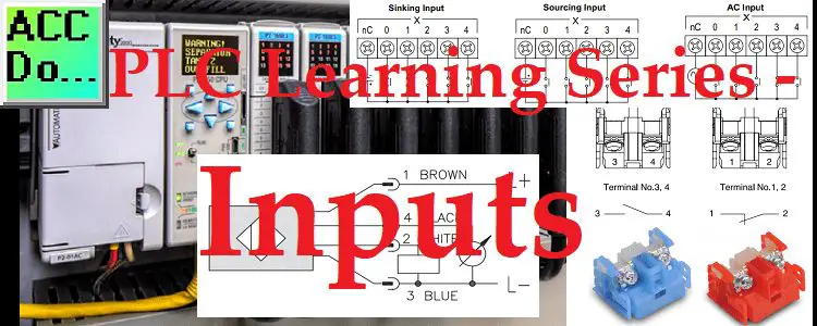
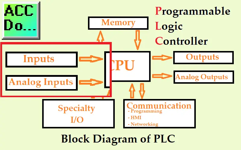
PLC inputs are one component of our PLC block diagram. The output actions of the PLC will be controlled based on the inputs. We will be looking at digital and analog inputs that can be wired to the programmable logic controller.
We will be looking at wiring of a normally open (NO) push button, normally closed (NC) push button, 3 wire PNP sensor, and an analog sensor to the PLC. These will all be sinking inputs. Let’s get started.
Previously in this PLC Learning Series:
PLC Training Series – Tutorial for Everyone – Video
What are PLC Inputs?
The term PLC input usually refers to the physical devices connected to the programmable logic controller. Inputs are usually isolated from the CPU of the PLC through light. This isolation is the reason that if an input is destroyed, the PLC can still function. Usually, the input can be corrected and a new input card can be placed on the PLC. Alternately, the input can be corrected and the PLC input can be programmed for another input address.
Note: You must refer to the specification from the manufacturer to determine how the inputs are protected.
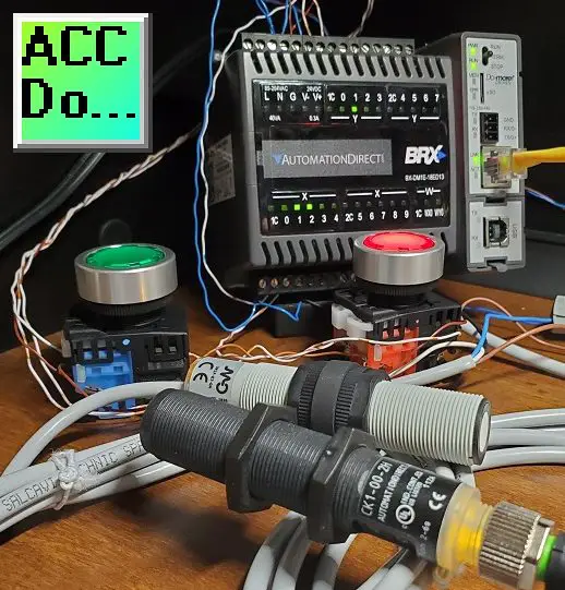
These input devices give the PLC information about what they are controlling. Push buttons, switches, limit sensors, distance measurement, are just a couple of examples of PLC inputs. Operator inputs through a human-machine interface (HMI) are also a form of PLC inputs that we will be discussing later. Physical inputs are what we will be looking to wire and understand.
Here are the specifications for the discrete inputs on our BRX Do-More PLC.
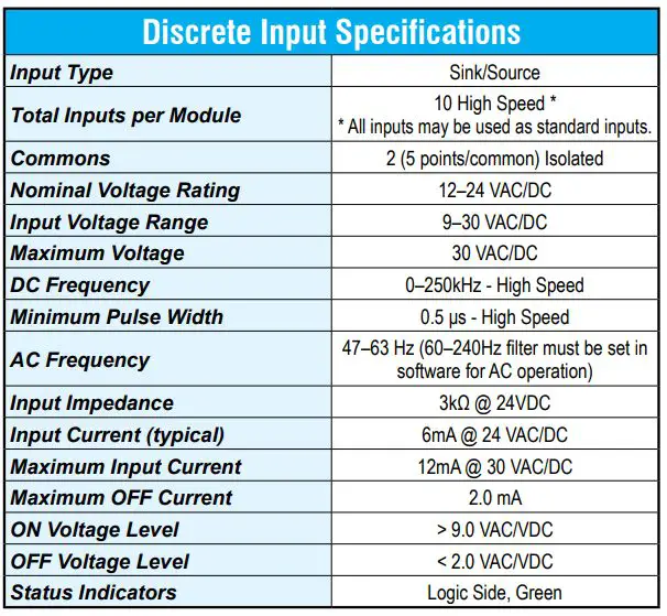
BX-DM1E-18ED13
Technical Specifications
You will see that we have 10 discrete inputs. 5 input points per common.
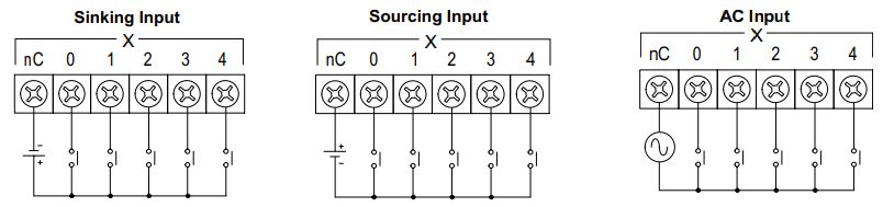
The power supply per common can be sinking (0VDC on the common), sourcing (+VDC on the common), or AC inputs. Each of the individual inputs completes its own circuit. The input point to the common is called the input load (Impedance).
Discrete vs Analog PLC Inputs
Discrete and analog PLC inputs are the usual method for specifying the PLC. Specifying the physical number of discrete inputs and analog inputs helps to determine the size of PLC or the ability of the PLC.
Discrete or Digital inputs refer to an on/off or I/0 type of input. They will only have these two states.
Analog inputs will refer to a range expressed in the units specified for the device. An example would be an ultrasonic sensor. This analog input sensor can measure distance. The output is a range that can be expressed as inches, feet, yards, etc.
Discrete PLC Inputs
Discrete digital inputs as mentioned before are either on or off. Without touching the button or a sensor seeing an object, this is called the normal state. If no voltage is on the input to the PLC then this is called a normally open input. If voltage exists and the input light is on in the normal start, then this is called a normally closed input. Typically start pushbuttons are normally open and stop pushbuttons are normally closed. Sensors can be sometimes wired or programmed either way depending on the operation you require for your industrial application.
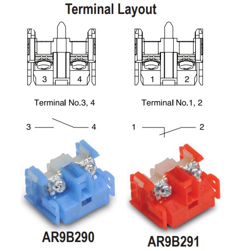
Here is an example of some terminal blocks for push buttons. They are usually color-coded. Red for normally closed and blue for normally open. This aids in troubleshooting the individual input circuits and voltages expected.
The above diagram has two inputs. A normally open (NO) and a normally closed (NC). When we talk about normally open and close, think of the condition of the input if no one touches anything. A normally open contact will not turn on the input to the PLC card in its ‘normal state. The normally closed contact will turn on the input to the PLC card in its ‘normal state.
Watch the video below to see the push buttons in action connected to our PLC.
What do Sinking and Sourcing mean?
You will often hear about sinking and/or sourcing PLC inputs. The PLC input acts as a load on the input circuit.
If the common to the input is 0VDC then this is a sinking input. The +VDC coming from the input point is being connected to 0VDC to complete the circuit. This is sometimes referred to also as negative or zero switching.
If the common to the input is +VDC then this is a sourcing input. The 0VDC coming from the input point is being connected to +VDC to complete the circuit. This is sometimes referred to also as positive or plus switching.
As you can see, it is just a matter of looking at the reference of the PLC input point to determine sinking or sourcing. All inputs must be one or the other per the common input point of the PLC. Mixing sourcing and sinking inputs on the same PLC common point will create a short circuit for the input supply and may damage the PLC input. The common practice is to have the entire PLC either sourcing or sinking.
Most modern PLC manufacturers will have sinking and sourcing inputs. It will depend on how the common point for the input is wired to the supply voltage.
Note: Check the manufacturers’ specifications before wiring to ensure that this is the case.
What are NPN and PNP Sensors?
The sinking and sourcing terms actually come from wiring 3 wire DC sensors. NPN and PNP refer to the output bipolar junction transistor (BJT) of the sensor.
NPN stands for Negative-Positive-Negative and PNP stands for Positive-Negative-Positive. These are the doping materials that allow current amplification in the transistor. PNP sensors are sometimes called “sourcing sensors” because they source positive power to the output. NPN sensors are sometimes called “sinking sensors” because they sink ground to the output. What gets confusing is understanding the point of view. The sensor point of view is from the switch. A load on the sensor is the opposite of the switch point of view in the circuit.
The main thing to remember is that the load (PLC Input) is sourcing for an NPN sensor and sinking for a PNP sensor.
Note: Always refer to the specification sheets for the sensor that you are connecting to the PLC for the wiring diagram.
CK1-00-2H – Capacitive Proximity Sensor NPN/PNP, N.O./N.C. selectable
Technical Specifications
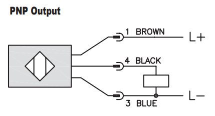
Here is an example of the wiring diagram of the PNP sensor. The rectangular box represents the load. In our case, the load is the PLC. So the blue wire would go to the 0VDC supply and common of the PLC input. The black would be connected to the PLC input. The brown would connect to the +VDC supply.
Watch the video below to see the wiring and operation of this sensor.
Analog PLC Input
An analog input converts a voltage or current level into a digital value that can be stored and processed in the PLC. Standard industrial voltages are 0-10 or 1-5 volts DC or 0-20 or 4-20 mA current.
Analog voltage inputs are the most common. I believe this to be true because they are easy to wire and test with a multi-meter. 0 – 10 VDC analog is the most popular but has the greatest risk of being influenced by noise.
Analog current inputs are better for long-distance runs and are less prone to noise. You can also place a 250-ohm resistor on an analog 4 – 20 mA current sensor and get a voltage output of 1 – 5 VDC. This is just using ohm’s law.
Note: Always refer to the manufactures specifications for the wiring diagrams for your analog sensor or signal.
BX-DM1E-18ED13
Technical Specifications
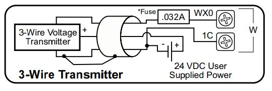
Here is the wiring diagram in the PLC specifications for an analog voltage 3 wire transmitter to the PLC input.
Wiring Analog Inputs
UK1F-E7-0A – 0 to 10 VDC analog output, PNP, N.O./N.C. selectable
Technical Specifications
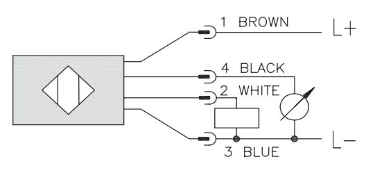
Here is the wiring diagram for the ultrasonic analog sensor. The white wire is a switch that will give us a discrete signal. The circle with the arrow represents our analog output load, which is the PLC analog input. The black wire is our input wire. The blue wire is a 0VDC supply and common point for the analog input. The brown wire is our +VDC supply voltage.
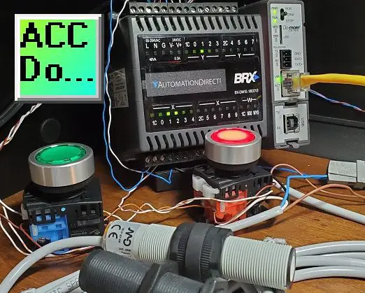
Watch the video below to see the analog sensor wired and operating in our PLC.
PLC Beginner’s Guide to PLC Programming
There are many different PLC manufacturers with different hardware and software. All of the programmable logic controllers have similar basic features. Here is how I would approach learning about basic PLCs.
Once you are familiar with the basics of the PLC you would then learn specifics for the controller that you will be programming.
This is the easiest way to learn about PLC programming.
Watch on YouTube: PLC Learning Series – What are Inputs?
If you have any questions or need further information please contact me.
Thank you,
Garry
If you’re like most of my readers, you’re committed to learning about technology. Numbering systems used in PLCs are not difficult to learn and understand. We will walk through the numbering systems used in PLCs. This includes Bits, Decimal, Hexadecimal, ASCII, and Floating Point.
To get this free article, subscribe to my free email newsletter.
Use the information to inform other people how numbering systems work. Sign up now.

The ‘Robust Data Logging for Free’ eBook is also available as a free download. The link is included when you subscribe to ACC Automation.