We will now look at P1AM Arduino Modbus TCP communication to the C-More Micro EA3 HMI. This will be communicating the Ethernet Modbus TCP protocol. The P1AM will be the server (slave) and the EA3-T4CL the client (master).
There was a recent question on the Automation Direct Customer Forums that asked, “How do I connect an HMI C-more EA3-T4CL and P1AM PLC?“.
We will explain how to connect this to our P1AM-ETH Industrial Arduino Ethernet Shield.
The P1AM Example from Automation Direct on GitHub will be used.
P1AM-Examples/tree/master/P1AM-100_ModbusTCP_Server_HMI
We will be using the C-More Micro EA3-T4CL HMI that is posted. Let’s get started.
Previous posts in this Productivity Open Arduino Compatible Industrial Controller Series
A full list can be obtained at the following location:
Productivity Open (P1AM-100) Arduino Controller
Productivity Open Arduino Controller Hardware
– Starter Kit Unboxing Video
– Powering Up Video
Installing the Software – Video
First Program – Video
Program Structure – Video
Variables Data Types – Video
Serial Monitor COM – Video
Program Control – Video
Operators – Video
GPIO Inputs and Outputs – Video
Math Instructions – Video
Time Instructions – Video
P1000 Expansion Analog Combination Module – Video
P1000 Expansion Digital Inputs and Outputs Part 1 – Video
P1000 Expansion Digital Inputs and Outputs Part 2 – Video
Watchdog Timer – Video
P1000 Expansion Thermocouple Module – Video
PID Control – Video
Watch the video below to see a sample program (sketch) of the P1AM-ETH Modbus TCP Server communicating to our C-More micro Modbus TCP client HMI.
P1AM-ETH
Specifications
The P1AM-ETH is an industrially rated MKR format shield based on the WIZnet W5500 chip that adds ethernet connectivity to the P1AM-100. The P1AM-ETH uses SPI to communicate with the P1AM-100 or other MKR format CPU. The P1AM-ETH uses the Arduino Ethernet library which comes standard with the Arduino IDE.
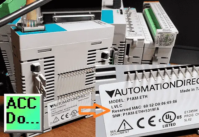
The MAC (Media Access Control) address is the physical hardware identification number. This is printed on the right-hand side label of our P1AM-ETH unit.
We will need this number for our program.
Modbus TCP Server (Slave)
Our sketch (program) comes from the sample on GitHub that will turn our P1AM-ETH into a Modbus TCP Server and give access to our P1 (Productivity 1000) input and output modules.
Libraries Required
The first thing that we must do is to ensure that the libraries (dependencies) that we need are installed on our Arduino IDE.
https://github.com/arduino-libraries/ArduinoModbus
https://github.com/arduino-libraries/ArduinoRS485
Note: The Arduino Modbus Library depends on the Arduino RS485 so both must be installed.
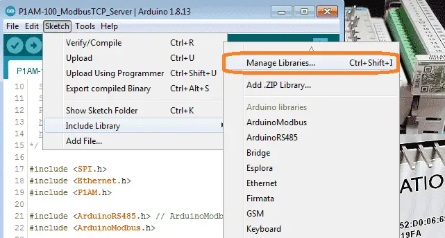
Call up the library by using the main menu | Sketch | Include Library | Manage Libraries… Alternatively, you can use the short cut of Ctrl+Shift+I.
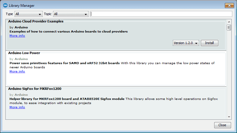
Type in ArduinoModbus on the top line to call up the library functions available.
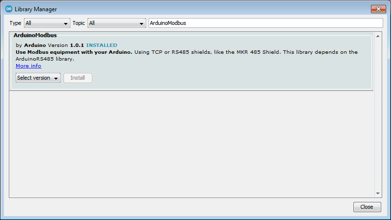
If it is not installed then select the latest version and install.
Type in ArduinoRS485 on the top line to call up the library functions available.
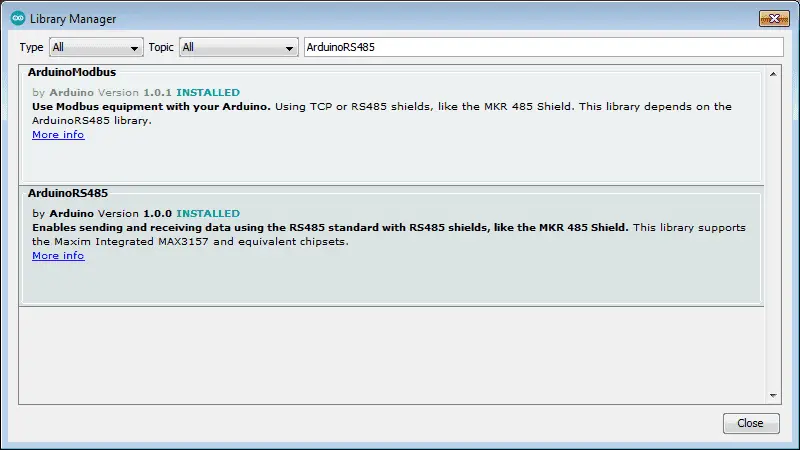
If it is not installed then select the latest version and install.
Select close to close the library manager window.
Note: Both libraries appear when typing Arduino RS485 because of the dependency between them.
Modbus TCP Server Sample Program (Sketch)
A Modbus server will do nothing until a client asks for information. The server program will create variables that are available for the client to read or write. There are four types of variables in Modbus.
Discrete Output Coils 0xxxx
Discrete Input Contacts 1xxxx
Analog Input Registers 3xxxx
Analog Output Holding Registers 4xxxx
This sample program is the exact same as the sample on GitHub. The purpose is to create a Modbus TCP server for the P1AM-ETH with access to productivity 1000 (P1) input and output modules.
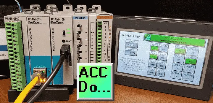
In our example, we have two P1 modules to the right-hand side of the P1AM CPU. The P1-08SIM (8 point simulator input card) and P1-16TR (16 point relay output card).
This sketch creates a Modbus TCP Server for up to 8 connections. Slot1 Inputs are mapped to Modbus Input Bits 100001 to 100008. Slot2 Outputs are controlled by Modbus Coil Bits 000001 to 000008. Modbus Holding Register 400001 is always incrementing.
Here is the sample program (sketch):
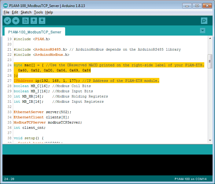
We have ensured that the MAC address is set according to the physical card and the IP is set according to our network.
/*
Modbus TCP Server for P1AM-ETH with
access to P1 Input/Output Modules
This sketch creates a Modbus TCP Server for up to 8 connections.
Slot1 Inputs are mapped to Modbus Input Bits 100001 to 100008.
Slot2 Outputs are controlled by Modbus Coil Bits 000001 to 000008.
Modbus Holding Register 400001 is always incrementing.
The P1AM-100 CPU will require external 24vdc power
for the IO modules to function. This example uses
Serial.print() to display status information. The
Serial Monitor must be running for the sketch to start.
Required Libraries that need to be installed.
https://github.com/arduino-libraries/ArduinoModbus
https://github.com/arduino-libraries/ArduinoRS485
*/

#include
#include
#include

#include // ArduinoModbus depends on the ArduinoRS485 library
#include

byte mac[] = { //Use the �Reserved MAC� printed on the right-side label of your P1AM-ETH.
0x60, 0x52, 0xD0, 0x06, 0x69, 0x86
};
IPAddress ip(192, 168, 1, 177); //IP Address of the P1AM-ETH module.
boolean MB_C[16]; //Modbus Coil Bits
boolean MB_I[16]; //Modbus Input Bits
int MB_HR[16]; //Modbus Holding Registers
int MB_IR[16]; //Modbus Input Registers

EthernetServer server(502);
EthernetClient clients[8];
ModbusTCPServer modbusTCPServer;
int client_cnt;

void setup() {
Serial.begin(115200);
while (!Serial){}// wait for serial port to connect.
Serial.println("Modbus TCP Server and Module I/O Example");
while (!P1.init()){} ; //Wait for P1 Modules to Sign on
Ethernet.begin(mac, ip);
server.begin(); // start the server to begin listening

if (!modbusTCPServer.begin()) { // start the Modbus TCP server
Serial.println("Failed to start Modbus TCP Server!");
while (1); //If it can't be started no need to continue, stay here forever.
}

modbusTCPServer.configureCoils(0x00, 16); //Coils
modbusTCPServer.configureDiscreteInputs(0x00, 16); //Discrete Inputs
modbusTCPServer.configureHoldingRegisters(0x00, 16); //Holding Register Words
modbusTCPServer.configureInputRegisters(0x00, 16); //Input Register Words

Serial.println("Done with setup()");
}

void loop() {
EthernetClient newClient = server.accept(); //listen for incoming clients
if (newClient) { //process new connection if possible
for (byte i = 0; i < 8; i++) { //Eight connections possible, find first available.
if (!clients[i]) {
clients[i] = newClient;
client_cnt++;
Serial.print("Client Accept:"); //a new client connected
Serial.print(newClient.remoteIP());
Serial.print(" , Total:");
Serial.println(client_cnt);
break;
}
}
}

//If there are packets available, receive them and process them.
for (byte i = 0; i < 8; i++) {
if (clients[i].available()) { //if data is available
modbusTCPServer.accept(clients[i]); //accept that data
modbusTCPServer.poll();// service any Modbus TCP requests, while client connected
}
}
for (byte i = 0; i < 8; i++) { // Stop any clients which are disconnected
if (clients[i] && !clients[i].connected()) {
clients[i].stop();
client_cnt--;
Serial.print("Client Stopped, Total: ");
Serial.println(client_cnt);
}
}

//Read from P1-08SIM Input Module and then write into Modbus memory
int Slot1_Inputs = P1.readDiscrete(1,0); //Read from P1-08SIM Input Simulator Module
for (int i=0;i<8;i++){
MB_I[i]=Slot1_Inputs&(1<<i);
}
updateInputs(); //Write current state of the Modbus Inputs into MB_I[]

//Read from Analog Input Modules and then write into Modbus memory
updateInputRegisters(); //Write current state of the Modbus Inputs into MB_IR[]

updateCoils(); //Read current state of the Modbus Coils into MB_C[]
for (int i=0;i<8;i++){
P1.writeDiscrete(MB_C[i],2,i+1);//Data,Slot,Channel ... Channel is one-based.
}

updateHoldingRegisters(); //Read current state of the Modbus Registers into MB_HR[]
MB_HR[0]++; //TestApp, increment the Modbus Register 400000 just to have data changing.
modbusTCPServer.holdingRegisterWrite(0,MB_HR[0]);
}

void updateCoils() {//Read the Coil bits from the Modbus Library
for (int i=0;i<16;i++){
MB_C[i] = modbusTCPServer.coilRead(i);
}
}

void updateInputs() { //Write the Input bits to the Modbus Library
for (int i=0;i<16;i++){
modbusTCPServer.discreteInputWrite(i,MB_I[i]);
}
}

void updateHoldingRegisters() {//Read the Holding Register words from the Modbus Library
for (int i=0;i<16;i++){
MB_HR[i] = modbusTCPServer.holdingRegisterRead(i);
}
}

void updateInputRegisters() { //Write the Input Registers to the Modbus Library
for (int i=0;i<16;i++){
modbusTCPServer.inputRegisterWrite(i,MB_IR[i]);
}
}
We now have our completed Modbus server program for our industrial Arduino.
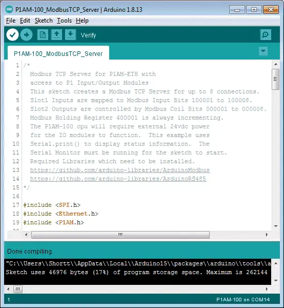
Verify the program.
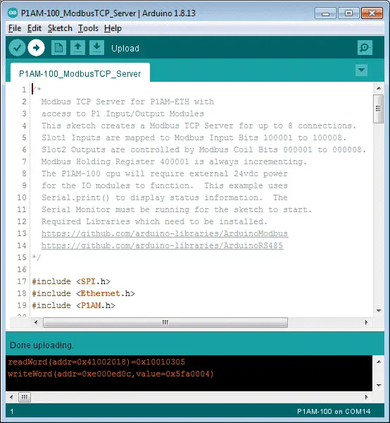
Upload the program.
We can now move onto the Modbus client.
C-More Micro EA3-T4CL
Our complete cmore micro-series can be found here. This will take you through all of the features of this versatile human-machine interface. HMI.
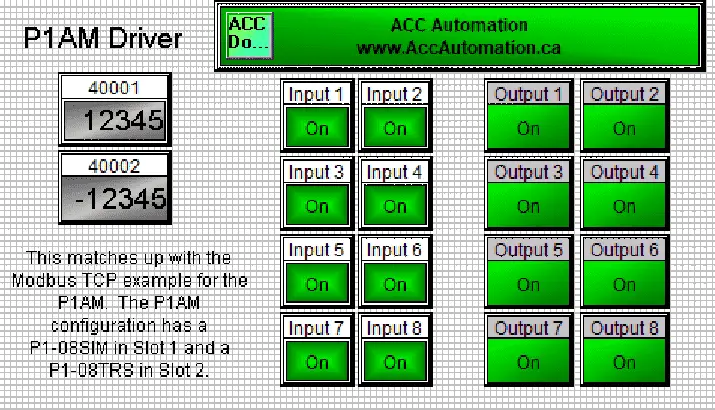
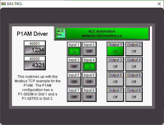
We will have one screen that will be called a P1AM driver.
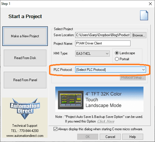
Start a new project select the name and HMI type as EA3-T4CL. Select PLC Protocol.
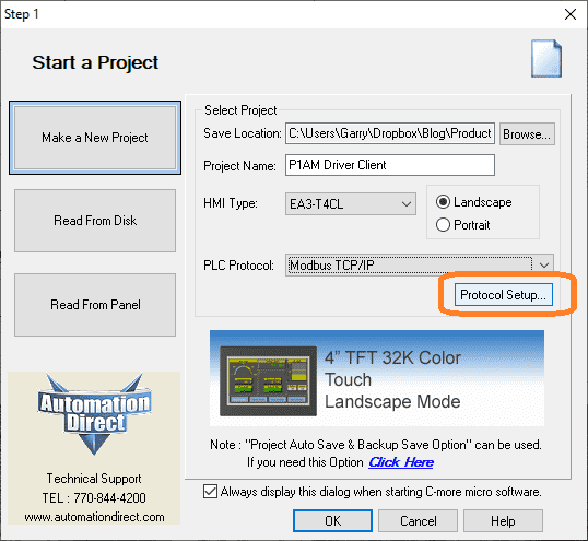
Select Modbus TCP/IP as the PLC Protocol. Select protocol setup…
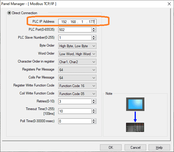
Enter the IP address of the P1AM-ETH card that we set above in the sketch. (Program)
We will leave all of the other parameters as their default values. Select OK.
Tag Name Database
Call up the tag name database by using the main menu | Database | Tag Name Database…
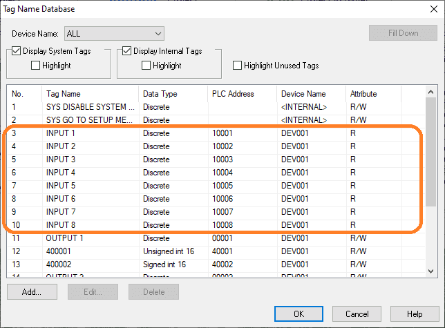
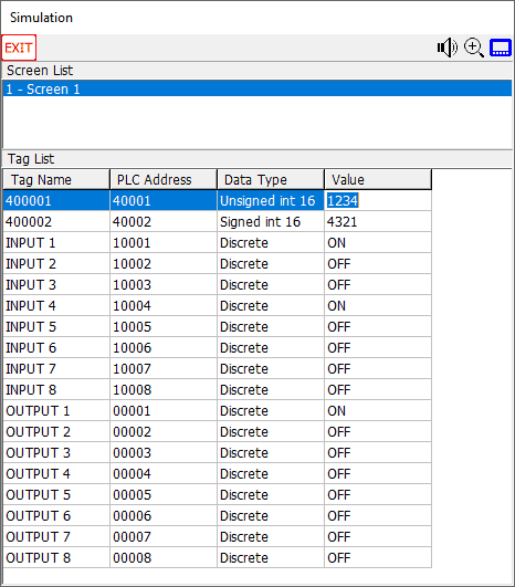
We will put in the addresses for the 8 input bits. The Modbus address will be 10001 to 10008 for the simulator card inputs in slot 1 of our P1AM.
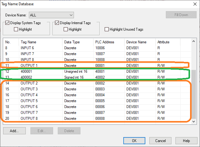
The 8 outputs will be addressed with Modbus address 00001 to 00008. This is in the second slot of our P1AM and is a relay output card.
Address 400001 will be a Modbus holding register that we will read from the Arduino P1AM. This will automatically be updated by 1 each scan of our P1AM program. Address 400002 will be a holding register that we will write to from the C-More Micro unit.
Our HMI will have one screen.
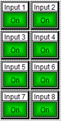
We will use the indicator light for each of our input variables.
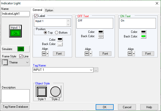
Select the tag names that we set up in the tag name database.
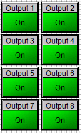
We will use push buttons for the control of our relay output card.
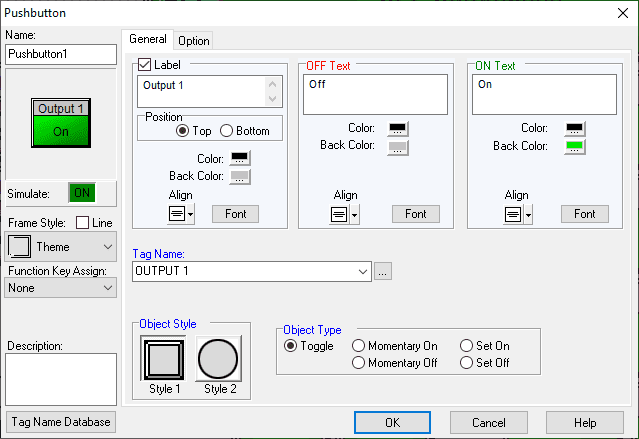
Select the tag names that we set up in the tag name database. The object type will be a toggle. When this is selected it will allow us to turn the output on/off with the same input pushbutton.
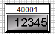
The numeric display will show us the incremented value from the P1AM.
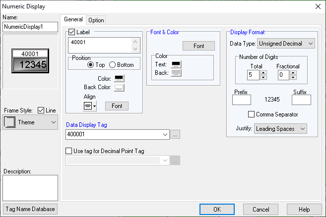
Select 5 digits of an unsigned decimal value.
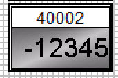
We will use the numeric entry for the Modbus holding register 40002.
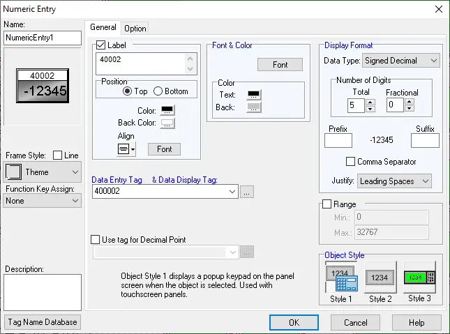
This will be a 5 digit signed decimal entry. The object style will be a pop-up the numeric keypad.
Our screen is now complete.
We can use the simulator to test our program before downloading it to the HMI.
Download the C-More Micro program into the EA3-T4CL HMI screen.
We can now run our programs together.
Watch the video below to see the operation of our productivity open industrial Arduino controller communicating Modbus TCP to our C-More micro-unit.
Download the P1AM-100 sample sketch and C-More Micro program here.
Productivity Open Arduino Compatible Links:
Product Hardware
– Productivity Open (Automation Direct)
– P1AM-100 Specifications
– Productivity Open User Manual
– Configure a Productivity Open Arduino-based Controller
– Open Source Controllers (Arduino-Compatible)
– Productivity Open Documentation (Facts Engineering)
– P1AM Design Files
Software
– Arduino IDE (Integrated Development Environment)
– P1AM-100 library (Easy Interface for controlling P1000 Modules)
– Productivity Blocks (Development Timesaver)
– Productivity Blocks Documentation (Wiki)
Community
– Automation Direct Forum – Open Source Devices
Modbus Learning Links:
Simply Modbus Frequently Asked Questions
Modbus TCP/IP Overview – Real-Time Automation
All You Need to Know About Modbus RTU – Video
Next time we will look at connecting an EA9-RHMI (Headless HMI with Remote Access) to our Ethernet industrial shield on our P1AM-100 Arduino Industrial Controller.
Watch on YouTube: Productivity Open P1AM Industrial Arduino Modbus TCP to C-More Micro EA3
If you have any questions or need further information please contact me.
Thank you, Garry
If you’re like most of my readers, you’re committed to learning about technology. Numbering systems used in PLC’s are not difficult to learn and understand. We will walk through the numbering systems used in PLCs. This includes Bits, Decimal, Hexadecimal, ASCII and Floating Point. To get this free article, subscribe to my free email newsletter.

The ‘Robust Data Logging for Free’ eBook is also available as a free download. The link is included when you subscribe to ACC Automation.