Timing Diagram NOT Just Used for a Timer

Logic circuits in a PLC ladder logic program are either on or off. The inputs change, which will affect the outputs. This can be expressed in a timing diagram. The timing diagram or chart will show you how the ladder logic program will respond to the changing states of the inputs and outputs. This visual … Read more

PLC Learning Series – Programming Steps

PLC Learning Series – Programming Steps

Developing a programmable logic controller (PLC) program can be broken down into five steps. These programming steps are as follows: Five Steps to PLC Program Development Step 1 – Define the task Step 2 – Define the Inputs and Outputs Step 3 – Develop a logical sequence of operation Step 4 – Develop the PLC … Read more

PLC Learning Series – Memory Backup

PLC Learning Series – Memory Backup

PLC memory is very similar to personal computer memory. There is the operating system and firmware of the processor and connected modules. PLC programs and data that are used by the program are also stored in the memory. We will now look at the basic understanding of memory in the PLC. Looking at two examples … Read more

PLC Learning Series – What are Outputs?

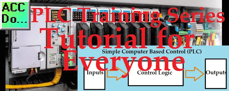
PLC Learning Series - What are Outputs?

PLC outputs are the next component of our PLC block diagram. The PLC program will control the outputs of the PLC. Controlling outputs is one way to get the inputs to change. We will be looking at digital and analog outputs that can be wired to the programmable logic controller. PLC troubleshooting outputs will also … Read more

PLC Training Series – Tutorial for Everyone

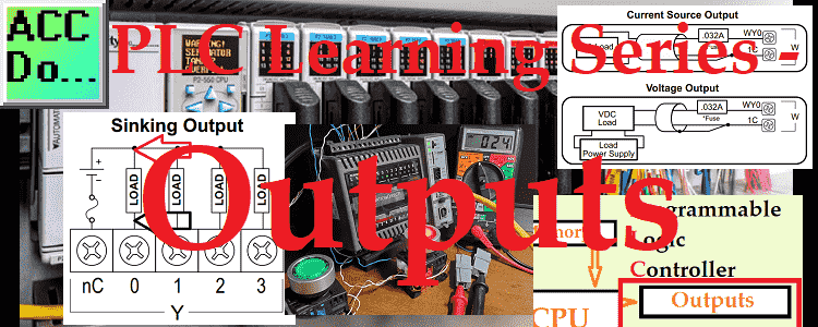
PLC Training Series - Tutorial for Everyone

Invented in 1968 by Dick Morley, the programmable logic controller (PLC) is a simple rugged industrial computer. This free plc training series is designed for everyone to learn about these controllers. PLCs are constantly evolving and continue to be the best option for a variety of industrial automation applications. Even though the PLC is changing, … Read more