A stack light is a valuable tool for displaying the status of a machine or process. This is used to draw the operator’s attention to the operation or condition of the machine. It is usually a vertical tower of colored lights programmed to turn on or off in various combinations to indicate different conditions. For example, a green light may indicate that a machine is operating, while a red light may indicate that it is not running. In addition to the lights, a stack light may include a horn or buzzer to provide audible feedback.
To use a stack light with a programmable logic controller (PLC), you need to wire it to the outputs of the PLC and program the controller to control the light. This article will discuss the five-step best practices for testing and wiring a stack light to a PLC and programming it for optimal performance.
Step 1: Choose the Right Stack Light
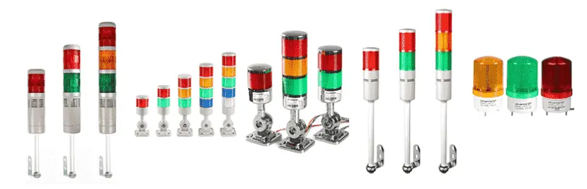
Before testing and wiring a stack light to a PLC, you must choose the right one for your application. Stack lights come in different sizes, shapes, and colors, and some models include a horn or buzzer. Consider the following factors when selecting the right stack light:
– The number of lights: Stack lights can have two, three, four, or more lights. Choose the number of lights based on the conditions you need to display.
– The colors of the lights: Stack lights can have red, green, yellow, blue, or white lights. Choose the colors based on the conditions you need to display. For example, green may indicate that a machine is operating, while red may indicate that it is not running.
– The size and shape of the stack light: Stack lights come in different sizes and shapes. Choose the size and shape that will fit your application. This is usually determined by the visibility of the light at a distance. Manufacturers typically add more LED lights to increase visibility.
– The voltage and current rating of the stack light: Stack lights are available in different voltage and current ratings. Choose the voltage and current rating that matches the output of your PLC.
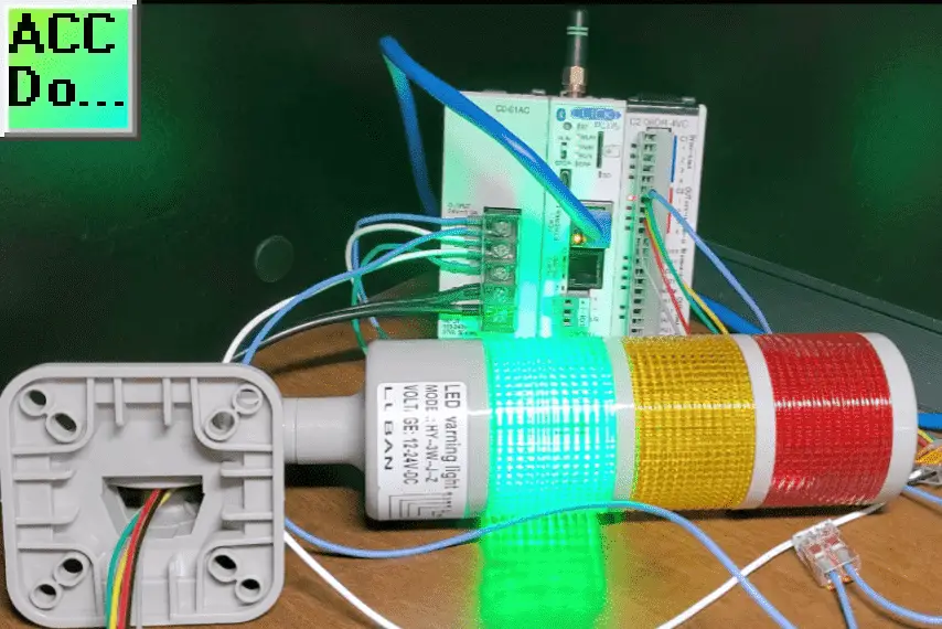
In our case, we are using a model HY-3W-HZ stack light.
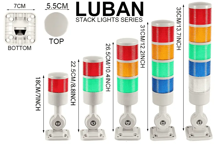
This has three lights, and a buzzer, and is powered from a 12-24 volt DC supply. They are available through Amazon.
Step 2: Testing the Stack Light
Getting new equipment is always exciting. Always read the instructions and review the wiring diagram of any equipment before wiring the device.
Our stack light is a model HY-3W-HZ. The supply voltage is 12 – 24VDC.
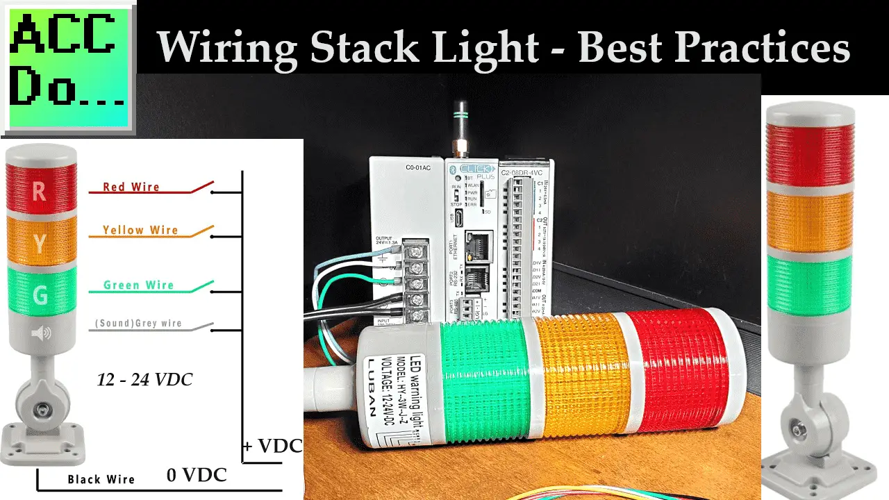
Looking at the wiring diagram, we will connect the 0VDC to the black wire of the stack light.
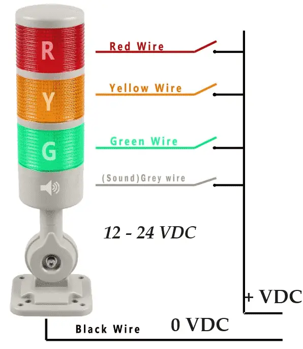
We can test each light by connecting the corresponding wire to the +VDC. In our case, this is 24 Volts DC.
Our stack light has a switch on each light to allow the light to flash automatically if the output is on.
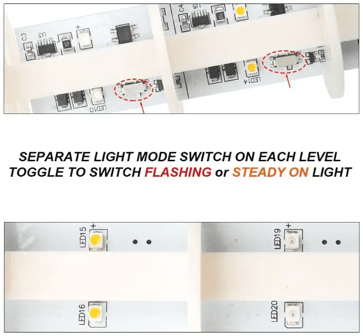
This will save you from programming this feature in the PLC or circuit. Twist the base to remove the lens of the lights. Turn on the switch for the corresponding light color. You will now see the light will flash when we test the light.
See the video below on the testing of the stack light.
We will keep the light on steady, which is the default. Replace the lens cover of the stack light.
Step 3: Wire the Stack Light to the PLC
Once you have selected and tested the right stack light for your application, you need to wire it to an output of the PLC. We will use four relay outputs on the Click PLC to control the stack light. Follow these steps to wire the stack light to the PLC:
1. Turn off the power to the machine or process.
2. Identify outputs on the PLC that you will use to control the stack light.
3. Connect the positive (+) terminal of the power supply to the output common of the PLC.
4. Connect the negative (-) terminal (Black) of the stack light to the common terminal (0 Volts DC) of the power supply. This was previously done during our testing.
5. Connect the Green, Yellow, Red, and Horn wires to the output terminals of the PLC. Our PLC output relays will now complete the circuit if activated to the + Voltage DC, turning the stack light on.
6. We can now turn on the power to the machine or process.
Step 4: Test the PLC outputs to Control the Stack Light
After wiring the stack light to the PLC outputs, we will test this to ensure the wiring is correct. This step should be done before programming or running the PLC program. It is often referred to as wringing out the IO.
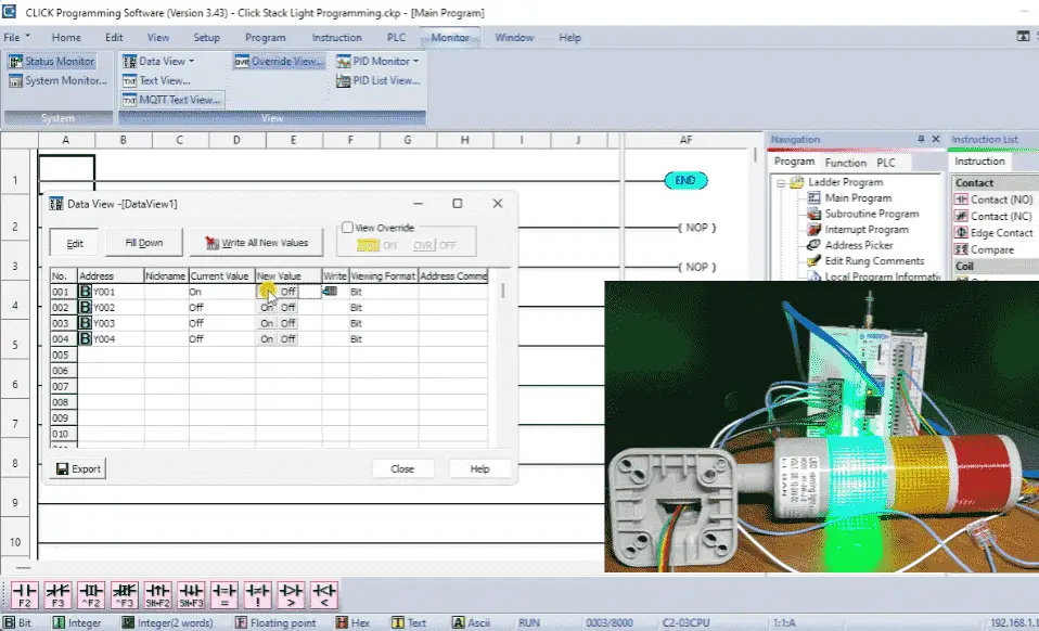
Call up the data view window of the PLC. You will see that we currently only have an END statement in our program. Enter the PLC outputs that we have wired to the PLC. Select the on and off of the outputs to see if we have wired this correctly.
See the video below to watch this in operation.
Step 5: Program the PLC to Control the Stack Light
We can now program the controller to control the light. When programming a stack light, it is recommended that you have a way to test the functionality. This can be a physical button selected to turn on all the lights and sound, or in our case, when the PLC first powers on. This ensures the stack light is functioning correctly and does not need repair.
Follow these best practices when programming the stack light:
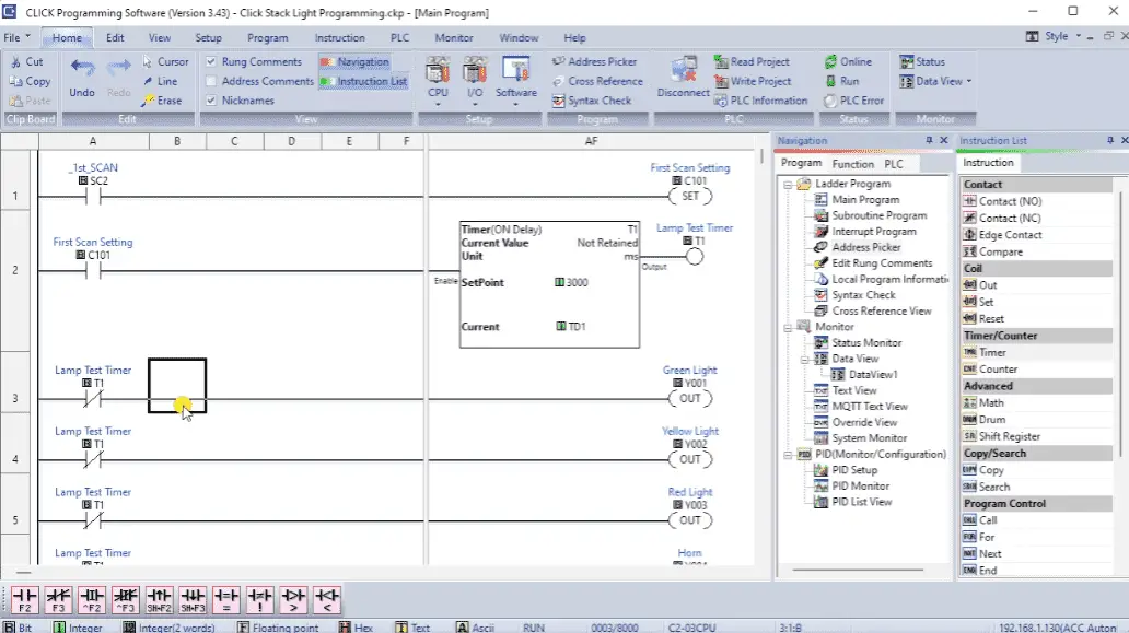
1. Use a ladder logic diagram to program the stack light. A ladder logic diagram is a graphical representation of the control logic that uses symbols to represent the control system’s inputs, outputs, and functions.
2. Use a separate rung of the ladder logic diagram for each light and horn of the stack light. This will make the program easier to understand and modify.
3. Use descriptive names for the control system’s inputs, outputs, and functions. This will make the program easier to understand and modify.
4. Use timers and counters to control the duration and frequency of the lights and horn. For example, you may want the green light to blink every 10 seconds to indicate that a machine is in operation.
5. Use fault detection and alarm functions to detect and respond to faults in the machine or process. For example, you may want the red light to turn on and the horn to sound if a machine is overheating.
A stack light is an available tool for displaying the status of a machine or process. To use a stack light with a programmable logic controller (PLC), you need to wire it to an output of the PLC and program the controller to control the light. Follow the best practices discussed in this article to ensure that the stack light works as intended and provides accurate and reliable feedback to the operator.
Download the Click PLC program here for the stack light operation.
Watch on YouTube: Wiring a Stack Light to a PLC: Best Practices
PLC Beginner’s Guide to PLC Programming
There are many different PLC manufacturers with other hardware and software. All of the programmable logic controllers have similar basic features. Here is how I would approach learning about basic PLCs.
Once you are familiar with the basics of the PLC, you will then learn specifics for the controller you will be programming.
This is the easiest way to learn about PLC programming.
Here are the controllers that we have covered or are covering at ACC Automation:
Arduino Opta PLC
BRX Do-More Series (Do-More Designer Software + Simulator)
Productivity Series P1000 / P2000
Click PLC Series
Omron CP1H Series
Horner XL4 PLC Series
EasyPLC Software Suite is a complete PLC, HMI, and Machine Simulator Software package. See below to receive 10% off this software. This PLC learning package includes the following:
Easy PLC – PLC Simulation will allow programming in Ladder, Grafcet, Logic Blocks, or Script.
HMI System – Easily create a visual human-machine interface (HMI)
Machine Simulator – A virtual 3D world with real-time graphics and physical properties. PLC programs can be tested using the EasyPLC or through other interfaces. (Modbus RTU, TCP, etc.)
Machine Simulator Lite – Designed to run on Android Devices.
Machine Simulator VR – Virtual Reality comes to life so you can test, train, or practice your PLC programming.
Purchase your copy of this learning package for less than $95 USD for a single computer install or less than $110 USD to allow different computers.
Receive 10% off the investment by typing in ACC in the comment section when you order.
Learn PLC programming the easy way. Invest in yourself today.
Additional examples of PLC program development using the five steps.
Click PLC – Easy Transfer Line Programming – Video
Productivity PLC Simulator – Chain Conveyor MS – Video
Five Steps to PLC Program Development – Die Stamping
PLC Programming Example – Process Mixer
PLC Programming Example – Shift Register (Conveyor Reject)
PLC Programming Example – Paint Spraying
PLC Programming Example – Delay Starting of 7 Motors
PLC Programming Example – Pick and Place
PLC Programming Example – Sorting Station (Shift Register)
PLC Programming Example – Palletizer
If you have any questions or need further information, please contact me.
Thank you,
Garry
If you’re like most of my readers, you’re committed to learning about technology. Numbering systems used in PLCs are not challenging to learn and understand. We will walk through the numbering systems used in PLCs. This includes Bits, Decimals, Hexadecimal, ASCII, and Floating Points.
To get this free article, subscribe to my free email newsletter.
Use the information to inform other people how numbering systems work. Sign up now.

The ‘Robust Data Logging for Free’ eBook is also available as a free download. The link is included when you subscribe to ACC Automation.