Data logging does not have to be complicated anymore. The BRX Do-More Series PLC can log your specific data up to 32 Gigabits on a Micro SD Card. It will store your data for future data analysis in a CSV (Comma Separated Value) Txt file based on time and/or event.
This is all accomplished with just one instruction in the BRX PLC. Excel is just one program that you can import and analyze this CSV Text file.
Do-More Designer has a Browse PLC File Systems window that will allow you to copy, create and delete the files from the connected computer. This will save you from going to each controller, removing and copying the files on the Micro SD Card.
We will be looking at the data logging instruction in the BRX Series PLC and how to retrieve and view this information. Let’s get started.
Previously in this BRX Do-More series PLC, we have discussed:
System Hardware – Video
Unboxing – Video
Installing the Software – Video
Establishing Communication – Video
Firmware Update – Video
Numbering Systems and Addressing – Video
First Program – Video
Monitoring and Testing the Program – Video
Online Editing and Debug Mode – Video
Timers – Video
Counters – Video
High-Speed IO – Video
Compare Instructions – Video
Math Instructions – Video
Program Control – Video
Shifting Instructions – Video
Drum Instruction – Video
Serial Communication – Modbus RTU to Solo Process Temperature Controller – Video
BRX Do-More Memory
The BRX Do-More Series PLC provides two different ways to store logged data. You can use the system RAM or the micro SD card.
The system ram is 1 MB and is available in all Do-more CPUs. (@RamFS)
A removable memory card (Micro SD) can be purchased and inserted into the CPU unit of the BRX Do-More Series PLC. This card can be up to 32GB and formatted to FAT32 before it can be used. All current speeds for memory are supported by the BRX Do-More PLC.
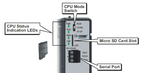
Insert microSD card with notched side down. Gently press into microSD receptacle until click is heard and felt. To remove the card, press in microSD card until click and release. The card will move out. Gently pull microSD card from slot.
A MEM light is on the CPU next to the miroSD slot and is for the memory card. Here are the following colour meanings for the light:
OFF – No ROM activity, No SD card
Yellow – ROM activity (Flash or SD card)
Green – SD card installed and mounted
Red – SD card installed and not mounted
Note: The microSD card will become mounted when the PLC (MPU) multi-processor unit recognizes and renders it accessible for use.
The BRX Do-More Series PLC has several different instructions for the File System. This will allow you open, close, read, write and perform file system commands. There is even an instruction to create a PLC image file for backups of the system. We will be focusing on the FILELOG – Log to file instruction.
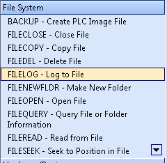
FILELOG Instruction – BRX Do-More
The FILELOG instruction will automatically store our specified data by creating, opening, appending, and closing files for us on the BRX Do-More PLC. We indicate the parameters and this instruction will take over. Here are the parameters of the instruction:

File System – @RamFS – on board 1 MB file system in all Do-more CPUs. @SDCardFS – Removable media installed in the micro-SD card slot on the BRX Do-More only.
Base .CSV File Name – This is the name of the file that will be stored.
Append Timestamp to File Name – This is a selection that will help ensure that all of the file names used will be unique. New information will not get over written.
Input Leg – This will be either edge triggered (log on event) or power flow enabled (time based log event)
Generate File Name – This option will place the name of the file in a character string within the memory of the PLC.
List of Element to Log – This is where we specify the information that will be logged each time the instruction executes. The list can be 50 entries maximum. You can specify an element or range of elements. The maximum size for the log entry is 1024 bytes.
Note: A time stamp is already included in each entry.
On Success bit – This bit will turn on when the instruction has logged and entry successfully
On Error bit – This bit will turn on when the instruction execution is unsuccessful.
Timed FILELOG Instruction – BRX Do-More
Let’s look at an example of a timed FILELOG instruction.
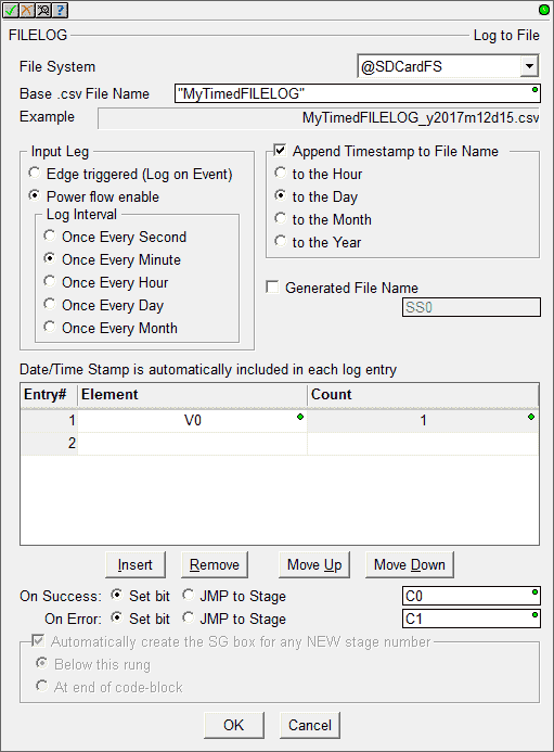
In our example, we will be writing to the microSD card. (@SDCardFS) The name of the CSV file will be “MyTimedFILELOG” with the date added. We will set this to log once every minute.
Our logged information will come from V0. We will be logging just the one register. C0 and C1 will be set upon the success and error of the instruction execution.
Here is the ladder logic.
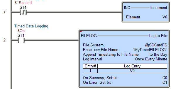
You will notice that V0 will increment every time the $1 second system pulse bit turns on. The File Log instruction will be always on using the system bit. Since we set the logging every minute we should see in our log file the value in V0 60 seconds apart.
Event FILELOG Instruction – BRX Do-More
Here is an example of an event FILELOG instruction.
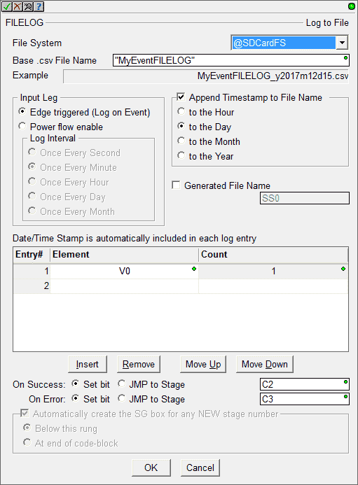
In our example, we will be writing to the microSD card. (@SDCardFS) The name of the CSV file will be “MyEventFILELOG” with the date added. This is logged every time the instruction is executed.
Our logged information will come from V0. We will be logging just the one register. C2 and C3 will be set upon the success and error of the instruction execution.
Here is the ladder logic.
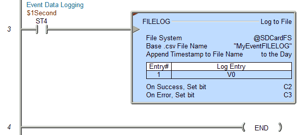
We are executing this LOGFILE instruction by the system 1 second clock bit pulse. This means that we should see the value in our logged information be incremented by one every entry.
We can now go online, download and run the program. You will notice that the MEM light on the CPU will turn orange every time information is being written to the Micro SD card. Once we are online, we can then see the files that we are logging by using the “Browse PLC File Systems…”
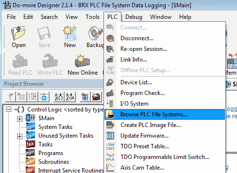
Main Menu | PLC| Browse PLC File Systems…
The Browse PLC File Systems window will now appear.
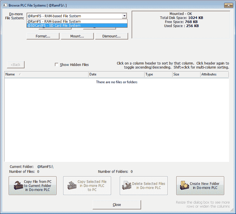
Select the @SDCardFS – SD Card File System
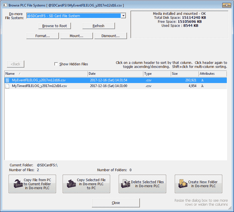
We now see our two files that are being logged. Notice that the format of the file is the same as we expected with the name followed by the date.
Retrieving the logged files from the BRX Do-More SD Card to the PC
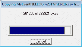
Double-clicking the file or selecting “Copy Selected File in Do-more PLC to PC” will display the following information for saving.
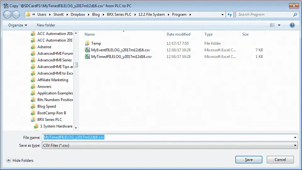
Hit Save.
Do the same for both of the files that we have logged.
We can now call up the files using Excel or any other program that will read a CSV file.
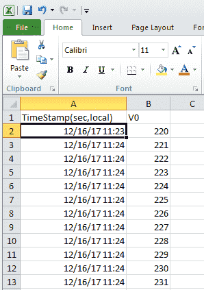
Here is the event-driven file. You will notice that the numbers increment by one every second.
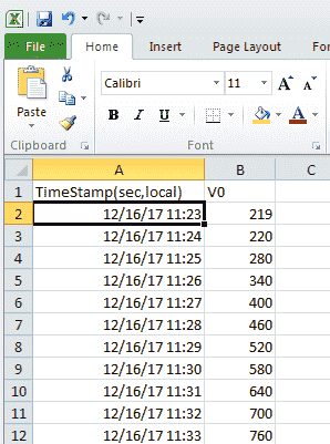
Here is the time based file. There is a difference of 60 between the numbers. This is because we have set up the time for 1 minute updates.
Setting up data logging in the BRX Do-More Series PLC is very straight forward. One instruction is all we need to accomplish our data collection. You can watch the video below to see this data logging in the BRX Do-More Series PLC.
You can download the program here.
BRX Do-More Series PLC from Automation Direct – Power to deliver
Overview Link (Configure and purchase a system)
Manuals and Product Inserts (Installation and Setup Instruction)
Do-More Designer Software v2.0.3 (Free Download Link) – The software will contain all of the instruction sets and help files for the BRX Series PLC.
Next time we will look at sending emails with file attachments in the BRX Do-More PLC.
Watch on YouTube : BRX PLC Data Logging
If you have any questions or need further information please contact me.
Thank you,
Garry
If you’re like most of my readers, you’re committed to learning about technology. Numbering systems used in PLC’s are not difficult to learn and understand. We will walk through the numbering systems used in PLCs. This includes Bits, Decimal, Hexadecimal, ASCII and Floating Point.
To get this free article, subscribe to my free email newsletter.
Use the information to inform other people how numbering systems work. Sign up now.

The ‘Robust Data Logging for Free’ eBook is also available as a free download. The link is included when you subscribe to ACC Automation.