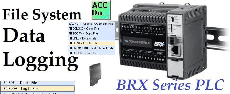
Data logging does not have to be complicated anymore. The BRX Series PLC can log your specific data up to 32 Gigabits on a Micro SD Card. It will store your data for future data analysis in a CSV (Comma Separated Value) Txt file based on time and/or event.
This is all accomplished with just one instruction in the BRX PLC. Excel is just one program that you can import and analysis this CSV Text file.
Do-More Designer has a Browse PLC File Systems window that will allow you to copy, create and delete the files from the connected computer. This will save you from going to each controller, removing and copying the files on the Micro SD Card.
We will be looking at the data logging instruction in the BRX Series PLC and how to retrieve and view this information. Let’s get started. Continue Reading!
Tag Archives: excel
Excel Conditional Movement of Data
I have been recently asked how you can move data conditionally on an excel spreadsheet once the information has been obtained from the PLC? Monthly data was being collected from the PLC and put on an excel spreadsheet using Omron CX-Server DDE. They wanted at the beginning of each month to move the data to the appropriate month so they can track the changes.
The following three blogs were posted on how to get data into the Microsoft Excel Spreadsheet from the programmable logic controller. (PLC)
HOW TO IMPLEMENT MODBUS TCP PROTOCOL USING VBA WITH EXCEL
IMPLEMENTING THE OMRON CX SERVER DDE AND EXCEL
HOW TO IMPLEMENT THE OMRON HOST LINK PROTOCOL PART 2 – VBA
The method to move the data around the spreadsheet once the data has been obtained will be done by Visual Basic for Applications. (VBA)
Make a spreadsheet in excel as follows:
Operation:
When the current data in A2 or B2 changes, it will trigger a macro to execute. This macro will use the Worksheet_Change to trigger the code. The date in A2 is then compared to all of the dates located from A5 to A30. If a match is found then the value in B2 is placed beside the matching date found column. Example: A2 = A7 then B7 = B2
Here is a look at the VBA editor and code:
Here is the following code:
Private Sub Worksheet_Change(ByVal Target As Range)
If Target.Address = “$A$2” Or Target.Address = “$B$2” Then
For x = 5 To 30
If Sheets(“Sheet1”).Range(“A2”) = Sheets(“Sheet1”).Range(“A” & x) Then
Sheets(“Sheet1”).Range(“B” & x) = Sheets(“Sheet1”).Range(“B2”)
End If
Next ‘x
End If
End Sub
Download the example excel file.
Watch on YouTube : Excel Conditional Movement of Data
If you have any questions or need further information please contact me.
Thank you,
Garry
If you’re like most of my readers, you’re committed to learning about technology. Numbering systems used in PLC’s are not difficult to learn and understand. We will walk through the numbering systems used in PLCs. This includes Bits, Decimal, Hexadecimal, ASCII and Floating Point.
To get this free article, subscribe to my free email newsletter.
Use the information to inform other people how numbering systems work. Sign up now.
The ‘Robust Data Logging for Free’ eBook is also available as a free download. The link is included when you subscribe to ACC Automation.
How to Implement Modbus TCP Protocol using VBA with Excel
We will use Visual Basic for Applications (VBA) to communicate to a PLC using Modbus TCP protocol. Reading ten registers in the PLC and displaying a bar graph in Excel. Previously we have used VB6 to communicate Modbus TCP.
The following steps will be done:
- Explain Modbus TCP protocol
- Install OstroSoft Winsock Component
– Winsock API Calls for communication on network - Develop the Excel and VBA application
(Microsoft Excel 2010) - Communicate to the PLC and sample code
(Do-More Simulator)
The Modbus TCP/IP or Modbus TCP is a Protocol that is used for communications over TCP/IP networks. This is done on port 502. Modbus TCP does not require a checksum calculation as lower layers already provide checksum protection. You can think of this as a letter being sent and Ethernet TCP/IP acts like an envelope for the Modbus Commands. I will not go into the details of the communication protocol but here are some links to references:
Introduction to Modbus TCP/IP
Simply Modbus – Modbus TCP
OstroSoft Winsock Component
OSWINSCK.dll serves as a wrapper for the Winsock API and helps programmers to abstract from the complexity of API calls and focus on application functionality. Works with programming and scripting languages supporting COM.
You will need to download and install the OstroSoft Winsock Component on your computer.
For use with .NET, Visual Basic 4 or 5, Visual C++, ASP, VBA, VBScript, JavaScript or any other language, supporting COM:
1. Download oswinsck.exe
2. Run downloaded file from Windows Explorer or command-line
Hit OK
I use the default directories where the program will be installed. Click the button to install.
Leave the program group to the default so I know what the program is after installation. Click continue.
Click OK
The OstroSoft Winsock Component is now installed.
Start Microsoft Excel.
Select ‘Developer’ along the top tabs.
If the Developer tab is not present then we must turn on the developer tab.
Select File | Options Select ‘Customize Ribbon’
Check the ‘Developer’ under Main Tabs.
Under the Developer menu. Select ‘Visual Basic’
The Visual Basic Editor window will now be displayed.
From the menu – Tools | References
We can now add the OstroSoft Winsock Component to our application.
Select OK
Select Sheet1(Sheet1).
Now put the visual basic code in the Sheet1(Sheet1)
Here is the code:
‘This example uses OstroSoft Winsock Component
‘http://www.ostrosoft.com/oswinsck.asp
Option Explicit
Dim bytesTotal As Long
Dim sPage As String
Dim MbusQuery
Dim returnInfo
Dim wsTCPgdb
Dim WithEvents wsTCP As OSWINSCK.Winsock
Dim SetObject
Dim RetrieveData
Private Sub CommandButton1_Click() ‘ Retrieve Data
On Error GoTo ErrHandler
Dim sServer As String
Dim nPort As Long
Dim StartTime
DoEvents
nPort = 502 ‘ See configuration in Do-More Designer
‘ Set the IP address of the PLC
sServer = Sheets(“Sheet1”).Range(“B4″) ‘”192.168.1.3”
RetrieveData = 1
CommandButton1.BackColor = “&H0000FF00” ‘ Set colour to Green
‘Check to see if the object has been created. If not set wsTCP.
If SetObject = “” Then
Set wsTCP = CreateObject(“OSWINSCK.Winsock”)
wsTCP.Protocol = sckTCPProtocol
SetObject = 1
End If
‘ Check the state of the TCP connection
‘0 sckClosed connection closed
‘1 sckOpen open
‘2 sckListening listening for incoming connections
‘3 sckConnectionPending connection pending
‘4 sckResolvingHost resolving remote host name
‘5 sckHostResolved remote host name successfully resolved
‘6 sckConnecting connecting to remote host
‘7 sckConnected connected to remote host
‘8 sckClosing Connection Is closing
‘9 sckError error occured
‘ If TCP is not connected, try to connect again.
If wsTCP.State <> 7 Then
If (wsTCP.State <> sckClosed) Then
wsTCP.CloseWinsock
End If
‘ Open the connection
wsTCP.Connect sServer, nPort
StartTime = Timer ‘ Use the timer to determine if a connection cannot be made
Do While ((Timer < StartTime + 2) And (wsTCP.State <> 7))
DoEvents
Loop
If (wsTCP.State = 7) Then
Else
Exit Sub
End If
End If
‘ If we are connected then request the information.
If (wsTCP.State = 7) Then
MbusQuery = Chr(0) + Chr(0) + Chr(0) + Chr(0) + Chr(0) + Chr(6) + Chr(0) + Chr(3) + Chr(0) + Chr(0) + Chr(0) + Chr(20)
wsTCP.SendData MbusQuery ‘Send out the Modbus Information
‘ Read the information
‘0000: Transaction Identifier
‘0000: Protocol Identifier
‘0006: Message Length (6 bytes to follow)
’00: The Unit Identifier
’03: The Function Code (read MHR Read Holding Registers)
‘0000: The Data Address of the first register
‘0002: The number of registers to write
‘ Write the information
‘0000: Transaction Identifier
‘0000: Protocol Identifier
‘0009: Message Length (6 bytes to follow)
’01: The Unit Identifier
’16: The Function Code (read Analog Output Holding Registers)
‘0000: The Data Address of the first register
‘0001: The number of registers to write
’02: The number of data bytes to follow
‘0030 The number to put into the register
‘ Note: Addresses are offset by 1
‘ Example: MHR1 = Address 0000
‘ Example: MHR30 = Address 0029
End If
Exit Sub
ErrHandler:
MsgBox “Error ” & Err.Number & “: ” & Err.Description
End Sub
Private Sub CommandButton2_Click() ‘ Stop the communication
RetrieveData = 0
CommandButton1.BackColor = “&H8000000F” ‘ Set the default colour
End Sub
Private Sub wsTCP_OnDataArrival(ByVal bytesTotal As Long)
Dim sBuffer
Dim i
Dim MbusByteArray(500)
Dim h As Integer
Dim txtSource
wsTCP.GetData sBuffer
txtSource = txtSource & sBuffer
Dim j As Byte
returnInfo = “”
For i = 1 To bytesTotal
wsTCP.GetData j, vbByte
MbusByteArray(i) = Asc(Mid(sBuffer, i, 2))
returnInfo = returnInfo & Asc(Mid(sBuffer, i, 2))
Next
txtSource = returnInfo
txtSource = Val(Str((MbusByteArray(10) * 256) + MbusByteArray(11)))
Sheets(“Sheet1”).Range(“B10”) = Val(Str((MbusByteArray(10) * 256) + MbusByteArray(11)))
Sheets(“Sheet1”).Range(“B11”) = Val(Str((MbusByteArray(12) * 256) + MbusByteArray(13)))
Sheets(“Sheet1”).Range(“B12”) = Val(Str((MbusByteArray(14) * 256) + MbusByteArray(15)))
Sheets(“Sheet1”).Range(“B13”) = Val(Str((MbusByteArray(16) * 256) + MbusByteArray(17)))
Sheets(“Sheet1”).Range(“B14”) = Val(Str((MbusByteArray(18) * 256) + MbusByteArray(19)))
Sheets(“Sheet1”).Range(“B15”) = Val(Str((MbusByteArray(20) * 256) + MbusByteArray(21)))
Sheets(“Sheet1”).Range(“B16”) = Val(Str((MbusByteArray(22) * 256) + MbusByteArray(23)))
Sheets(“Sheet1”).Range(“B17”) = Val(Str((MbusByteArray(24) * 256) + MbusByteArray(25)))
Sheets(“Sheet1”).Range(“B18”) = Val(Str((MbusByteArray(26) * 256) + MbusByteArray(27)))
Sheets(“Sheet1”).Range(“B19”) = Val(Str((MbusByteArray(28) * 256) + MbusByteArray(29)))
DoEvents
‘ Determine if we retrieve the data again.
If RetrieveData = 1 Then
Call CommandButton1_Click
End If
End Sub
Private Sub wsTCP_OnError(ByVal Number As Integer, Description As String, ByVal Scode As Long, ByVal Source As String, ByVal HelpFile As String, ByVal HelpContext As Long, CancelDisplay As Boolean)
MsgBox Number & “: ” & Description
End Sub
Private Sub wsTCP_OnStatusChanged(ByVal Status As String)
Debug.Print Status
End Sub
Note: The program utilizes the CHR and STR functions to convert the data from binary to ASCII and back.
The highest value of a byte of data is 256. This is why we have to multiply the highest significant byte with 256
Interface:
Go back to Sheet1 and we can now put on the worksheet what we would like to see.
Note the following:
IP Address = B4
MHR 1 to 10 values located at B10 to B19
‘Stop Data’ – CommandButton2
‘Retrieve Data’ – CommandButton1
Communication to the PLC
Start the Do-More Designer software.
Under the Project Browser select ‘System Configuration’
Make note of the IP address. If you are running the simulator then this is automatically filled in.
Ensure that the Enable Modbus/TCP Server is checked. Also make sure that the TCP Port Number is 502.
The sample PLC program will write values in the range from 0 to 4000. These values will be put in MHR 1 to MHR 10.
Here is the first couple of rungs of the PLC program. It will use clock bit flags to increment the MHR 1 channel. When it gets to the value above 4000, a move instruction will put a 0 back into MHR 1.
If input X0 turns on then the value in XW0 will be moved into MHR1 and the previous clock bit will not be in effect. Values will be between 0 and 4096. (12 bit resolution)
This is repeated with different internal clock bit flags up to MHR10.
Running the program will produce the following:
As you can see the Modbus TCP protocol is easy to implement with visual basic for applications.
Download the PLC program and Excel file.
Additional Information:
Excel – Conditional Movement of Data
Watch on YouTube : How to Implement Modbus TCP Protocol using VBA with Excel
If you have any questions or need further information please contact me.
Thank you,
Garry
If you’re like most of my readers, you’re committed to learning about technology. Numbering systems used in PLC’s are not difficult to learn and understand. We will walk through the numbering systems used in PLCs. This includes Bits, Decimal, Hexadecimal, ASCII and Floating Point.
To get this free article, subscribe to my free email newsletter.
Use the information to inform other people how numbering systems work. Sign up now.
The ‘Robust Data Logging for Free’ eBook is also available as a free download. The link is included when you subscribe to ACC Automation.
Implementing the Omron CX Server DDE and Excel
Utilizing the CX Server DDE Manager will allow us to provide a link to the information in the Omron PLC. This link can be placed on an Excel spreadsheet. Charts, graphs, etc. can be made from the data. We will create links on an excel spread sheet from a CQM1H and a CP1L PLC. The information will then be displayed as a bar graph comparing the first ten memory areas.
Dynamic Data Exchange (DDE) is a channel through which correctly prepared programs can actively exchange data and control other applications within Microsoft Windows. The DDE manager will allow us to set up all of the links.
Start the DDE Manager by clicking Start/Programs/Omron/CX-Server/DDE Manager
This will start the DDE Manager and place an icon on your toolbar at the bottom of your screen. The application will run minimized.
Right-click on the minimized DDE Manager icon and select Project/New.
Assign a filename (ACC DDE.cdm) to the CX-Server project that you will create, and save it.
The create project will minimize to the taskbar. Right-click on the minimized DDE Manager icon and select Project/Edit.
This will call up the DDE Manager Project Editor. We can now add the PLC’s (Devices) and Points that we want to display.
Select File/New/PLC, or hit the PLC Icon on the taskbar.
Under Change PLC, we can now enter the information about how we are communicating to the programmable logic controller.
Device Name: – Name in which the DDE Manager will call the PLC
Device Type: – The model of PLC that will be connected
Network Type: – This is the communication method that we will be talking with the device.
In our example we will use the following two Omron PLCs.
- CQM1H – SYSMAC WAY (Omron Host Link Protocol) Communication Port 11, 9600, E, 7, 2. Unit #00
- CP1L – USB
Once we have the PLC information, we can now add points that will contain the information that we wish to retrieve from the units. Select File/New/Point or select the point editor icon to start the point editor.
On the Logical tab you can give a name (Or Change) to the point in the PLC to get. Select the Physical tab.
On the physical tab we set the following information:
PLC: – This is the list of PLCs entered in the previous step
Data Location: – The memory location that we want to read from
Internal Data Type: – This is the interpretation of the data that we are reading. (Example: Bit, Word, BCD, etc.)
Command Modifier: – This is used if we need to Force Set / Reset the data location. This can be used to override the PLC program. Use with caution.
Press OK when finished setting the address.
Our point is now programmed. You will notice the symbols before the name of the point. This tells us at a quick glance what type of data we are looking at. Please refer to the CX Server Runtime manual for all of the symbol meanings.
Fill out the remaining points for our example.
CP1L – D0 to D9
CQM1H – DM0 to DM9
Go back to the DDE manager and the points under the Project Editor. We can now select the first ten items in the list. Click the first one and then move to the last item. Hold the shift while clicking the last item will select all of them between.
Hit the DDE Link icon.
In Excel, we now paste the information onto the worksheet. (Ctrl + V) Right click the cell and select paste.
The information will now be displayed and updated on your worksheet.
The update time will depend on the interval set in the DDE Manager. Right-click on the minimized DDE Manager icon and select Update Interval…
We can also set individual point update times in the DDE link item. The default update time is set via the DDE Manager but we can also set the time in the individual points on the spreadsheet.
DDE Update Default Link:
=CDMDDE|’C:\ACC DDE.cdm’!’\CP1L D0′
5 Second Update Link:
=CDMDDE|’C:\ACC DDE.cdm’!’\CP1L D0,5′
In the Project Editor of the DDE Manager you can see the first 10 memory areas are being used. This is the yellow triangle with the lightning bolt symbol. (You will not be able to delete the point if it is in use.)
Calling up an excel file with the links embedded, will give you a Security Alert – Links warning. Select ‘Enable the content’ and then hit OK.
Here is an example of the finished excel file. We have 10 memory locations from each PLC listed. We have inserted a graph that will dynamically change when the values are read.
Download the excel file here.
As you can see implementing the CX Server DDE Manager is not a difficult task. It provide a quick and efficient way to view the information that we need.
Additional Information:
Excel – Conditional Movement of Data
Watch on YouTube : Implementing the Omron CX Server DDE and Excel
If you have any questions or need further information please contact me.
Thank you,
Garry
If you’re like most of my readers, you’re committed to learning about technology. Numbering systems used in PLC’s are not difficult to learn and understand. We will walk through the numbering systems used in PLCs. This includes Bits, Decimal, Hexadecimal, ASCII and Floating Point.
To get this free article, subscribe to my free email newsletter.
Use the information to inform other people how numbering systems work. Sign up now.
The ‘Robust Data Logging for Free’ eBook is also available as a free download. The link is included when you subscribe to ACC Automation.
How to Implement the Omron Host Link Protocol Part 2 – VBA
ACC Omron Host Link VBA
In Part 1, we used VB6 to communicate from the computer to the PLC. We will now use Visual Basic for Applications (VBA) to accomplish the same task. NETComm will be the serial driver and Excel will be the program that we will use. Using Excel we will have access to the Excel Object Model so we can utilize worksheets, ranges etc.
Please refer to Part 1 (How to Implement the Omron PLC Host Link Protocol) for the details of the wiring of the serial port and protocol sequence.
The first step in using VBA is to download and register NETComm.ocx. To use serial communications with VBA you must register the NETComm.ocx driver.
Download the NETComm.ocx file to the c:\ directory.
Call up a dos prompt with administrator authority. (Right click on the cmd.exe program and select run as administrator.)
An information box will be shown indicating that the NETComm.ocx was registered successfully.
Now open Excel and make the following on Sheet 1.
Select Developer and then Visual Basic.
If you do not have the Developer option to select, then do the following:
Select File : Options: Customized Ribbon
Select Developer and hit OK
VBA – Visual Basic for Applications will open
Add NETComm1 to UserForm1. If it is not on your Toolbar, then select additional controls and select NETCommOCX.NETComm. Press the OK. Then drag this control onto your form.
Create three command buttons. This can be done by going to Design Mode, and under the Insert menu you can select Command Buttons.
Here is the entire code for the application:
Private T$ ' Modual Scope for variable Private TRead$ Private NumWords Private startcycle
Private Sub CommandButton1_Click() If NumWords = "" Then MsgBox "Set Read String" Exit Sub End If If startcycle = 0 Then startcycle = 1 CommandButton1.BackColor = "&H0000FF00" Else startcycle = 0 CommandButton1.BackColor = "&H8000000F" UserForm1.NETComm1.PortOpen = False ' Close Communication Port Exit Sub End If UserForm1.NETComm1.PortOpen = True ' Open Communication Port Application.EnableEvents = True Do T$ = TRead$ ' Reset the Transmitted Information charreturn = 11 + (NumWords * 4) ' Determine the return characters GoSub FCS ' Checksum GoSub communicate ' Get informaiton 'Check returned information and Display If Mid(rxd$, 6, 2) = "00" And (Len(rxd$)) >= charreturn Then For x = 1 To Sheets("Sheet1").Range("D7") Sheets("Sheet1").Range("B" & x + 10 - 1) = Mid(rxd$, x * 4 + 4, 4) Next 'x End If
DoEvents ' Do other tasks 'Update the date and time Sheets("Sheet1").Range("C09") = Format(Date, "YYYY/MM/DD") + " " + Format(Time, "HH:MM:SS") Loop While startcycle = 1
If startcycle = 0 Then Exit Sub
communicate: rxd$ = "" Buffer = T$ + FCS$ + "*" + Chr$(13) UserForm1.NETComm1.Output = Buffer Time1 = Now Timeout = Now + TimeValue("0:00:02") Do If Timeout <= Time1 Then GoTo timeoutcom DoEvents Time1 = Now() Loop Until UserForm1.NETComm1.InBufferCount >= charreturn rxd$ = UserForm1.NETComm1.InputData fcs_rxd$ = Left((Right(rxd$, 4)), 2) If Left(rxd$, 1) = "@" Then T$ = Mid(rxd$, 1, (Len(rxd$) - 4)) ElseIf Mid(rxd$, 2, 1) = "@" Then T$ = Mid(rxd$, 2, (Len(rxd$) - 5)) rxd$ = Mid(rxd$, 2, (Len(rxd$) - 1)) End If GoSub FCS If FCS <> fcs_rxd$ Then rxd$ = "" End If clearbuffer$ = UserForm1.NETComm1.InputData Return
FCS: L = Len(T$) A = 0 For J = 1 To L TJ$ = Mid$(T$, J, 1) A = Asc(TJ$) Xor A Next J FCS$ = Hex$(A) If Len(FCS$) = 1 Then FCS$ = "0" + FCS$ Return
timeoutcom: If startcycle = 0 Then Exit Sub clearbuffer$ = UserForm1.NETComm1.InputData rxd$ = "" Return
End Sub
Private Sub CommandButton2_Click() If startcycle = 0 Then UserForm1.NETComm1.CommPort = Sheets("Sheet1").Range("A4") UserForm1.NETComm1.Settings = Sheets("Sheet1").Range("B4") & "," & Sheets("Sheet1").Range("C4") & "," & Sheets("Sheet1").Range("D4") & "," & Sheets("Sheet1").Range("E4") MsgBox UserForm1.NETComm1.Settings Else MsgBox "Stop Reading Parameters to Set MSComm" End If End Sub
Private Sub CommandButton3_Click() If startcycle = 0 Then Unit = Sheets("Sheet1").Range("A7") If Len(Unit) < 2 Then Unit = "0" & Unit StartADD = Sheets("Sheet1").Range("C7") Do If Len(StartADD) < 4 Then StartADD = "0" & StartADD End If Loop Until Len(StartADD) = 4 NumWords = Sheets("Sheet1").Range("D7") Do If Len(NumWords) < 4 Then NumWords = "0" & NumWords End If Loop Until Len(NumWords) = 4 T$ = "@" & Unit & "RD" & StartADD & NumWords TRead$ = T$ MsgBox T$ For x = 1 To Sheets("Sheet1").Range("D7") Sheets("Sheet1").Range("A" & x + 10 - 1) = "DM " & Sheets("Sheet1").Range("C7") + x - 1 Sheets("Sheet1").Range("B" & x + 10 - 1) = "" Next 'x For x = Sheets("Sheet1").Range("D7") To 200 Sheets("Sheet1").Range("A" & x + 10) = "" Sheets("Sheet1").Range("B" & x + 10) = "" Next 'x Else MsgBox "Stop Reading Parameters to Set Read String" End If End Sub
Private Sub Worksheet_SelectionChange(ByVal Target As Range)
End Sub
Note: The Chart on Sheet1 is just a selection of the first ten DM areas and insert a bar graph.
Running the program produces the following information:
Download the excel file ACC Omron Host Link VBA.XLS. This is the complete program mentioned above.
When you open the file it will warn you about macros. This is the VBA application. Press ‘Enable Macros’.
When changing the parameters on the screen, you will also get a warning about Active X. This is the NETComm.ocx which was registered above. Press ‘OK’ to run the application.
Additional Information:
Excel – Conditional Movement of Data
Watch on YouTube : How to Implement the Omron Host Link Protocol Part 2 – VBA
If you have any questions or need further information please contact me.
Thank you,
Garry
If you’re like most of my readers, you’re committed to learning about technology. Numbering systems used in PLC’s are not difficult to learn and understand. We will walk through the numbering systems used in PLCs. This includes Bits, Decimal, Hexadecimal, ASCII and Floating Point.
To get this free article, subscribe to my free email newsletter.
Use the information to inform other people how numbering systems work. Sign up now.
The ‘Robust Data Logging for Free’ eBook is also available as a free download. The link is included when you subscribe to ACC Automation.