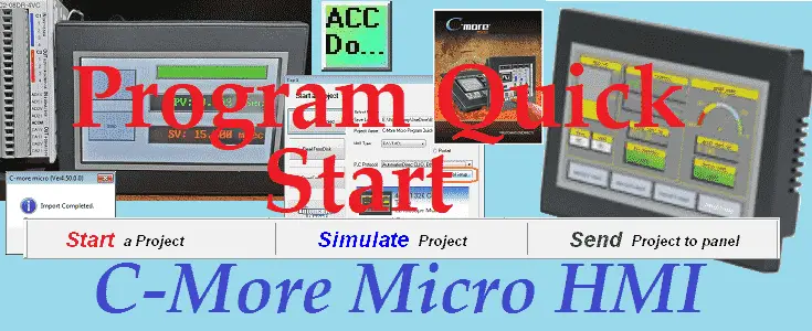
We will now look at the C-More Micro program quick start. This will demonstrate how to quickly get your C-More Micro Program up and communicating to your programmable logic controller. (PLC)
The general steps involved with a human-machine interface (HMI) program will include, program development, ladder logic, and HMI program development. We will be breaking the HMI program development into program purpose, tag import, HMI programming, simulation, and testing.
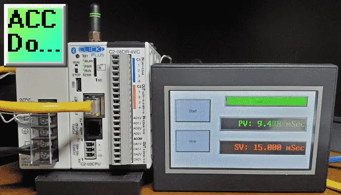
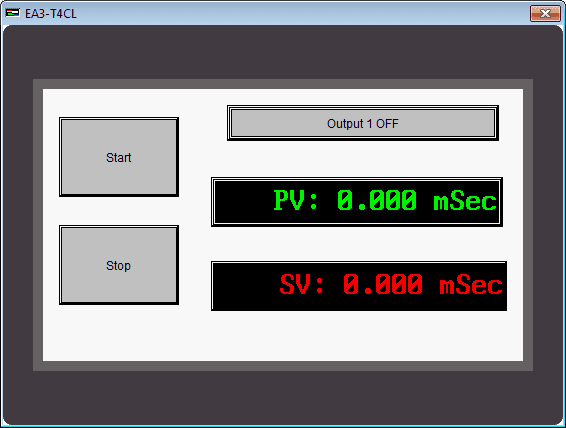
An EA3-T4CL C-More Micro HMI will be used to communicate to a Click PLC via Ethernet. A Start/Stop circuit will be programmed with a Timer. This can be controlled via the PLC inputs or HMI inputs. The timer present value (PV) will be shown on the HMI. The set value (SV) of the timer can be changed using the HMI. Let’s get started.
Previously in this C-More Micro HMI Panel series, we have done the following:
System Hardware – Video
Installing the Software – Video
– Update Automation Direct Software C-More Micro HMI Video
System Setup Screens – Video
First Program – Video
First Program Part 2 (PLC < – > Panel) – Video
Common Screen Menu – Video
Simulate Project – Video
Object List Shapes – Video
Object Buttons and Indicators – Video
Object Numeric Entry – Video
Object Meters and Graphs – Video
Object Bitmap – Video
Object Recipe – Video
Object Text – Video
Omron CP1H to C-More Micro HMI Communication – Video
Drop-Down Menu Create – Video
What is an HMI Software Program?
A human-machine interface (HMI) software program gives operators a way to manage machines. Interaction is through a graphical user interface (GUI) that facilitates information exchange. A well-designed HMI system does more than just present control functions and information; it provides an operator with active functions to perform feedback on the results of those actions, and information on the system’s performance.
Program Development – Ladder Logic
As mentioned above, a start/stop circuit will be programmed with a timer. The start and stop can be controlled via the HMI or PLC inputs. The output when activated will then set a timer. Once the timer times out this will reset or stop the circuit. The timer set value (SV) can be changed via the HMI display.
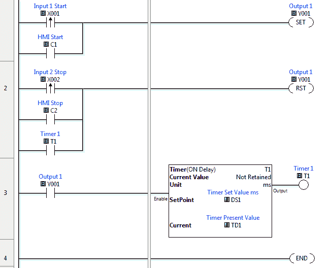
Here is our ladder logic. The first rung will use the set instruction to turn on Output 1 when the physical input X1 transitions from off to on or C1 is turned on.
When you want to control a discrete bit in the programmable controller from the HMI uses an internal contact. In our case, we are using C1.
Note: You can only read the physical IO and not control them from the HMI if the logic in the PLC controls the physical IO.
The second rung will use the reset instruction to turn off Output 1. This will happen on the leading edge of the physical input X2, C2 controlled by the HMI, or the Timer 1 done bit.
The third rung will control the timer. Output 1 will start Timer 1. Timer 1 is an on-delay timer with a SetPoint value (SV) of DS1 and a Current value (PV) of TD1. DS1 and TD1 are registers that can be read or written to by the HMI.
The Click PLC Series can be seen here. This will demonstrate the hardware, communications, and software of this programmable controller line.
Click PLC Export Nickname Tags
We will export the nickname tags in our Click PLC program to a CSV (Comma Separated Value) file. This will allow us to use the tags in our C-More program without typing them in again.
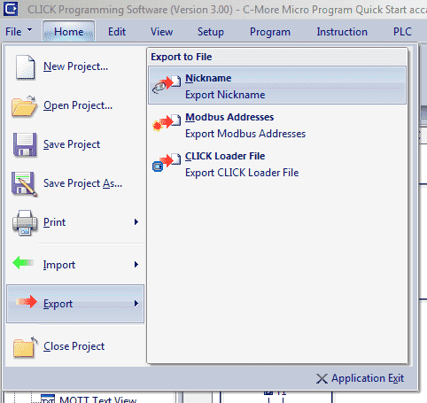
Main menu | File | Export | Nickname
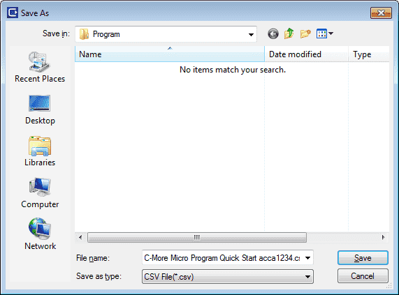
This will call the Save As window. Select the location to save the file and give it a name. Select the Save button to save the tag names.
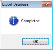
A confirmation will appear indicating that the Export Database operation was completed successfully.
Click Ethernet Port IP
The HMI will be communicating to the Click Ethernet port. It is important that a static IP address is used so that the IP address does not change and disrupt communication.
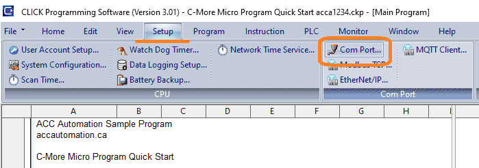
Select main menu | Setup | Com Port…
This will display the COM Port Setup window. You can see that we have several ports to choose from on our Click PLUS controller. Port 1 is our physical Ethernet port. Select the setup button.
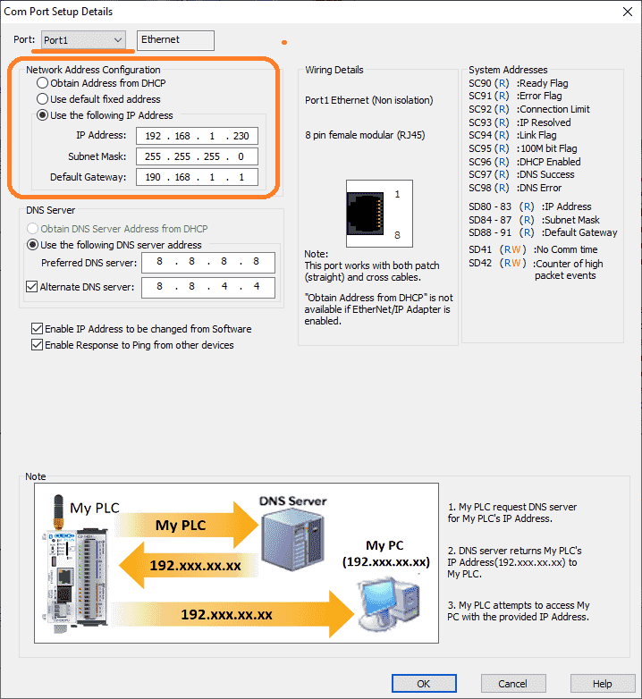
We can now set the IP address we will use with this Ethernet communication port. The subnet mask and default gateway can also be set based on your network configuration.
We now have the PLC program complete with all of the information needed to now develop our C-More Micro HMI program.
C-More Micro Program Setup
The C-More Micro series can be found here. It will review the hardware, communication, and programming software and instructions in detail for this HMI unit. We will assume that the software is installed and we are ready to program.
Double click on the C-more microprogramming software icon on your desktop to start the software.
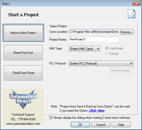
The Start a Project window will now be displayed.
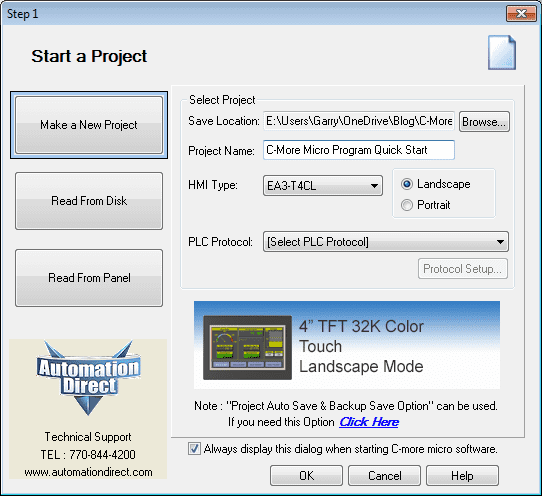
We will name our project C-More Micro Program QuickStart. The HMI type will be EA3-T4CL. You will notice that a picture of the HMI display will be shown to ensure that the correct model has been selected.
Click on the PLC protocol button. The communication protocol is a set of rules that allow two or more devices to transmit information. The devices connected must understand this protocol in order for communication to take place.
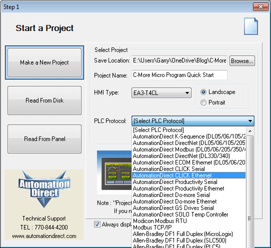
Select the AutomationDirect CLICK Ethernet protocol.
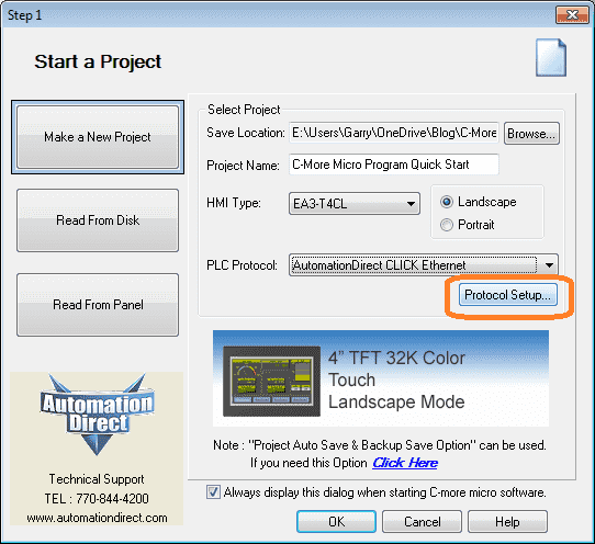
Select the protocol setup button.
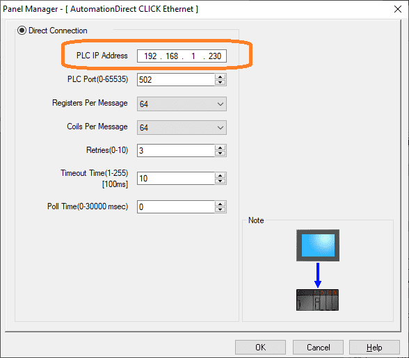
Enter the IP address of the Click PLC Ethernet port that was set up above. Select OK. Select OK again on the start a project window.
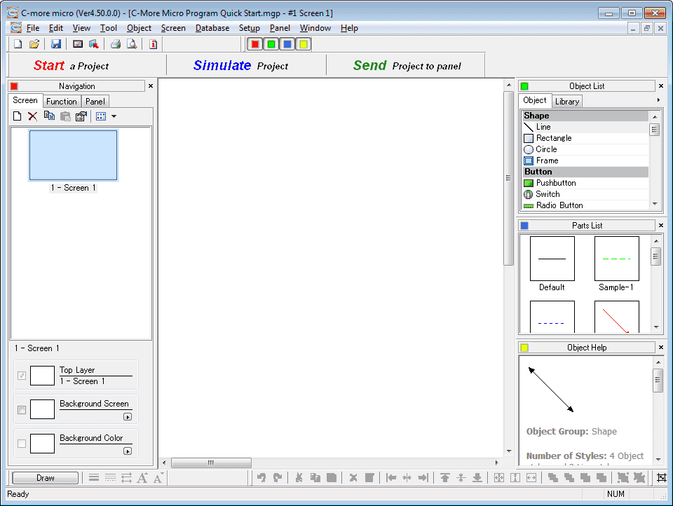
We are now ready to program our HMI.
HMI Development Quick Start
Here are some quick-start development tips to keep in mind for your HMI program:
– Make screens simple to use and follow. The more intuitive the screen is the easier it is for the operator to understand. When things go wrong and the operator is excited, critical information should be readily available and easy to read at a glance.
– Units of measure should be displayed. Make the values displayed obvious to the operator. RPM, Seconds, MPM, or any other unit they may need should be displayed with the values.
– Do not put too much information on one screen. Logically break down and organize the information for the operator. Solicit information from them to include in the organization and control. When operators become part of the solution, they will own it.
– Do not have screens buried too deeply. I like to ensure that information is not buried anymore than three layers (Selections) before the information required is displayed.
– Develop a color code for the screen and keep it consistent. Green is good (go), red is bad (stop). The operator looking at the screen should know instantly information based on color.
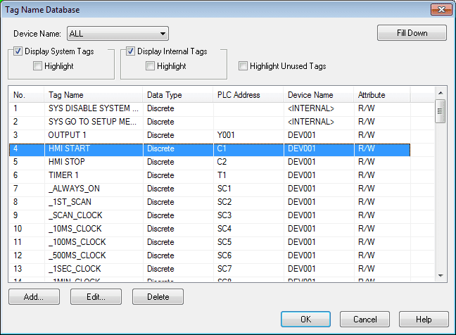
C-More Import Tags
Importing the tags from the PLC program will ensure that we are using the correct address and helps with the documentation of our HMI program.
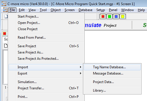
Main menu | File | Import | Tag Name Database…
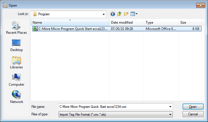
Select the CSV file that we previously saved above and select open.
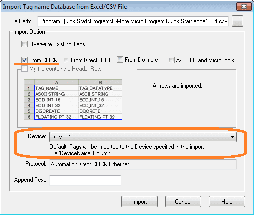
The Import Tag name Database from Excel/CSV File window will be displayed. Import options will default to the selection of ‘From Click’. Select DEV001 for the device. DEV001 is the default device for the protocol selected in the project.
Select the import button.
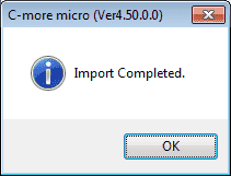
The import complete window will be displayed. Select OK.
C-More Micro Programming Setup
The C-more micro programming software can be set up so it is easier to view display and view the information as you program.
The default zoom on the display is 200%. This will only show a portion of the screen at a time. I prefer to see the entire screen at once. Main menu | View | Zoom…
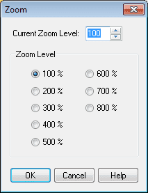
I like to set this as 100% for my screen size. Yours may be different.
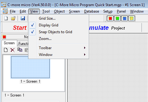
Under the View menu, select the display grid and snap objects to the grid. This will help to align objects on the work area of the HMI software.
We are now ready to program our HMI.
C-More Micro Program
Our C-More Micro program will have only one screen. A start and stop pushbutton will control the Output 1 indication light. Timer 1 set value and present value will be displayed on the screen. The set value will have the ability to change via the HMI screen.
Pushbuttons
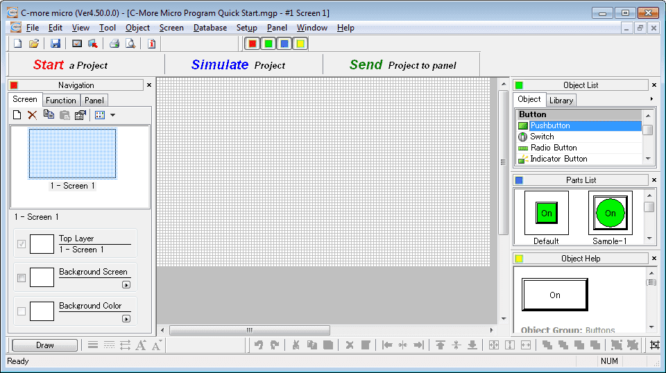
Select pushbutton under the button on the object list. Click and hold the default under the parts list and drag this to the work area.
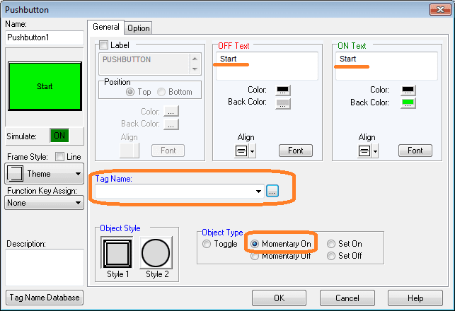
The pushbutton window will now be displayed. Name the OFF Text and ON Text ‘Start’. The object type will be momentary. This means that the contact will only be on for as long as the button is held. Select the tag name.
The tag name database will now be displayed. This is the list of tag names that we have imported above. Select the HMI to start the C1 tag and select OK.
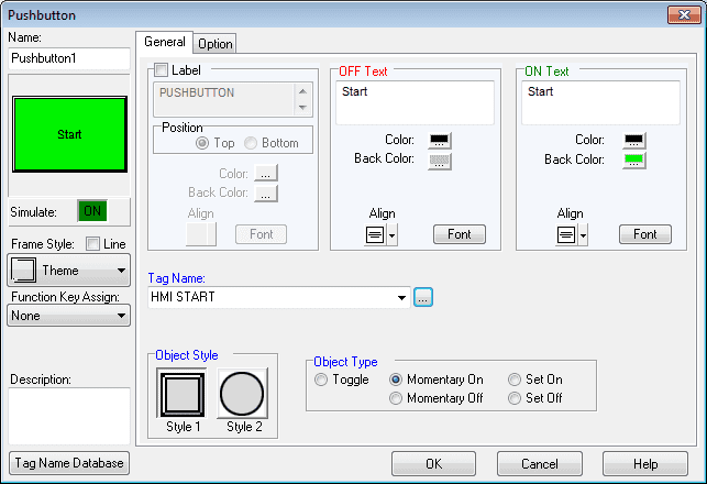
Select OK.
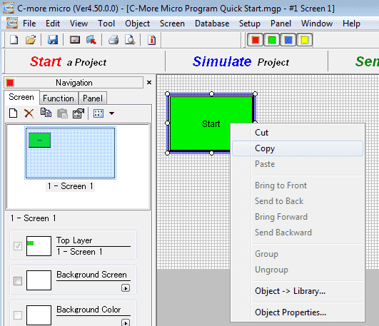
We can now position and size the pushbutton on the screen. Right-click on the push button and select copy. Then right-click on the work area and select paste. This will make a duplicate of the pushbutton. Double-clicking on this pushbutton will bring up its properties.
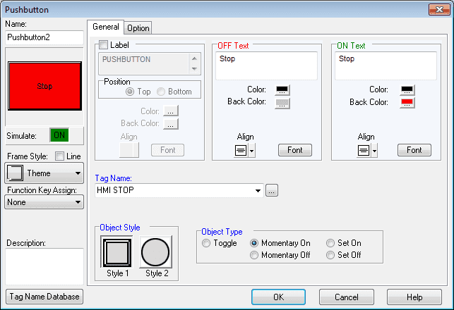
Change the OFF Text and ON Text to Stop. The back color will also be set to red. HMI stop tag (C2) will be used as a momentary-on. Select OK. We can now position our stop pushbutton under the start pushbutton. This is where the snap to grid option comes in handy on the screen.
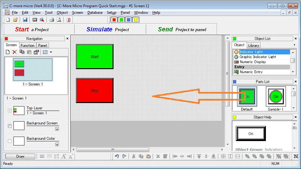
Select Indicator light in the object list. Click and hold the default in the parts list and drag to the work area of the HMI program.
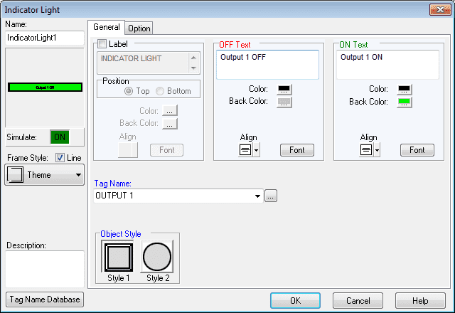
Change the OFF Text and ON Text accordingly and select the OUTPUT 1 tag (Y1) as the Tag Name. Select OK. Size and position the indicator light on the screen.
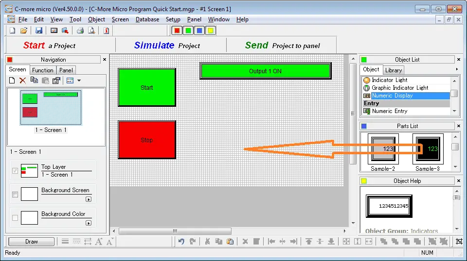
Select numeric display under the object list. Click and drag sample 3 to the work area.
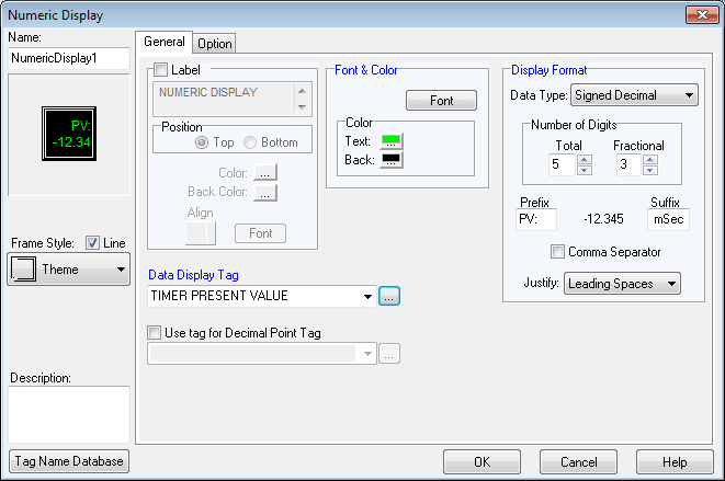
Our timer is in milliseconds so the number of digits will be 5 with 3 fractional (decimal points). The prefix will be PV: meaning present value. The suffix will be ‘mSec’ for the unit of measure. Use font size 16 x 32 so it will be large enough to be seen on the screen. The data display tag will be the timer present value (TD1). Select OK. Size and position the display on the screen.
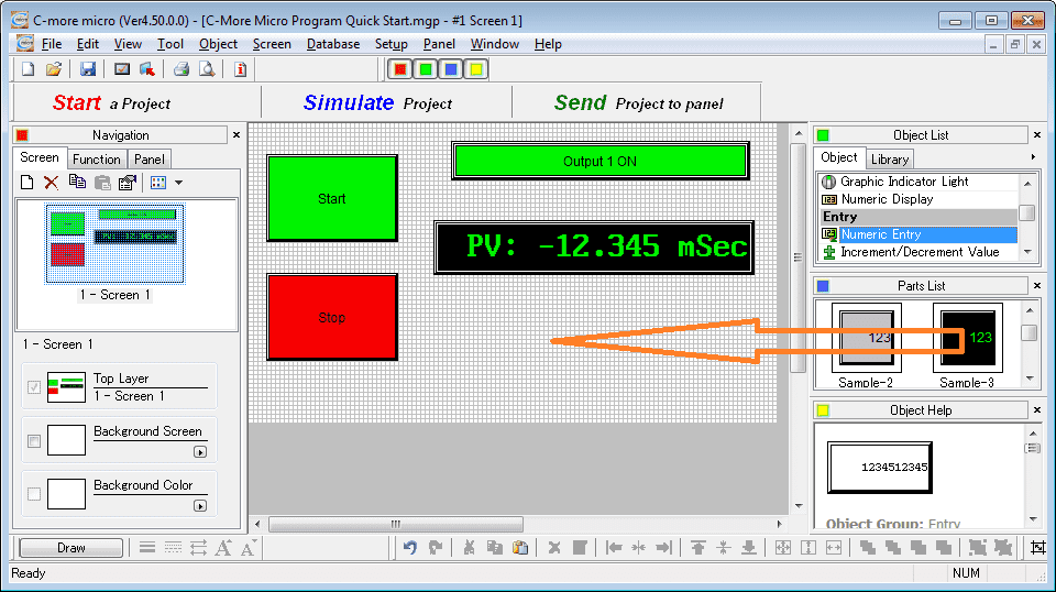
Select numeric entry from the object list. Click and drag sample 3 to the work area.
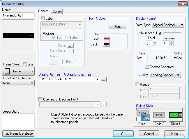
The display format will be the same as the present value. The font size will also be the same but red instead of green. The data entry tag and data display tag will be the timer set value (DS1). Select OK.
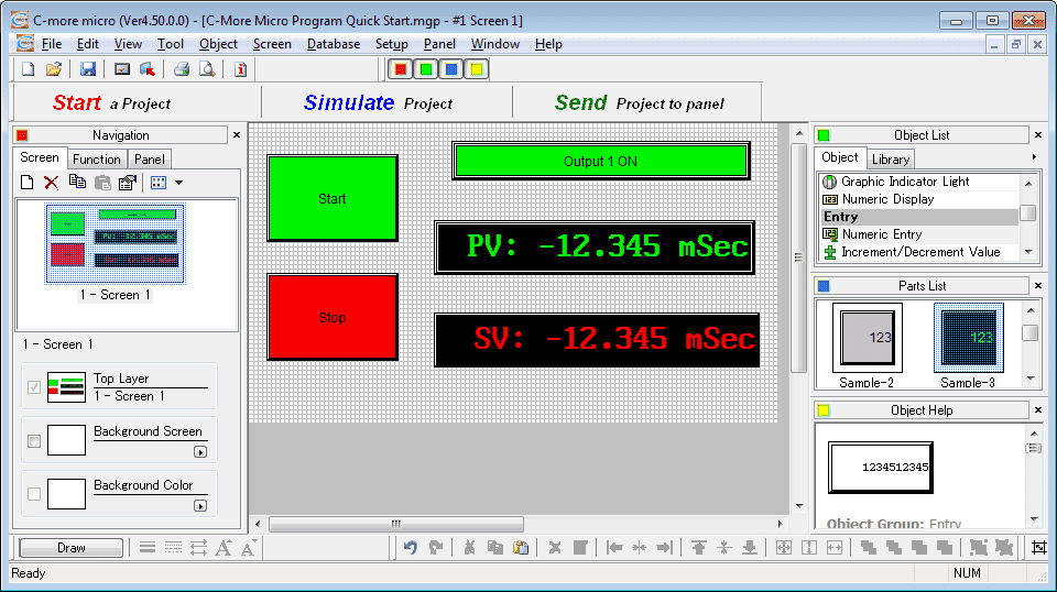
Size and position the numeric entry on the screen. We have now completed the C-More Micro HMI programming.
C-More Micro Simulator
The simulator is used to closely display what your screen will look like. Functions of the screen can be manually done to simulate the PLC logic. There is no communication to automatically update the information.
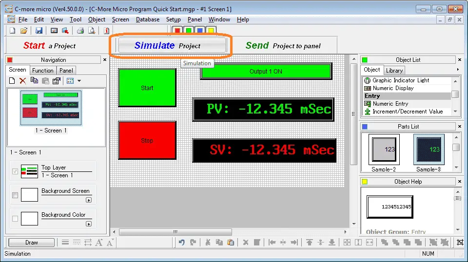
Select the simulate project button on the main menu.
The simulator will display on two separate windows. One will be a representation of the actual screen.
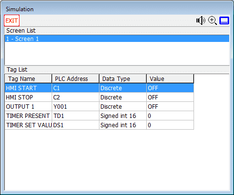
The second window will allow you to view/change the data.

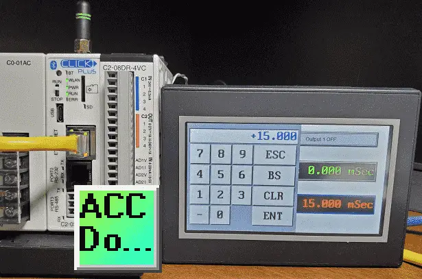
Clicking on the set value of the timer will allow you to enter a value.
C-More Micro Program Transfer
Once you are happy with the basic functionality and look of the screens, we can then transfer the program to the c-more micro-unit.
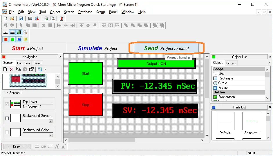
Select the send project to the panel icon on the main screen of the programming software.
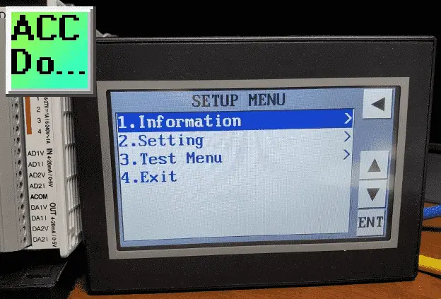
Ensure that the C-More Micro EA3-T4CL is powered and the communication cable (Ethernet) is attached. Since no information is currently in the HMI it will display the setup menu.
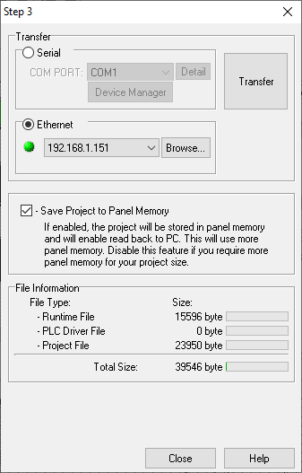
The transfer screen window in the programming software will now be displayed. Select Ethernet as the transfer method. The green dot to the left of the IP address indicates that we have a connection to the HMI. If the dot is red then click the browse button. This will then scan the network and see if a controller exists.
Select the Transfer button on the right-hand side to start the transfer.
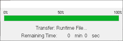
The program will now be sent to the c-more micro HMI,
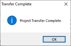
When the program transfer is complete a message will be displayed. Select OK.
C-More Micro Testing
We can now test the physical hardware. In the Click programming software, we can call up the Data View.
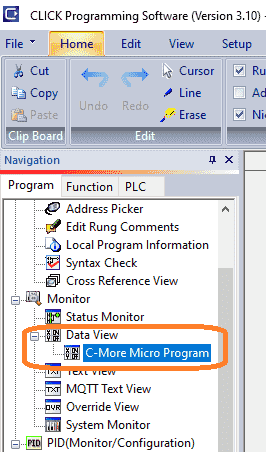
This will allow us to monitor the inputs, outputs, and registers in the PLC.
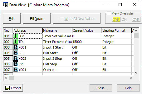
As we operate the HMI the corresponding information in the Data View will be displayed.
Ensure you try all of the functions of the program to ensure correct operation.
Download the PLC and C-More Micro programs here.
Watch the video below to see the C-More Micro Program QuickStart in action with our Click PLC program.
C-More Micro Panels from Automation Direct
https://www.automationdirect.com/adc/Shopping/Catalog/HMI_(Human_Machine_Interface)/C-more_Micro_Panels
C-More Micro – Graphic Panel (EA3 Series) User Manual and Quick Start Guides
https://cdn.automationdirect.com/static/manuals/ea3mguserm/ea3mguserm.html
EA3-T4CL C-More Micro Specifications
https://cdn.automationdirect.com/static/specs/ea3t4cl.pdf
C-More Micro Programming Software V4.35
http://support.automationdirect.com/products/cmoremicro.html
This free software will enable you to program all of the C-More Micro HMI units. It includes a simulator for your application.
Watch on YouTube: C-More Micro Program Quick Start
If you have any questions or need further information please contact me.
Thank you,
Garry
If you’re like most of my readers, you’re committed to learning about technology. Numbering systems used in PLCs are not difficult to learn and understand. We will walk through the numbering systems used in PLCs. This includes Bits, Decimal, Hexadecimal, ASCII, and Floating Point.
To get this free article, subscribe to my free email newsletter.
Use the information to inform other people how numbering systems work. Sign up now.

The ‘Robust Data Logging for Free’ eBook is also available as a free download. The link is included when you subscribe to ACC Automation.