In this tutorial, I am going to walk you through the Conveyor Scene in the ACC PLC Simulator. This is a single-axis belt conveyor with proximity sensors at each end and a box that travels back and forth along the belt. You will write a ladder logic program that starts the conveyor, detects the box at each end using the proximity sensors, reverses direction, and stops the system on command.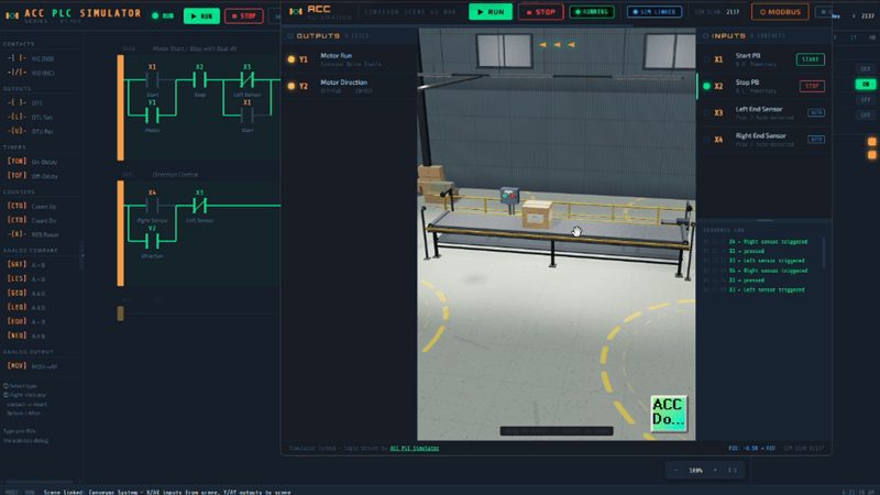
This is the second scene tutorial in the series. If you have not used the simulator before, start with the Control Panel Scene Tutorial to learn the basics of the interface.
Try it now: accautomation.ca/simulator/
What You Will Learn (Conveyor System Tutorial)
This tutorial introduces concepts you will use on every conveyor system in industrial automation.
- Motor starts and stops with a seal-in latch
- Direction control using a separate output bit
- Proximity sensor detection and how sensors trigger logic changes
- Automatic reversing based on sensor position
- The Five-Step PLC Program Development Framework applied to a real machine
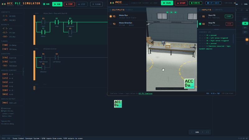
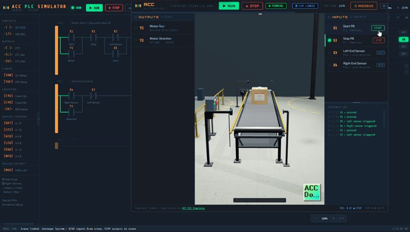
The Conveyor Scene
The Conveyor Scene is a belt conveyor modeled in 3D. A box sits on the belt and travels in the direction determined by your PLC logic. Proximity sensors at the left and right ends detect when the box arrives at each end. You can orbit around the scene, zoom in, and watch the belt move and the box travel in real time.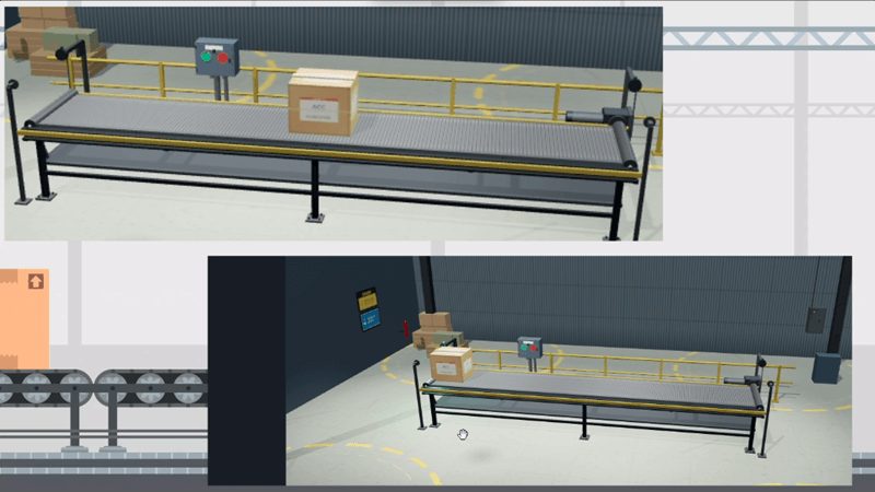
I/O Map
Here is the I/O map for the Conveyor Scene. Six I/O points total — four inputs and two outputs.
| Address | Direction | Description | Notes |
|---|---|---|---|
| X1 | Input | Start pushbutton | Normally Open, momentary |
| X2 | Input | Stop pushbutton | Normally Closed, momentary |
| X3 | Input | Left Sensor | Proximity sensor, left end of belt |
| X4 | Input | Right Sensor | Proximity sensor, right end of belt |
| Y1 | Output | Motor Run | ON = conveyor belt is moving |
| Y2 | Output | Direction | OFF = Forward (left to right), ON = Reverse (right to left) |
X1 and X2 work exactly like the Control Panel Scene. X1 is your Start button and X2 is your Stop button wired Normally Closed. X3 and X4 are the new I/O in this scene. These are proximity sensors that go TRUE when the box arrives at their position and FALSE when the box moves away.
Y1 controls the motor. When Y1 is ON the belt moves. Y2 controls direction. When Y2 is OFF the box moves forward (left to right). When Y2 is ON the box moves in reverse (right to left).
Applying the Five-Step Framework (Conveyor System Tutorial)
I always recommend using the Five-Step Framework when developing a PLC program. It keeps your thinking organized and prevents you from jumping into ladder logic before you understand the problem. Here is how I would apply it to this conveyor.
STEP 1 — Define the Task
Write down in plain English what the system must do.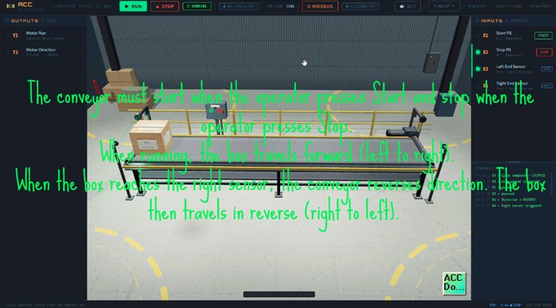
The conveyor must start when the operator presses Start and stop when the operator presses Stop. When running, the box travels forward (left to right). When the box reaches the right sensor, the conveyor reverses direction. The box then travels in reverse (right to left). When the box reaches the left sensor, the conveyor stops automatically. The operator can press Start again to repeat the cycle. The Stop button must stop the conveyor at any time regardless of where the box is.
STEP 2 — Define the I/O
We already have the I/O map from the scene. Four inputs and two outputs. No analog I/O needed for this application. This step is already done.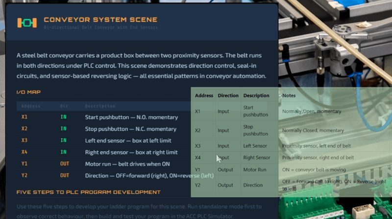
STEP 3 — Develop a Flow Chart
Here is the sequence of operations.
- Operator presses Start (X1)
- Motor starts (Y1 = ON), Direction = Forward (Y2 = OFF)
- Box travels left to right
- Box arrives at right sensor (X4 = TRUE)
- Direction reverses (Y2 = ON)
- Box travels right to left
- Box arrives at left sensor (X3 = TRUE)
- Motor stops (Y1 = OFF)
- System is ready for the next cycle
The Stop button (X2) can interrupt at any point and immediately stop the motor.
STEP 4 — Develop the PLC Program
Now we translate the flow chart into ladder logic. I will break this down rung by rung.
Rung 0 — Motor Start / Stop with Seal-In
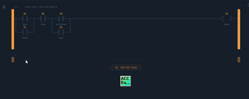
This is the same Start/Stop seal-in pattern from the Control Panel tutorial. X1 (Start) as a normally open contact in parallel with Y1 (seal-in), followed by X2 (Stop) as a normally open contact in series reading the N.C. bit. Add X3 (Left Sensor) as a normally closed contact in series. Then add X1 (Start) in parallel with the XIO X3 contact. The output is Y1 (Motor Run).
The X3 normally closed contact is the automatic stop. When the box arrives at the left sensor, X3 goes TRUE. Since we are using a normally closed contact (XIO), this will open and break the power flow to Y1. The motor stops and the seal-in breaks. The X1 contact in parallel with XIO X3 is important. After the first cycle the box is sitting at the left sensor so X3 stays TRUE. Without X1 in parallel the motor would never start again. With X1 in parallel, pressing Start bypasses the left sensor and allows the motor to run. Once the box moves away from the left sensor, X3 goes FALSE, XIO X3 passes power, and the seal-in holds through Y1. This gives us both a manual stop (X2) and an automatic stop (X3 at the left end) while still allowing a restart.
Rung 1 — Direction Control
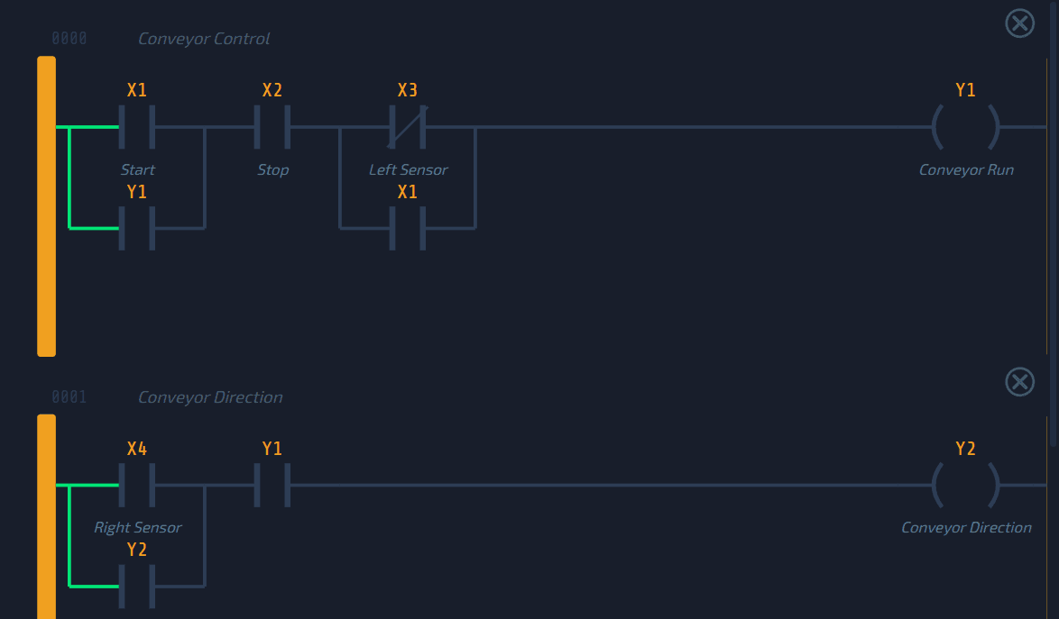
When the box reaches the right sensor (X4), we need to reverse direction. Use X4 (Right Sensor) as a normally open contact. Add Y2 (Direction) in parallel as a seal-in so the direction stays reversed after the box moves away from the right sensor. The output is Y2 (Direction).
We also need to reset the direction when the motor stops. Add Y1 (Motor Run) as a normally closed contact in series with the seal-in branch. This way, when the motor stops, Y2 resets to OFF (forward) for the next cycle. Alternatively, you could add X3 (Left Sensor) as a normally closed contact to reset direction when the box reaches the left end.
STEP 5 — Test the Program
Connect the Conveyor Scene and test the full sequence.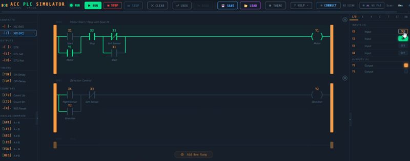
- Press Start — the belt starts moving forward
- Watch the box travel to the right
- The box hits the right sensor (X4) — direction reverses automatically
- The box travels back to the left
- The box hits the left sensor (X3) — the motor stops automatically
- Press Start again — the cycle repeats
- Press Stop during travel — the motor stops immediately
If any step does not work, use Step mode in the simulator. Toggle the inputs manually and press Step to see exactly which contacts are passing power and which are not.
Connecting the Scene (Conveyor System Tutorial)
To connect the Conveyor Scene to the simulator:
- Open the simulator at accautomation.ca/simulator/
- Click CONNECT in the toolbar
- Find the Conveyor System card in the scene list
- Click LAUNCH
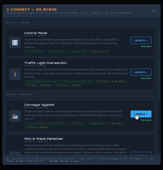
The scene opens in a new window and connects automatically. You will see SIM LINKED in both the simulator and the scene. Now build your ladder logic, put the simulator in Run mode, and press the Start button.
Tips (Conveyor System Tutorial)
Here are some things I have learned working with conveyor programs.
Use the proximity sensors as both inputs to your logic and as automatic stop conditions. In this program X3 serves double duty — it is both the left sensor input and the automatic stop. This is a common pattern in real conveyor systems.
Test the Stop button at every stage of the cycle. Press Stop when the box is traveling forward. Press Stop when the box is traveling in reverse. Press Stop when the box is at a sensor. Make sure the motor stops cleanly in every case.
Pay attention to the direction reset. If you do not reset Y2 when the motor stops, the next cycle will start in reverse. The normally closed Y1 contact in the direction seal-in handles this automatically.
Think about what happens after a completed cycle. The box is sitting at the left sensor so X3 is TRUE. The XIO X3 contact in the motor rung is open. But because we added X1 in parallel with XIO X3, pressing Start bypasses the sensor and the motor starts. As soon as the box moves away from the left sensor, X3 goes FALSE and the seal-in takes over. This is a common pattern in conveyor programs — use the Start button to override a sensor interlock during the initial startup.
What You Learned
In this tutorial you built a conveyor control program using the Five-Step Framework. You used proximity sensors as inputs to trigger automatic direction changes and automatic stops. You applied the seal-in latch pattern to both the motor control and the direction control. And you learned how to use a normally closed sensor contact as an automatic stop condition.
The Conveyor Scene introduces I/O patterns that you will see in every material handling system — motors, sensors, direction control, and automatic sequencing. These are fundamental building blocks for more complex machines like the Pick and Place Palletizer and the Bottle Sort Line.
Watch on YouTube: PLC Programming Tutorial: Build a Conveyor System (ACC Simulator)!
What is Next
Try modifying the program…
– Add a counter to track how many complete cycles the box has made.
– Add a timer to pause for 2 seconds at each end before reversing.
The simulator supports all of these and more.
Head over to accautomation.ca/simulator/ and try it yourself. If you found this helpful, subscribe to ACC Automation on YouTube for more PLC tutorials. And leave a comment telling me what program you would like to build next.
If you have any questions or need further information, please contact me.
Thank you,
Garry