This EMR Applications article was written by Chris Urban, an automation educator and PLC trainer with over 40 years of hands-on experience. Find Chris on YouTube and LinkedIn. — CU
In the complex world of automation, reliability often boils down to a single, fundamental component: the electromechanical relay (EMR) contact. Whether you are troubleshooting a legacy system or designing the next generation of control panels, understanding how these contacts actually function under load is non-negotiable.
While modern drives and PLCs dominate our control strategies, the humble EMR remains the essential “muscle” that physically closes the loop between low-voltage signals and high-power applications. In this article, Chris peels back the technical layers of EMR contacts, moving beyond simple theory to provide the practical knowledge you need to specify, wire, and maintain reliable systems that won’t fail when it matters most. – Garry
This is the fifth article in the relay series. If you are new to relay symbols and abbreviations, start with the relay glossary before reading this one — the terminology used throughout this article is defined there.
Now that you can recognize all the relay symbols from the glossary, let’s start with the simplest ones.
SPST — The Backbone of PLC Output Modules
The SPST relay is found inside virtually every PLC relay output module ever made. It is the simplest possible contact arrangement — one Common, one NO contact, nothing else.
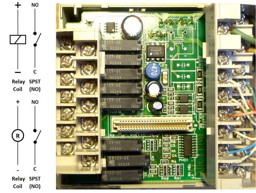
Omron CPM1A relay board – top view
Notice that the relay coil symbol appears in two distinctive ways. The symbol in the top-left corner is used in electronic schematics. The symbol in the bottom left appears in relay and ladder logic diagrams. Both represent the same physical coil — the context determines which style is used.
On one external relay board, an Omron module carries a full array of 16 SPST relays:
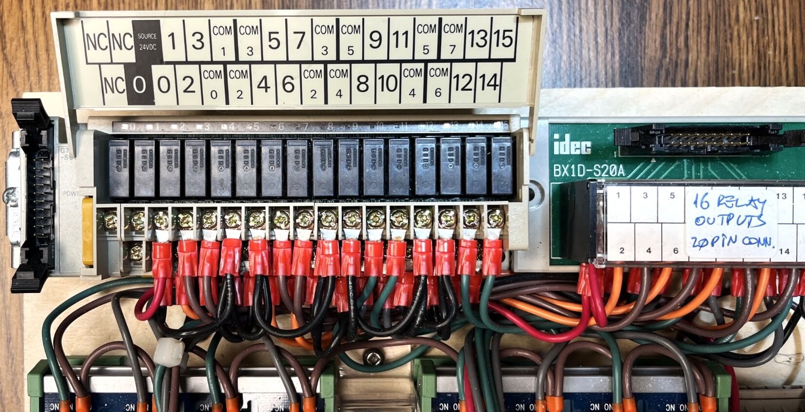
16 SPST relays on Omron external relay board
The same NO output contacts are visible on a Crouzet PLC trainer board:
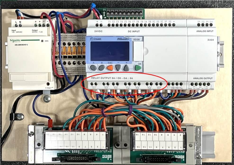
Crouzet PLC NO output contacts
SPDT — One of the Most Common PLC Relay Configurations
The SPDT makes a full group of three contacts — Common, NC, and NO. It is found everywhere in PLC applications and gives you considerably more flexibility than the SPST alone.
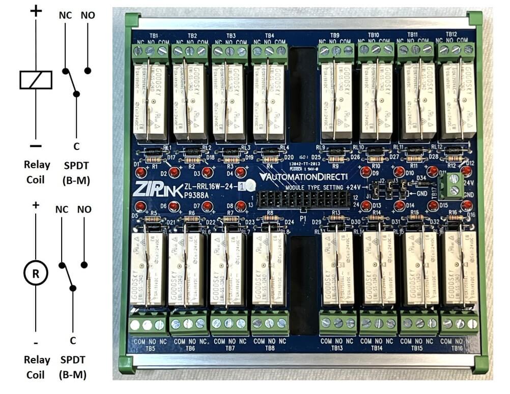
AutomationDirect 16-relay SPDT block
You can connect the transistor PLC outputs directly to an AutomationDirect 16-relay block using the appropriate cable. Here is the same connection of the same block to a Modicon PLC.
Modicon PLC connected to the AutomationDirect relay block
Two Groups of Contacts
When your application requires two groups of contacts, you will encounter three very common relay housings:
- Option 1 — Two groups of contacts on a sealed 8-pin PCB type relay
- Option 2 — Two groups of contacts on an 8-pin relay, pins on two rows
- Option 3 — Two groups of contacts on an 8-pin relay, round socket
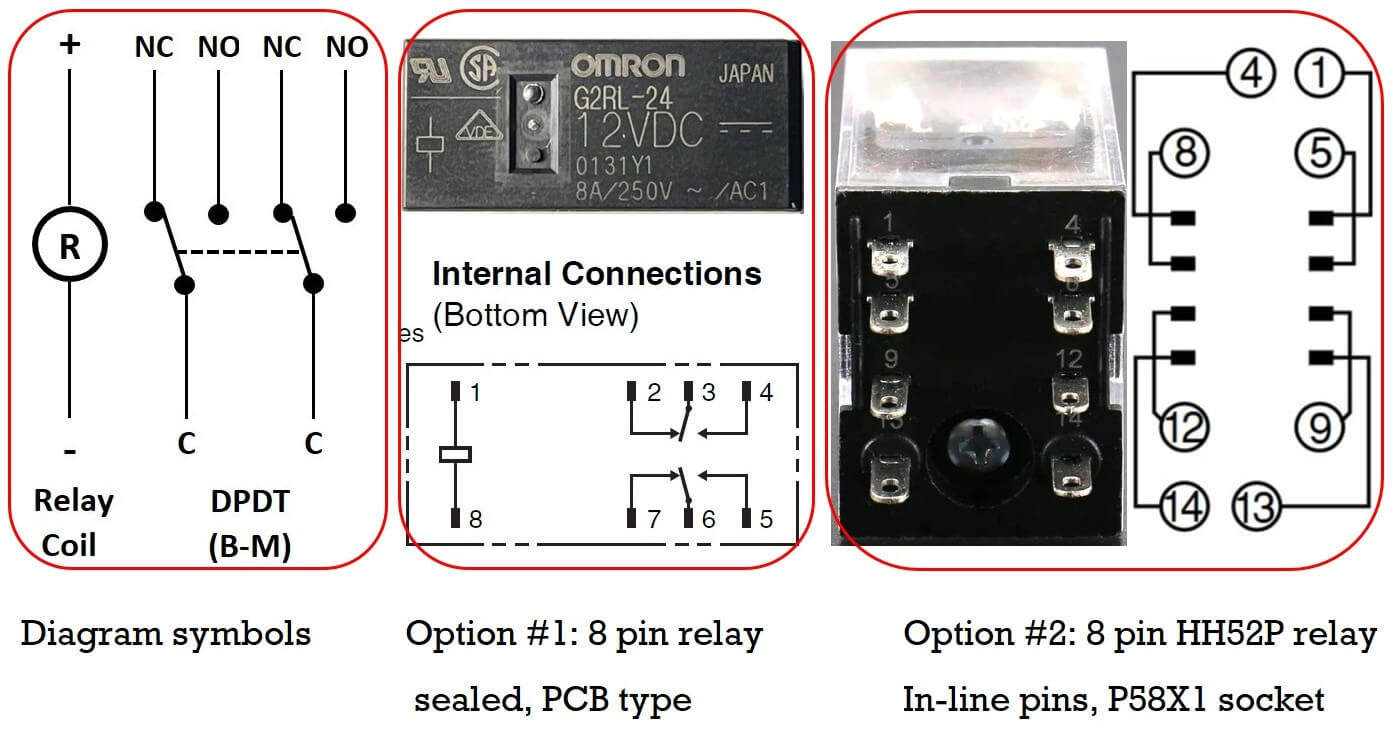
Three relay housing options side by side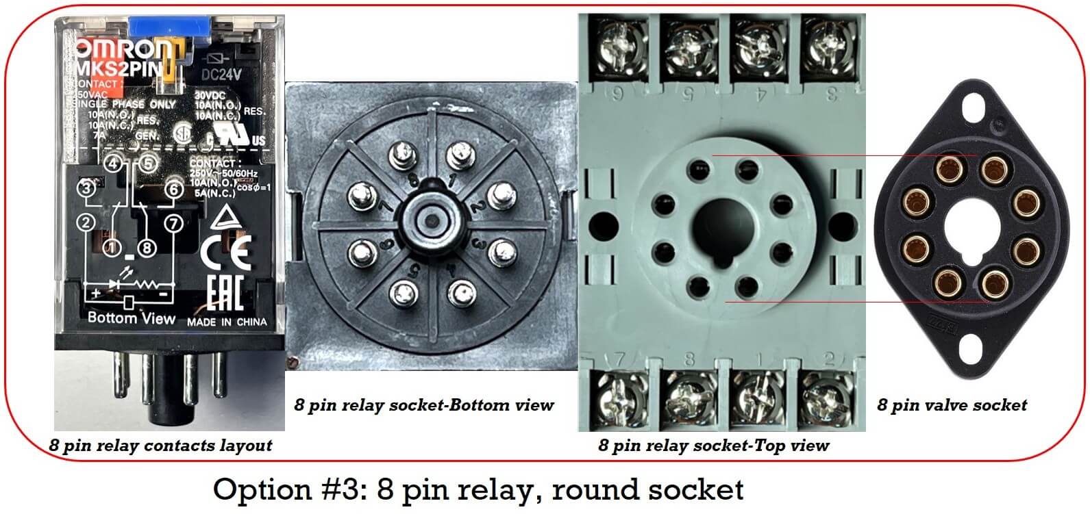
Round socket relay next to vacuum tube socket
A Little Piece of History
The round relay pins and sockets — both 8-pin and 11-pin — are a direct inheritance from the vacuum tube era. Pick up an 8-pin relay, and it will fit perfectly in a valve socket. The valves themselves are still in use in 2026, mostly in high-end audio and guitar amplifiers. Not out of nostalgia, but because of a genuine passion for sound quality. Go into a showroom and listen to one — you will understand.
Valve and gold-plated sockets are widely available online. Despite the excellent quality of some valve sockets, dedicated relay sockets are still recommended because they are almost all DIN-rail ready.
Option 3 EMR Applications — The Crossover Switch for Motor Direction Control
Here is the basic connection diagram from a Siemens PLC trainer manual:
Getting Started — Beginners Training Documents, 07/2007, A5E01031470B, page 10/49
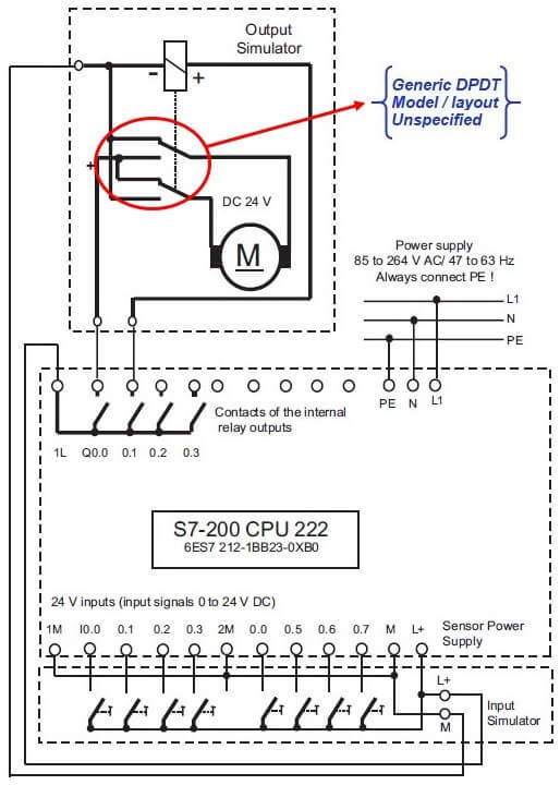
Siemens PLC trainer motor direction control schematic
Depending on motor size and power consumption, inserting a power relay between the PLC outputs and the motor makes sense. It also protects the PLC outputs if the motor stalls or becomes overloaded. Notice that the relay and DC motor are drawn inside a dotted frame — they form a detachable assembly, which is a smart design choice. The relay is mandatory if you want to use that assembly with a PLC wearing transistor outputs.
The two PLC outputs involved are Q0.0 and Q0.1, both relay type. Q0.0 controls forward, Q0.1 controls reverse.
When Q0.0 is actuated, the NO contact closes, connecting the motor’s left side to the positive supply.
The right side of the motor connects to the negative supply via the relay’s NC contact, and the motor starts turning forward.
When Q0.1 is actuated, it energizes the relay coil.
The relay now works as a crossover switch.
The left side of the motor connects to the negative supply, and the right to the positive.
Polarity across the motor brushes is reversed — and the motor reverses.
What Happens If Both Outputs Activate at the Same Time?
This is a classic beginner mistake — and it deserves a proper explanation.
A motor revolves because of the interaction between two magnetic fields: the stator and the rotor. When the motor starts from rest, the only opposition to current flow is the coil’s ohmic resistance. As the motor accelerates, it develops inductance. Combined with the resistance, the overall opposition increases until the motor reaches rated speed — at which point a balance is established.
Now imagine switching direction rapidly — ten times per second — while the motor is energized. The inductance has no time to develop. The only opposition remaining is the copper resistance of the rotor coil, which is very low. Any voltage divided by a very low resistance produces a very high current, which means very high dissipating power — and very high heat.
The rotor is designed to turn with minimum friction, which normally keeps it cool. But if it starts to heat up, that heat has very little path out. The bearings provide almost no thermal contact with the housing, and the shaft fan cannot compensate. A stalling motor under power will eventually fail.
There is good news in this particular circuit design: if both Q0.0 and Q0.1 activate simultaneously, the motor simply continues in reverse rather than stalling. The crossover switch geometry provides that natural protection.
For any physical PLC trainer you build, applying the same electric arrangement will keep your motor safe. And in your PLC program, always include an interlock sequence preventing the FWD and REV commands from reaching the outputs simultaneously. For industrial three-phase AC motor control, these interlocks are mandatory.
Here is a sketch adapting the crossover switch to any PLC model. The output numbers are left blank — fill them in according to your specific PLC:
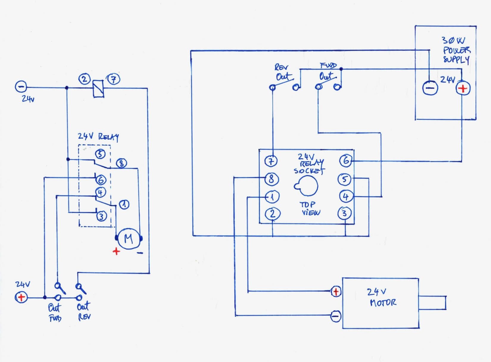
Crossover switch sketch for any PLC
The output trainer shown here works with any PLC. Watch the two videos below to see it in action:
Note A: A full series of these videos is available on Chris’s YouTube channel in two playlists:
DIY Low Power PLC Trainer and Your Time to Shine.
Note B: The two contacts on the top right of the sketch belong to two additional slim relays.
If your PLC has relay outputs, the slim relays act as simple buffers. If your PLC has transistor outputs, the slim relays convert those transistor outputs into relay outputs capable of driving the motor.
Note C: Always include an interlock sequence in your program to prevent FWD and REV commands from reaching the PLC outputs simultaneously. For three-phase AC motor control, this is a requirement, not an option.
Option 2 EMR Applications — LED Signal Tower with AC Drive Fault Monitoring
Only the Red and Green LEDs from the tower are needed here — the amber is not required, and the buzzer was left disconnected because the sound was too annoying.
The Emerson SK AC drive has a signal called Inhibit. When the drive is running normally, Inhibit is OFF. When anything goes wrong, Inhibit goes ON. A DPDT relay monitors this signal.
As long as there is no warning, the Green light stays ON. When the Inhibit signal appears, the relay coil energizes — Red goes ON and Green goes OFF. Simple and effective.
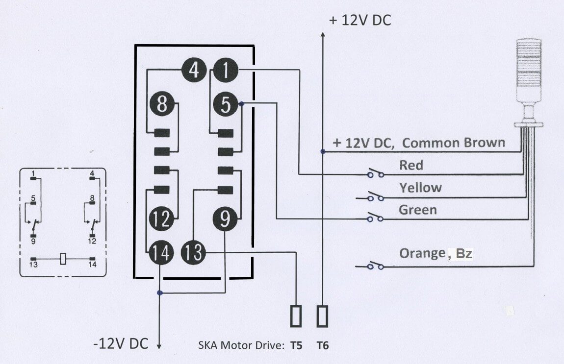
Emerson drive Inhibit monitoring circuit diagram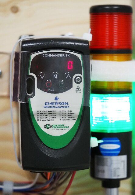
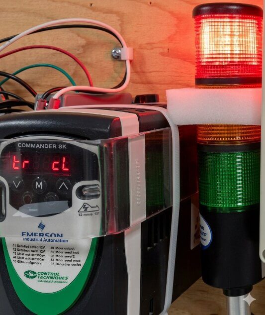
Red/Green signal tower / Emerson SK drive Inhibit in action
Option 1 EMR Applications — The 5 Second Rule Digital Helper
PCB type relays are among the most common components in low-power electronics. Here is an unusual project using DPDT contacts:
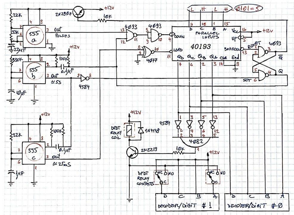
Electronic diagram — The 5 Second Rule Digital Helper
Watch the full project on Chris’s YouTube channel: The 5 Second Rule Digital Helper
Three Groups of Contacts — Switching Between Contactor and VFD
TPDT relay symbol
A three-phase motor can be driven either by a contactor block or by a Variable Frequency Drive. The simplest way to switch between the two is a relay with three groups of contacts — shown in the red dotted frame below.
The relay coil is controlled by one PLC output. By default, as long as variable speed is not needed, the VFD remains idle, and the motor is controlled through the NC contacts.
When the PLC output energizes the relay, the motor switches to VFD control through the NO contacts. The presence of the relay requires no change to the rest of the program.
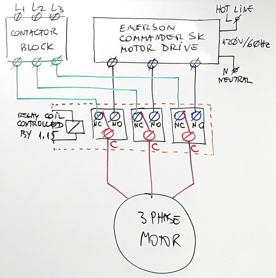
TPDT relay switching between the contactor and VFD
One Last Example — QPDT Used as TPDT
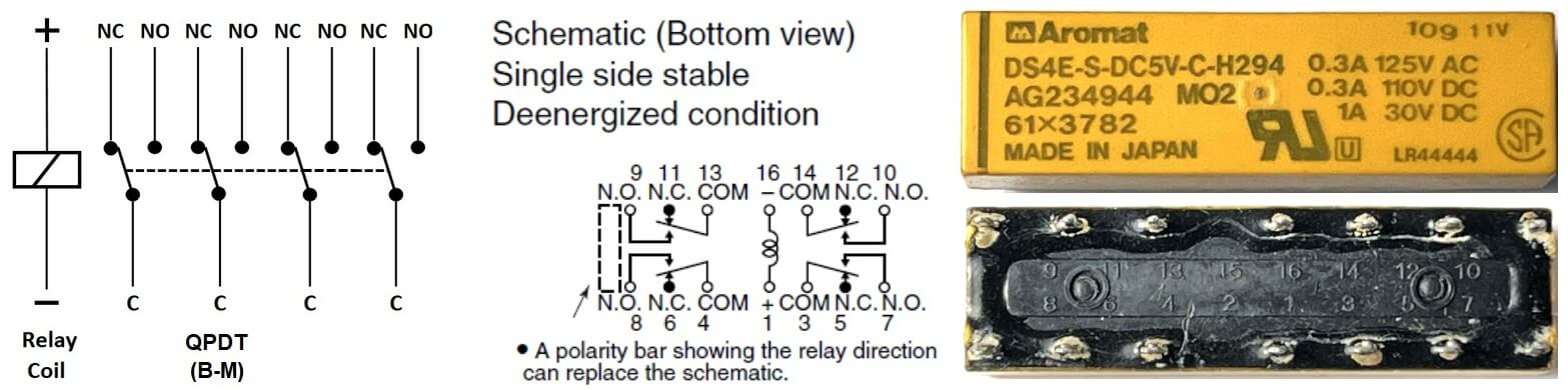
QPDT relay symbol
This relay was not in the glossary, but follows the same pattern — a Quad Pole Double Throw.
In this application, it is used as a TPDT, with one group of contacts left unused. A sealed PCB TPDT relay was simply not available, so a QPDT was used instead.
The application: sharing a non-wireless printer between two computers without swapping cables — just flip a toggle switch. Three USB printer cables are all that is needed.
Additional PCB relay resources from Chris’s channel:
- Connect SAFELY Your Breadboard Project to AC Loads
- Two-way AC Load Connection Diagrams — Version 1 and Version 2
- PCB Relays Intro — With Practical Demos
- Test Your PCB Relays — Awesome Little Project
This article is part of Chris Urban’s relay series on ACC Automation. Read the full series:
The Relay Obituary? Not So Fast!
· Relay Symbols and Abbreviations Glossary
· EMR Contacts in Applications
Want to practice relay output logic in ladder logic? Try the free ACC PLC Simulator — runs in your browser, no install required.
About the author: Chris Urban is an automation educator and PLC trainer with over 40 years of hands-on experience. Find him on YouTube and LinkedIn. — CU