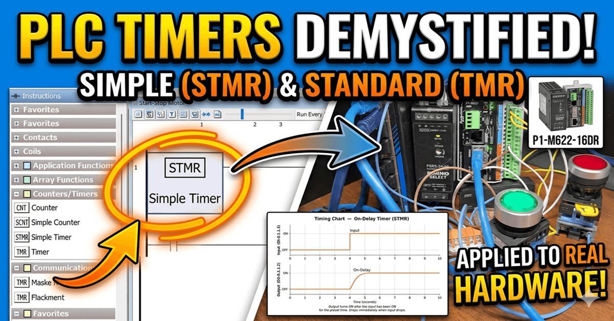
Almost every PLC program includes a timer instruction. The Productivity Mini PLC P1-M622-16DR (P1 Mini) offers several timer instructions. (P1 Timer) We discussed the Timed Coil (TMC) and Flasher Coil (FLS) in our last post as part of our discussion of contacts and coils. In this session, we will review the instructions for the Simple Timer (STMR) and Timer (TMR) in the Productivity Suite software.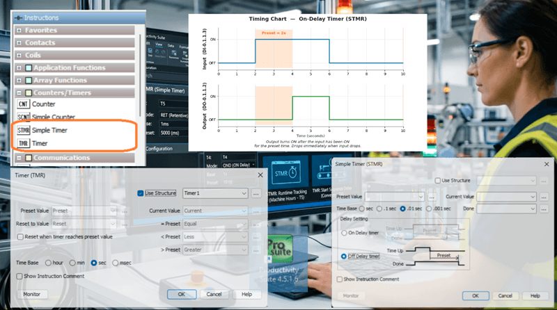
We will build on our start-stop motor circuit from earlier in this series and demonstrate practical timer examples that you can use in real programs.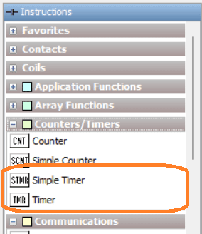
Let’s get started.
Previously in this Productivity Mini PLC P1-M622-16DR series, we have discussed:
P1-M622-16DR Mini PLC System Hardware – Video
Installing the Software – Video
Establishing Communication – Video
First Program – Video
Monitoring and Testing the Program – Video
Wiring and Testing – Video
Online Editing and Fail-Safe Wiring – Video
Using the Productivity Suite Simulator – Video
Numbering Systems and Tag Database – Video
Contact and Coil Instructions – Video
Timing Diagrams – Productivity Timer
Timers are used in most PLC programs. Before writing a single rung of timer logic, it is important to understand the timing chart — also called a timing diagram. A timing chart is a visual representation of how inputs and outputs relate to each other over time. It shows you exactly when an output should turn on and off relative to its input, which determines which type of timer you need.
We have covered timing charts in detail in the following post: https://accautomation.ca/the-secret-of-using-timers/
Understanding the timing chart first will save you a great deal of troubleshooting time later. Always sketch your timing chart before building your rungs.
Simple Timer (STMR) – On Delay Timer – P1 Timer
The Simple Timer (STMR) is the most straightforward timer in the Productivity Suite. It is found in the Timer/Counter category of the Instructions list. The STMR has two operating modes: On-Delay and Off-Delay.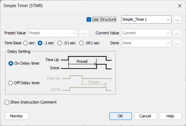
On Delay — The output turns ON after the input has been ON continuously for the preset time. If the input turns OFF before the timer expires, the current value resets to zero, and the timer restarts when the input turns ON again.
Setting up the Simple Timer using the Structure: P1 Timer
When you add an STMR to your ladder, you will be prompted to enter the addresses individually or use the Structure option. Select Use Structure. Give it a name — for this example, we will use Simple_Timer1. Using the structure automatically creates the following tags:
- Simple_Timer1.Preset – 32-bit integer. The time value the timer counts to.
- Simple_Timer1.Current – 32-bit integer. The current accumulated time value.
- Simple_Timer1.Done – Boolean. Turns ON when Current reaches Preset.
Under the tag definitions, set the Preset value to memory-retentive so it survives a power cycle, and enter an initial value of 100. The STMR time base is 100 milliseconds (0.1 seconds) per count, so 100 counts equals 10.0 seconds.
Time Base: 1 count = 0.1 seconds (100ms) 100 x 0.1 = 10.0 seconds
Practical example with the start-stop circuit:
Now add the STMR instruction to a new rung below your start-stop motor circuit with DI-0.1.1.3 (a switch input) as the rung condition. Add a rung below the STMR instruction. Place a NO contact using Simple_Timer1.Done as the tag, and wire it to an Out coil on DO-0.1.1.2 (a second relay output — an indicator light, for example). 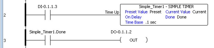
Note: Before testing our circuit, call up the tag database. We can turn on the forceable bits for the inputs and outputs. This will allow us to test all of our inputs and outputs on the CPU unit.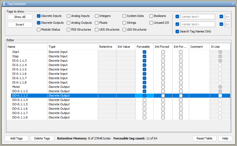
Highlight the two new rungs and right-click. Select the monitor in data view. In the Monitor in Data View window, select Create New Tab. Select OK. We can now monitor our new rungs.
When DI-0.1.1.3 is turned ON, the timer begins counting. After 10 seconds, the Done bit energizes, and DO-0.1.1.2 turns ON. If DI-0.1.1.3 turns OFF before the 10 seconds expire, the current value resets to zero. The output remains OFF.
This is a classic On Delay application — used whenever you want a delayed start: a conveyor that begins moving 10 seconds after a start signal, a warning horn that sounds after a door has been open for a set time, or a motor that needs a warm-up delay before a downstream process begins.
Watch the video below to see this in operation.
Simple Timer (STMR) – Off Delay Timer – P1 Timer
The Off Delay timer keeps the output ON for the preset time after the input turns OFF. The output is ON while the input is ON, and remains ON for the preset duration after the input drops.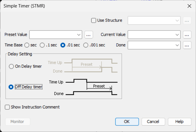
Setting up the Off Delay:
Add a second STMR instruction. Select Use Structure and name it Simple_Timer2. This creates the same three tags:
- Simple_Timer2.Preset – 32-bit integer
- Simple_Timer2.Current – 32-bit integer
- Simple_Timer2.Done – Boolean
Set the Preset to memory retentive with an initial value of 1000 (10.00 seconds). In the STMR instruction block, change the timer mode from On Delay to Off Delay.
How it works:
When the rung input (DI-0.1.1.4) turns ON, the Simple_Timer2.Done output bit turns ON immediately. When DI-0.1.1.4 turns OFF, the timer begins counting. After 10 seconds, the Done bit turns OFF. The timer’s current value resets and is ready for the next cycle.
Practical example with the start-stop circuit:
Imagine you want the motor to continue running for 10 seconds after the operator presses Stop — a motor run-down delay to allow a conveyor to clear before the motor fully stops. Wire the motor’s running status (DO-0.1.1.1) as the rung condition for the Off Delay STMR. Drive a second coil from the Done bit that keeps a downstream device energized. When the motor stops, the downstream device stays on for the 10-second run-down period.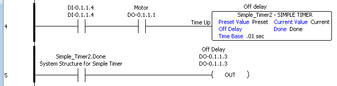
Tip: The On Delay and Off Delay modes of the STMR can each be demonstrated clearly on a timing chart. Draw the input line and the output line before writing your rungs — the relationship between them will tell you exactly which mode you need.
Timer (TMR) – Up/Down Timer with Reset
The Timer (TMR) instruction provides more flexibility than the Simple Timer. It supports independent Up and Down count inputs, a separate Reset input, a selectable time base, and four comparison output bits. This makes it ideal for applications where you need to track elapsed time in multiple directions or trigger outputs at specific time thresholds.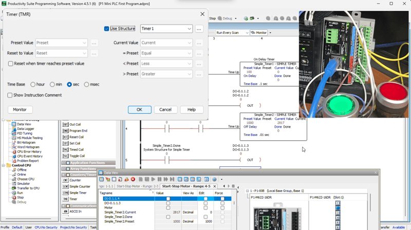
Setting up the TMR using the Structure: P1 Timer
Add a TMR instruction from the Timer/Counter category. Select Use Structure and name it Timer1. Set the Time Base to seconds (sec). This creates the following tags:
- Timer1.Preset – 32-bit integer. The target value for comparison.
- Timer1.Reset – 32-bit integer. The value the current value is set to when reset is triggered.
- Timer1.Current – 32-bit integer. The current accumulated time in the selected time base.
- Timer1.Less – Boolean. ON when Current is less than Preset.
- Timer1.Equal – Boolean. ON when Current equals Preset.
- Timer1.Greater – Boolean. ON when Current is greater than Preset.
Set Preset, Reset, and Current to memory retentive. Set the Preset initial value to 20 (20 seconds).
Time Up input:
Wire DI-0.1.1.5 as the Time Up input. When DI-0.1.1.5 is ON, the timer counts up at the time base rate (1 second per count). The current value increases toward the Preset.
Time Down input:
Wire DI-0.1.1.6 as the Time Down input. When DI-0.1.1.6 is ON, the timer counts down at the time base rate. The current value decreases.
Important: When both Time Up and Time Down inputs are ON simultaneously, the timer does not count in either direction. It holds its current value until one input drops.
Reset input:
Wire DI-0.1.1.7 as the Reset input. When DI-0.1.1.7 is activated, the timer’s current value is set to the Reset value (in our case, 0). This clears the accumulated time and returns the timer to its starting state.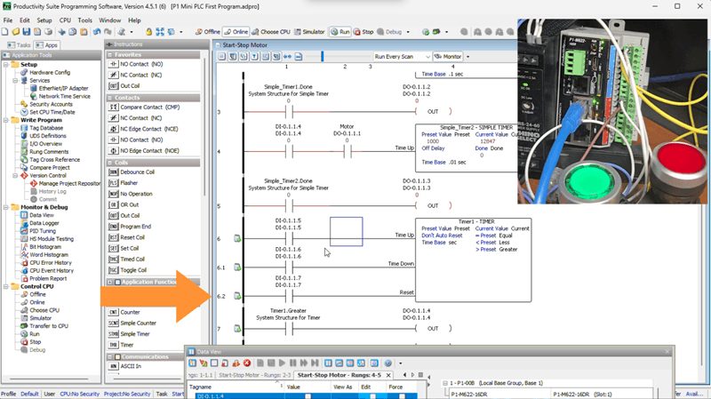
Using the comparison outputs:
The three Boolean output bits — Less, Equal, and Greater — give you three trigger points from a single timer. For example:
- Use Timer1.Less to keep a green indicator light ON while the timer is still below the preset (process running normally).
- Use Timer1.Equal to trigger a single-scan event when the timer hits exactly 20 seconds.
- Use Timer1.Greater to energize an alarm output if the process has run past the expected time.
Practical example with the start-stop circuit:
Add the TMR to your program with the Motor output (DO-0.1.1.1) as the Time Up rung condition. The timer will now track exactly how long the motor has been running. Wire Timer1.Greater to an Out coil on DO-0.1.1.4 — an alarm light that turns ON if the motor has been running for more than 20 seconds without an operator reset. Wire DI-0.1.1.7 (a reset pushbutton) to clear the accumulated time when the operator acknowledges the alarm.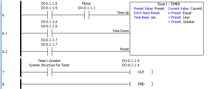
This gives you a basic runtime-exceeded alarm — a practical pattern used in many real industrial applications.
Retentive vs. Non-Retentive Timer Values – P1 Timer
One important decision when configuring any timer in the Productivity Suite is whether to make the Preset and Current values memory-retentive. A retentive tag retains its value through a power cycle — the value is stored in battery-backed memory and restored on power-up. A non-retentive tag resets to its initial value on every power cycle.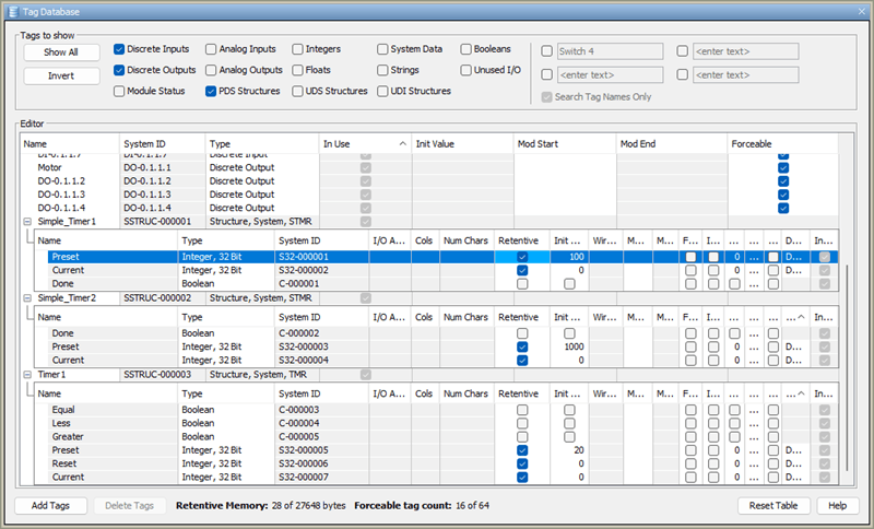
For the Preset, retentive is almost always the right choice. You don’t want your 10-second delay to become 0 seconds after a power interruption.
For the Current value, retentive is useful when you need to track accumulated time across power cycles — for example, a maintenance interval timer that should not reset just because the panel lost power briefly. Non-retentive is appropriate when the timer should always start fresh on power-up, for example, during a startup delay.
The P1-M622-16DR has onboard battery-backed memory to support retentive tags. This is covered in detail in the user manual (Chapter 1 – Getting Started).
Summary – Choosing the Right Timer – P1 Timer
| Requirement | Instruction to Use |
|---|---|
| Output ON after input has been ON for a set time | STMR – On Delay |
| Output stays ON for a set time after input turns OFF | STMR – Off Delay |
| Track elapsed time up and down with comparison outputs | TMR |
| Output ON/OFF at a fixed cycle rate while the input is ON | FLS (Flasher Coil) |
| Output ON for a fixed duration after a momentary trigger | TMC (Timed Coil) |
The FLS and TMC were covered in the Contact and Coil Instructions post. The STMR and TMR are the dedicated timer instructions for more precise time-based control.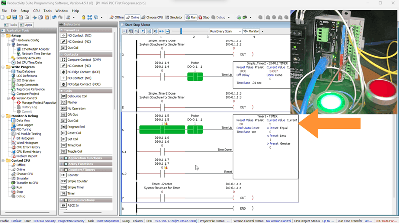
Watch the video below to see the timer instructions used in the Productivity Mini PLC P1-M622-16DR.
Productivity Mini PLC P1-M622-16DR from AutomationDirect
Overview Link (Additional Information on the Unit)
Configuration (Configure and purchase a system – BOM)
User Manual and Inserts (Installation and Setup Guides)
Productivity Suite Programming Software (Free Download Link)
This software contains all of the instruction sets and help files for the Productivity Series.
Next time, we will review the counter instructions for the Productivity Mini PLC P1-M622-16DR.
Watch on YouTube: P1-M622-16DR Mini PLC – Timer Instructions
If you have any questions or need further information, please contact me. Thank you, Garry
Related Posts:
- Master PLC Timers: Simple & Advanced Instructions Revealed
- The Secret of Using Timers
- P1-M622-16DR Mini PLC Contact and Coil Instructions
Many PLC manufacturers offer a range of hardware and software. All programmable logic controllers share similar basic features. Click here to see how I would approach learning about basic PLCs.
Once you are familiar with the basics of the PLC, you will learn the specifics of the controller you will be programming. This is the easiest way to learn about PLC programming.
Click here to see how you can program for free with the ACC PLC Simulator, with 3D scenes you can program.
Here are the controllers that we have covered or are covering at ACC Automation:
LS Electric XGB PLC Series
BRX Do-More Series (Do-More Designer Software + Simulator)
Productivity Series P1000 / P2000
Click PLC Series
Omron CP1H Series
Horner XL4 PLC Series
Arduino Opta PLC
Examples of PLC program development using the five steps.
Click PLC – Easy Transfer Line Programming – Video
Productivity PLC Simulator – Chain Conveyor MS – Video
Five Steps to PLC Program Development – Die Stamping
PLC Programming Example – Process Mixer
PLC Programming Example – Shift Register (Conveyor Reject)
PLC Programming Example – Paint Spraying
PLC Programming Example – Delay Starting of 7 Motors
PLC Programming Example – Pick and Place
PLC Programming Example – Sorting Station (Shift Register)
PLC Programming Example – Palletizer
If you’re like most of my readers, you’re committed to learning about technology. The numbering systems used in PLCs are not difficult to understand. We will walk through the numbering systems used in PLCs. This includes Bits, Decimals, Hexadecimal, ASCII, and Floating Points.
To get this free article, subscribe to my free email newsletter.
Use the information to educate others on how numbering systems work. Sign up now.

The ‘Robust Data Logging for Free’ eBook is also available as a free download. The link is included when you subscribe to ACC Automation.