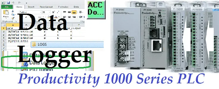
The productivity series of PLCs has a built in data logger. This easy data logger will log up to 64 tag values on a USB (Micro SD) storage device connected to the CPU. The logs will be stored in CSV (Comma Separated Values) file format. Logging can be triggered by the rising edge transition of a Boolean tag (event) or configured to occur at regular intervals (scheduled).
A USB storage device should be normally connected if logging data. The CPU maintains an internal 73KB buffer for temporarily logging data while no USB storage device is present. Data in the buffer will not be retained through a power cycle. Let’s get started.
Previously in this Productivity 1000 series PLC we have discussed:
System Hardware – Video
Installing the Software – Video
Establishing Communication – Video
First Program – Video
Documenting the Program – Video
Monitoring and Testing the Program – Video
Online Editing and Debug Mode – Video
Numbering Systems and Tag Database – Video
Contact and Coil Instructions – Video
Timer Instructions – Video
Counter Instructions – Video
Math Instructions – Video
Data Handling Instructions Part 1 – Video
Data Handling Instructions Part 2 – Video
Array Functions Part 1 – Video
Array Functions Part 2 – Video
Array Functions Part 3 – Video
Program Control – Video
Drum Sequencer Instructions – Video
Data Logger – Productivity 1000
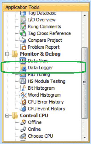
The data logger can be accessed three different ways. Under the Monitor and Debug in the Applications Tools panel, you will see the Data Logger. (See picture above.)
From the Main Menu you can select Setup | Data Logger. The final method is also under the main menu, Tools | Data Logger.
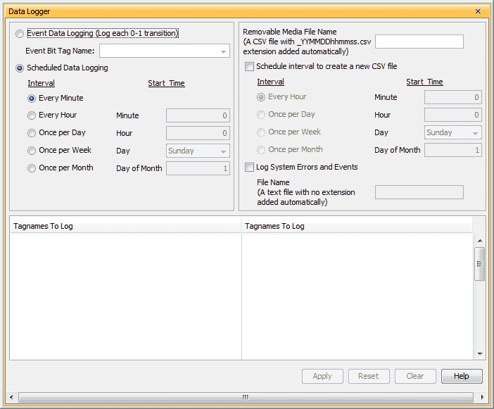
Event Data Logging – The logging will happen on the transition based on the ON status of the specific Boolean Tag (bit) specified in the Event Bit Tag Name.
Scheduled Data Logging – Select Scheduled Data Logging to log data based on a time interval. Select from the following:
Every Minute: Tag Data will be logged once per minute.
Every Hour: Tag Data will be logged once per hour at the designated minute (0 – 59).
Once per Day: Tag Data will be logged once per day at the designated hour (0 – 23) and minute (0 – 59).
Once per Month: Tag Data will be logged once per month at the designated day (1 – 31), hour (0 – 23) and minute (0 – 59).
Removable Media File Name – Enter the prefix of the file name for the USB device. The name entered will always be appended by “-MMDDhhmm.csv” where the time and date are the CPU time and date of the first entry. The CPU will create a “LOGS” folder on the USB storage device and save the log file there.
Schedule interval to create a new CSV file – The name will be the same, but with a new date and time stamp. To prevent loss of buffered data, there must be a USB storage device installed during a scheduled CSV file name change. Select from the following:
Every Hour: A new CSV file will be created once per hour at the designated minute (0 – 59).
Once per Day: A new CSV file will be created once per day at the designated hour (0 – 23) and minute (0 – 59).
Once per Week: A new CSV file will be created once per week at the designated Day (Day of the week (Sunday … Saturday).
Once per Month: A new CSV file will be created once per month at the designated day (1 – 31), hour (0 – 23) and minute (0 – 59).
Log System Errors, Events & File Name – Select to log system errors, events and enter a file name for logging the systems errors and events. This function will create a text file containing system errors and events with the time and date the error or event occurred.
Tagnames To Log – Enter up to 64 Tag Names (32 per column) to be monitored. Each entry in the log file will include time and date fields.
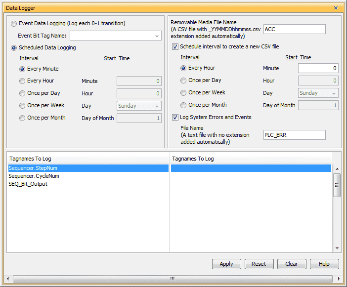
Our example will log the values every minute. (Scheduled logging) The file media name will be ACC. The _YYMMDDhhmmss.csv will be added to the file name. This represents the Year (YY), Month (MM), Day(DD), Hour (hh), Minute (mm) and Second (ss).
Every hour we will start a new CSV file. Log systems errors and events to a file called PLC_ERR.
Our tag names will be from our sequencer example discussed previously.
Hit Apply. We will then use the upper X in the corner to close the Data Logger window.
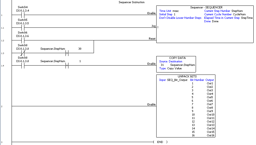
Here is the program that we created for the sequencer. Note: All of the logging is done without a lot of programming.
After running the program, we can then turn the PLC to stop mode and remove the micro SD card from the CPU unit. Looking at the files on the card we will see the LOGS folder.

Inside the LOGS folder we will see the logged information and error and event file.

Opening the log file in excel we can see the three individual tags with the date and time stamp.
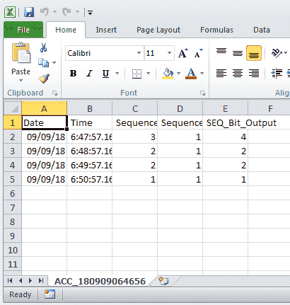
Each of the records are separated by one minute as we specified earlier.
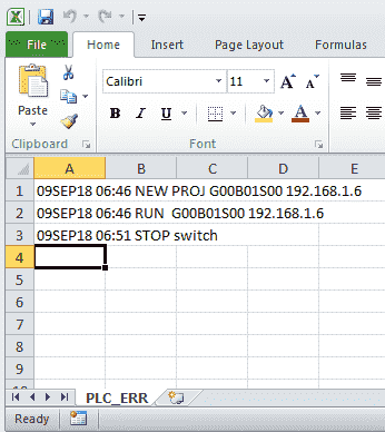
The error and event file will show when the new program was put into the PLC, the RUN and STOP events.
Portable Memory Device System Bits

There are two system bits for the portable memory device (PMD). The portable memory device ready is used to determine the status of the memory device.
The portable memory device eject is used to reject the memory device from the PLC without causing errors on the device.
Data Logging on the Productivity Series PLCs is very easily accomplished with this built in feature.
Download the PLC program here.
Watch the video below to see the data logger that we created in action running on our Productivity 1000 Series PLC.
Productivity 1000 Series PLC from Automation Direct
Overview Link (Additional Information on the Unit)
Configuration (Configure and purchase a system – BOM)
User Manual and Inserts (Installation and Setup Guides)
Productivity Suite Programming Software (Free Download Link)
This software contains all of the instruction sets and help files for the Productivity Series.
Next time we will look at the Web Server in the Productivity 1000 Series PLC.
Watch on YouTube: Productivity 1000 Series PLC Data Logger
If you have any questions or need further information please contact me.
Thank you,
Garry
If you’re like most of my readers, you’re committed to learning about technology. Numbering systems used in PLC’s are not difficult to learn and understand. We will walk through the numbering systems used in PLCs. This includes Bits, Decimal, Hexadecimal, ASCII and Floating Point.
To get this free article, subscribe to my free email newsletter.
Use the information to inform other people how numbering systems work. Sign up now.
The ‘Robust Data Logging for Free’ eBook is also available as a free download. The link is included when you subscribe to ACC Automation.

